
Download

Maxim > Design Support > Technical Documents > Application Notes > Digital Potentiometers > APP 3081
Maxim > Design Support > Technical Documents > Application Notes > Miscellaneous Circuits > APP 3081
Maxim > Design Support > Technical Documents > Application Notes > Video Circuits > APP 3081
Keywords: digital potentiometers, digipots, high frequency digital pot, high bandwidth digital pot, video
pot, video digital pot, potentiometer
APPLICATION NOTE 3081
How to Increase the Bandwidth of Digital
Potentiometers 10x to 100x
Mar 29, 2004
Abstract: A simple circuit technique is described to increase the bandwidth of digital potentiometers by a
factor of 10 to 100. Using this technique can enable digital potentiometers to be used in high frequency
applications at video bandwidths.
Digital potentiometers (or digital pots, or digipots) are extremely useful for controlling or adjusting circuit
parameters. Normally they are only used in DC or low frequency applications due to the inherent
bandwidth limitations of the digital pots. Typical -3dB bandwidths are from 100kHz to several MHz,
depending on the part. However, by using the simple technique described below, you can increase the
signal bandwidths of a potentiometer circuit by 10 to 100 times. You can achieve 0.1dB bandwidths of
4MHz and -3dB bandwidths of over 25MHz. Using this technique, digital pots become a viable option for
video or other high-speed applications.
Limited Adjustment Range
The technique takes advantage of the fact that in many digital potentiometer applications, the pot is used
to fine tune the signal and does not need the full adjustment range of 0% to 100%. Examples are a one-
time factory calibration. In these instances, the digital pots usually provide an overall adjustment range of
10% or less. It is this limited adjustment range which is the key to the bandwidth improvements.
Typical Applications Circuit
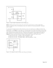
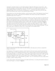
A typical potentiometer circuit configuration is shown in Figure 1. Here, a digital pot is used to vary the
attenuation of a signal. The Digital Pot is R2 and its parasitic capacitance (Cwiper) is also shown. This
capacitance is inherent to all digital pots, and is what limits the circuit bandwidth. R1 and R3 are used to
limit the signal attenuation caused by the digital pot, as the pot code swings from 0 code to full-scale
code.
Page 1 of 10
Directory
- ・ Typical Application Circuit Diagram on P1 P4
- ・ Application Area on P1 P4