EKS 110 - Jungheinrich
EKS 110 - Jungheinrich
EKS 110 - Jungheinrich

Create successful ePaper yourself
Turn your PDF publications into a flip-book with our unique Google optimized e-Paper software.
<strong>EKS</strong> <strong>110</strong>08.09 -BetriebsanleitungG5116190608.09
Declaration of Conformity<strong>Jungheinrich</strong> AG, Am Stadtrand 35, D-22047 HamburgManufacturer or his authorized representative in the CommunityType Option Serial No. Year of construction<strong>EKS</strong> <strong>110</strong>Additional informationAuthorised signatoryDateG EU Declaration of ConformityThe signatories hereby certify that the specified powered industrial truck conforms tothe EU Directive 2006/42/EC (Machine Directive) and 2004/108/EEC (Electro-MagneticCompatibility, EMC) including their amendments as translated into national legislationof the member countries. The signatories are individually empowered in eachcase to compile the technical documentation.08.09 EN1
208.09 EN
ForewordNotes on the operating instructionsThe present ORIGINAL OPERATING INSTRUCTIONS are designed to provide sufficientinstruction for the safe operation of the industrial truck. The information is providedclearly and concisely. The chapters are arranged by letter and the pages arenumbered continuously.The operator manual details different industrial truck models. When operating andservicing the industrial truck, make sure that the particular section applies to yourtruck model.Our trucks are subject to ongoing development. <strong>Jungheinrich</strong> reserves the right to alterthe design, equipment and technical features of the system. No guarantee of particularfeatures of the truck should therefore be assumed from the present operatinginstructions.Safety notices and text mark-upsSafety instructions and important explanations are indicated by the following graphics:DANGER!Indicates an extremely hazardous situation. Failure to comply with this instruction willresult in severe irreparable injury and even death.WARNING!Indicates an extremely hazardous situation. Failure to comply with this instructionmay result in severe irreparable injury and even death.CAUTION!Indicates a hazardous situation. Failure to comply with this instruction may result inslight to medium injury.ZNOTEIndicates a material hazard. Failure to comply with this instruction may result in materialdamage.Used before notices and explanations.08.09 ENt Indicates standard equipmento Indicates optional equipmentCopyrightCopyright of these operating instructions remains with JUNGHEINRICH AG.3
<strong>Jungheinrich</strong> AktiengesellschaftAm Stadtrand 3522047 Hamburg - GermanyTel: +49 (0) 40/6948-0www.jungheinrich.com08.09 EN4
Table of ContentsA Correct Use and Application ................................................... 91 General.................................................................................................... 92 Correct application................................................................................... 93 Approved application conditions.............................................................. 94 Proprietor responsibilities ........................................................................ 105 Adding attachments and/or accessories.................................................. 10B Transport and Commissioning ................................................ 111 Lifting by crane ........................................................................................ 112 Securing the truck during transport ......................................................... 133 Using the Truck for the First Time ........................................................... 144 Operating the truck without its own drive system .................................... 15C Truck Description .................................................................... 171 Application ............................................................................................... 172 Travel direction definition......................................................................... 183 Assemblies and Functional Description................................................... 193.1 Assembly Overview ................................................................................. 193.2 Functional Description ............................................................................. 214 Technical Specifications .......................................................................... 224.1 Performance data .................................................................................... 224.2 Weights.................................................................................................... 234.3 Tyre type.................................................................................................. 234.4 Dimensions.............................................................................................. 244.5 EN norms................................................................................................. 264.6 Conditions of use..................................................................................... 265 Identification points and data plates ........................................................ 275.1 Data plate ................................................................................................ 285.2 Truck capacity plate................................................................................. 29D Battery - Servicing, Recharging, Replacement ....................... 311 Safety Regulations Governing the Handling of Lead-Acid Batteries ....... 311.1 General notes on handling batteries........................................................ 322 Battery types............................................................................................ 323 Exposing the battery................................................................................ 344 Battery removal and installation .............................................................. 355 Charging the battery ................................................................................ 3708.09 EN5
E Operation ................................................................................ 391 Safety Regulations for the Operation of the Forklift Truck....................... 392 Displays and Controls.............................................................................. 412.1 Operator platform position in drive direction............................................ 412.2 Second control station (o) in load direction ............................................. 432.3 Auxiliary lift controls................................................................................. 452.4 Pedestrian <strong>EKS</strong> <strong>110</strong> with gates ............................................................... 462.5 Deadman button and gate ....................................................................... 472.6 Displays ................................................................................................... 483 Starting up the truck ................................................................................ 503.1 Checks and operations to be performed before starting daily operation . 503.3 Setting up the operator position............................................................... 514 Industrial Truck Operation ....................................................................... 524.1 Safety regulations for truck operation...................................................... 524.2 Preparing the truck for operation ............................................................. 544.3 Parking the truck securely ....................................................................... 554.4 Emergency Disconnect............................................................................ 554.5 Deadman button ...................................................................................... 564.6 Travel....................................................................................................... 574.7 Steering ................................................................................................... 584.8 Brakes ..................................................................................................... 584.9 Travelling in pedestrian touch mode (o) .................................................. 594.10 Operator platform lifting and lowering...................................................... 604.11 Auxiliary Lift – raising and lowering ......................................................... 624.12 Lifting and lowering in pedestrian touch mode ........................................ 644.13 Lifting and lowering the operator platform with lift cutout (o) ................... 684.14 Lifting, transporting and depositing loads ................................................ 694.15 Adjusting the forks ................................................................................... 704.16 Walk-on load section with pallet guard ( (Zusatzausstattung))................ 714.17 Negotiating narrow aisles ........................................................................ 734.18 Trucks with rail guidance and aisle recognition (Zusatzausstattung) ...... 754.19 Emergency lowering ................................................................................ 785 CANCODE keypad (o)............................................................................. 805.1 Keypad .................................................................................................... 805.2 Parameters .............................................................................................. 815.3 Parameter Settings.................................................................................. 816 Troubleshooting....................................................................................... 856.1 Truck does not start................................................................................. 85F Industrial Truck Maintenance .................................................. 871 Operational Safety and Environmental Protection................................... 872 Maintenance Safety Regulations............................................................. 873 Servicing and Inspection ......................................................................... 914 Maintenance checklist ............................................................................. 925 Lubricants and Lubrication Schedule ...................................................... 935.1 Handling consumables safely.................................................................. 935.2 Lubrication Schedule ............................................................................... 955.3 Consumables........................................................................................... 9608.09 EN6
6 Maintenance and repairs ......................................................................... 976.1 Preparing the truck for maintenance and repairs .................................... 976.2 Tightening the wheel nuts........................................................................ 986.3 Mast retainer assembly and removal....................................................... 996.4 Front panel assembly and disassembly .................................................. 1026.5 Electrical System ..................................................................................... 1036.6 Checking electrical fuses......................................................................... 1047 Restoring the truck to service after maintenance and repairs ................. 1058 Decommissioning the industrial truck ...................................................... 1068.1 Prior to decommissioning ........................................................................ 1068.2 During decommissioning ......................................................................... 1068.3 Restoring the truck to service after decommissioning ............................. 1079 Safety tests to be performed at intervals and after unusual incidents ..... 10810 Final de-commissioning, disposal............................................................ 10811 Human vibration measurement ............................................................... 10808.09 EN7
808.09 EN
AppendixJH Traction Battery Operating InstructionsZThese operating instructions apply only to <strong>Jungheinrich</strong> battery models. If usinganother brand, refer to the manufacturer's operating instructions.0506.GB1
20506.GB
ACorrect Use and Application1 GeneralThe industrial truck described in the present operating instructions is designed for lifting,lowering and transporting load units.It must be used, operated and serviced in accordance with the present instructions.Any other type of use is beyond the scope of application and can result in damage topersonnel, the industrial truck or property.2 Correct applicationNOTEThe maximum load and load distance are indicated on the load chart and must not beexceeded.The load must rest on the load handler or be lifted by an attachment approved by themanufacturer.The load must rest on the back of the fork carriage and centrally between the forks.– Lifting and lowering of loads.– Transporting lowered loads.– Do not travel with a raised load (>30 cm).– Do not carry or lift passengers.– Do push or pull load units.3 Approved application conditionsDANGER!Do not exceed the permissible surface and spot load limits on the travel routes.At blind spots get a second person to assist.The driver must ensure that the loading ramp / bridge cannot move or come looseduring loading / unloading.– Operation in industrial and commercial environments.– Permissible temperature range 5°C to 40°C.– Application only on level surfaces to DIN 15185.– Safety clearances between the truck and rack to EN 1726-2 item 7.3.2.– Minimum 100 mm safety clearance between rail guided truck and rack.– Minimum 125 mm safety clearance between wire guided truck and rack.08.09 EN9
4 Proprietor responsibilitiesFor the purposes of the present operating instructions the “proprietor” is defined asany natural or legal person who either uses the industrial truck himself, or on whosebehalf it is used. In special cases (e.g. leasing or renting) the proprietor is consideredthe person who, in accordance with existing contractual agreements between theowner and user of the industrial truck, is charged with operational duties.The proprietor must ensure that the industrial truck is used only for the purpose forwhich it is intended and that there is no danger to life and limb of the user and thirdparties. Furthermore, accident prevention regulations, safety regulations and operating,servicing and repair guidelines must be followed. The proprietor must ensure thatall users have read and understood these operating instructions.NOTEFailure to comply with the operating instructions shall invalidate the warranty. Thesame applies if improper work is carried out on the truck by the customer or third partieswithout the permission of the manufacturer.5 Adding attachments and/or accessoriesAdding accessoriesThe mounting or installation of additional equipment which affects or enhances theperformance of the forklift truck requires the written permission of the manufacturer.Local authority approval may also need to be obtained.Local authority approval does not however constitute the manufacturer’s approval.08.09 EN10
BTransport and Commissioning1 Lifting by craneWARNING!Improper lifting by crane can result in accidentsThe use of unsuitable lifting gear can cause the truck to crash when being lifted bycrane.Prevent the truck and mast from striking other objects when they are being raised,and avoid any uncontrolled movement. If necessary, secure the truck and mast withguide ropes.The truck and mast should only be laden by people who are trained in handling liftingslings and tools.Wear safety shoes when lifting by crane.Do not stand under a swaying load.Do not walk into or stand in a hazardous area.Only use lifting gear with sufficient capacity (for truck weight see truck data plate).Attach the crane slings only to the prescribed strap points and prevent them fromslipping.Use the lifting gear only in the prescribed load direction.Crane slings should be fastened in such a way that they do not come into contactwith any truck attachments when it is being raised.Lifting the truck by craneRequirements– Load handler lowered– Key switch set to OFF– Key removed, for code lock the O keypressed.– Emergency Disconnect OFFTools and Material Required– Lifting gear– Crane slingsProcedure• Secure the crane slings to the attachmentpoints (1) and (2).The truck can now be lifted by crane.4108.09 EN11
1208.09 EN
2 Securing the truck during transportWARNING!Accidental movement during transportImproper fastening of the truck and mast during transport can result in serious accidents.Loading must be carried out by specially trained staff in accordance with recommendationscontained in Guidelines VDI 2700 and VDI 2703 In each case correctmeasurements must be made and appropriate safety measures adopted.The truck must be securely fastened when transported on a lorry or a trailer.The lorry / trailer must have fastening rings.Use wedges to prevent the truck from moving.Use only tension belts or tie-down straps or with sufficient strength.Securing the truck for transportRequirements– Load handler lowered– Key switch set to OFF– Key removed, for code lock the O keypressed– Emergency Disconnect pressed– Battery disconnected42Tools and Material Required– Tension belts/tie down strapsProcedure• Position the truck securely on a lorry or trailer.• Attach at least four tension belts (42) to the mast, 2 on the left and 2 on the right.The truck can now be transported.08.09 EN13
3 Using the Truck for the First TimeZPreparing the truck for commissioningProcedure• Check the equipment is complete.• If necessary install the battery, (see "Battery removal and installation" on page 35)The truck should only be operated with battery current. Rectified AC current willdamage the electronic components. The battery leads (tow cable) must be lessthan 6m long.• Charge the battery, (see "Charging the battery" on page 37).The truck can now be started, (see "Starting up the truck" on page 50).08.09 EN14
4 Operating the truck without its own drive systemReleasing the brakeCAUTION!43 16Uncontrolled truck movementDo not release the brake on slopes or inclines.Apply the brake again when you reachyour destination.Do not park the truck with the brake released.Tools and Material Required– Two M5x42 hex. socket screws– Allen keyProcedure• Turn the main switch/isolator “OFF”.• Set the key switch OFF and remove the key.• Prevent the truck from rolling away.• Lift up the front panel (16) and put it to one side, (see "Front panel assembly anddisassembly" on page 102).• Insert two M5x42 hex. socket screws screws (43) as far as the stop and lift up theanchor plate.The brake is now released and the truck can be moved.Applying the brakeProcedure• Unscrew the two M5x42 hex. socket screws (43) again.• Refit and close the front panel (16).Braking is now restored again.08.09 EN15
1608.09 EN
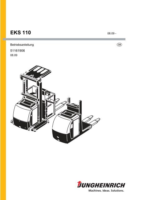
CTruck Description1 ApplicationThe <strong>EKS</strong> <strong>110</strong> is an electric powered vertical order picker. The truck is designed totransport and pick goods on level surfaces in accordance with DIN 15185.It is designed to lift open bottom, cross-board pallets and roll cages. The truck is notsuitable for stacking pallets in racking systems. The driver's cab rises with the loadhandler so that the shelf heights to be operated are visible and within easy reach.The racking systems must be set up for the <strong>EKS</strong> <strong>110</strong>. The safety clearances stipulatedby the manufacturer (e.g. EN 1726-2 item 7.3.2) must be observed.There must be a minimum safety clearance between the rack and the truck of– 100 mm for rail guided trucks and– 125 mm for wire-guided trucks.The ground surface must comply with DIN 15185. Guide rails must be provided in thenarrow aisles for the rail guidance system. Vulkollan guide wheels attached to thetruck chassis guide the truck between the guide rails.The truck is fitted as standard with a simplex mast (E mast) or a duplex mast (ZZmast) (lift heights (see "Technical Specifications" on page 22)). Auxiliary lift is optionallyavailable, which allows the forks to be raised a further 800 mm.08.09 EN17
2 Travel direction definitionThe following determinations have been made for travel direction specification:12 34Item Travel direction1 Left3 Load direction4 Right2 Drive direction08.09 EN18
3 Assemblies and Functional Description3.1 Assembly Overview5 6 7 8 9 10 1112 13 141516 1708.09 EN19
Item Description5 t Overhead guard6 o Duplex mast7 t Controller8 t Gate (from 1200 mm)9 t Simplex mast11 t Fork10 t Operator platform17 t Electrical system cover16 t Drive panel15 o Guide wheels14 t Driver's display13 t Battery cover12 t Drive wheelt Standard equipmento Optional equipment08.09 EN20
3.2 Functional DescriptionSafety MechanismsThe truck has an enclosed geometry. The drive wheel is surrounded by a solid skirt.The operator platform is cushioned against impacts. The overhead guard protects thedriver from any falling objects. Gates on either side of the operator platform cut out alltravel and lifting operations beyond a lift height of 1200 mm. In the optional "rail guidancewith aisle recognition” mode (o) in narrow aisles, the two-hand operation button(o) must also be pressed to enable travel and lifting. The two-hand operation systemprevents the operator from reaching into the rack while the truck is travelling or lifting.Emergency Disconnect: The Emergency Disconnects switches off all electricalfunctions when applied.Truck designThe truck is a threewheel design with a steered drive wheel within the enclosed truckgeometry. An easily accessible front panel, a detachable battery cover and a detachableelectrical system cover provide easy access to all the components.BrakesBraking is performed by changing travel direction with the controller (inversion braking),or by releasing the controller (coasting brake). When the electrical system is disconnectedthe spring-loaded brake acts as a parking brake.Steering systemThe steer range is 90° in either direction. The steering wheel acts electrically on thesteering transmission motor. The spur gear transfers the steering movement to thedrive wheel. In "rail guidance with aisle recognition" mode (o) the steering is automaticallykept in the straight-ahead position.Hydraulic systemWhen lifting is activated, the pump unit starts to operate, supplying hydraulic oil fromthe oil reservoir to the lift cylinder. A hydraulic accumulator and a flow control valveensure cushioned lifting and lowering.Lift mechanismThe truck has a welded simplex mast. The load carriage with the operator platformand forks runs on flanged rollers to limit frictional loss and ensure low energy consumption.Lifting is performed through the hydraulic cylinder extension. In auxiliary liftmode (o) the forks are raised by a centre-mounted lift cylinder via a pulley chain. Thetruck can be fitted with a duplex mast.08.09 ENControls and displaysControls and displays are clearly arranged in the driver’s cab. A controller governsthe travel speed. Lifting, lowering and the horn function are operated by buttons withineasy reach. If the truck is fitted with auxiliary lift (o) “Z” the controls for lifting/loweringthe auxiliary lift are also arranged in the same way on the load side (on the auxiliarylift). The driver's display shows the battery charge, the service hours plus service anddiagnostic data. A wheelbase display indicates the current steer angle of the drivewheel.21
4 Technical SpecificationsZ Technical data specified in accordance with VDI 2198.Technical modifications and additions reserved.Z All data applies to the L and Z versions unless otherwise indicated.4.1 Performance dataDescription<strong>EKS</strong> <strong>110</strong>(100 E)<strong>EKS</strong> <strong>110</strong>(160 E)<strong>EKS</strong> <strong>110</strong>(190 E)<strong>EKS</strong> <strong>110</strong>(280 ZZ)Q Rated capacity 1000 1000 kgTravel speed w / w.o. ratedload9,8/10,1 9,0/9,0 9,0/9,0 km/hLift speed with / without ratedload, Z0,16/0,20 0,13/0,17 0,21/0,30 m/sLift speed with / without ratedload, L0,16/0,20 0,13/0,17 0,21/0,30 m/sLower speed with / withoutrated load, Z0,21/0,19 0,30/0,28 m/sLower speed with / withoutrated load, L0,21/0,19 0,30/0,28 m/sGradeability with / withoutrated load5/10 %Traction motor, output (S2 =60 min)2,8 kWLift motor, output at S3 15% 3 kWLift motor, output at S3 5 % 2,2 kWLift motor, output at S3 20 % 6 kW08.09 EN22
4.2 WeightsDescriptionTruck weight including batteryL/ZAxle load with load front/rear(with battery) ZAxle load without load front/rear (with battery) ZAxle load with load front/rear(with battery) LAxle load without load front/rear (with battery) L<strong>EKS</strong> <strong>110</strong>(100 E)1756/1859481/23771083/775476/22801078/678<strong>EKS</strong> <strong>110</strong>(160 E)1934/2036461/2575<strong>110</strong>5/931456/2478<strong>110</strong>0/834<strong>EKS</strong> <strong>110</strong>(190 E)1970/2072461/26111113/959456/2514<strong>110</strong>8/862<strong>EKS</strong> <strong>110</strong>(280 ZZ)2270/2390755/26351330/1060765/25051305/965kgkgkgkgkg4.3 Tyre typeDescriptionRatingTyre typeVulkolland1 Tyre size, front 230x80 mmd2 Tyre size, rear 150x30 mm08.09 EN23
4.4 Dimensionsh4Ch1990217 yh7slQh9h13 h3h12h6l2l1Wab1b5b11ea/2a/2AstDescription<strong>EKS</strong> <strong>110</strong>(100 E)<strong>EKS</strong> <strong>110</strong>160 E)<strong>EKS</strong> <strong>110</strong>(190 E)<strong>EKS</strong> <strong>110</strong>(280 ZZ)c Load centre 600 600 mm08.09 EN24
Description<strong>EKS</strong> <strong>110</strong>(100 E)<strong>EKS</strong> <strong>110</strong>160 E)x Load distance 178 185 mmy Wheelbase 1300 1385 mmh 1 Mast height retracted 1660 1 2260 2560 2251 mmh 3 Lift 1000 1600 1900 2800 mmh 4Mast height (extended)(h 1 +h 3 )2660 1 3830 4130 5034 mmh6 Overhead guard height 2230 2230 mmh 7 Seat height / standing height 200 200 mmh 9 Aux. lift Z 800 800 mmh 12 Truck height raised (h 3 +h 7 ) 1200 1800 2100 3000 mmh 13 Lowered height 80 80 mmAstAisle width for pallets 2 800 x1200 longit.3153 3245 mmAstAisle width for pallets 21000 x 1200 transverse3040 3131 mmb 1 /b 2Overall width 810 900 mmb 4 Inside straddle 430 520 mmb 5 Outside straddle 540 540 mmb 11 Track width, rear 630 720 mmI 1 Overall length L/Z 2895 2985 mmI 2 Headlength L/Z 1695 1785 mmI 3 Platform length L/Z 775/710 775/710 mmI Fork length 800 mmWa Turning radius 1518 1603 mms/e/lFork dimensions L 60 / 160 / 1200s/e/lFork dimensions Z 65 / 160 / 1200m 1Ground clearance with loadbelow mast<strong>EKS</strong> <strong>110</strong>(190 E)<strong>EKS</strong> <strong>110</strong>(280 ZZ)60 / 160 /120065 / 160 /12001 equipped with overhead guard (o) +570 mm2 For rotating in front of the occupied pallet space in accordance with VDI 2198 (diagonalmethod)mmmm35 35 mma Safety clearance 200 200 mmFork carriage ISO 2328,class/type A,BFEM 2A (optional)08.09 EN25
4.5 EN normsZZZNoise emission level– <strong>EKS</strong> <strong>110</strong>: 68 dB(A)in accordance with EN 12053 as harmonised with ISO 4871.The noise emission level is calculated in accordance with standard procedures andtakes into account the noise level when travelling, lifting and when idle. The noiselevel is measured at the level of the driver's ear.Vibration– <strong>EKS</strong> <strong>110</strong>: 0,96 m/s²in accordance with EN 13059The vibration acceleration acting on the body in the operating position is, in accordancewith standard procedures, the linearly integrated, weighted acceleration inthe vertical direction. It is calculated when travelling over bumps at constant speed.These recordings were taken on a single occasion and must not be confused withthe human vibrations of the "2002/44/EC/Vibrations" operator directive. The manufactureroffers a special service to measure these human vibrations, (see "Humanvibration measurement" on page 108).Electromagnetic compatibility (EMC)The manufacturer confirms that the truck adheres to the limits for electromagneticemissions and resistance as well as the static electricity discharge test in accordancewith EN 12895 as well as the standardised instructions contained therein.No changes to electric or electronic components or their arrangement may bemade without the written agreement of the manufacturer.WARNING!Medical equipment can be damaged by non-ionised radiationElectrical equipment on the truck emitting non-ionised radiation (e.g. wireless datatransmission) can affect operators' medical equipment (pacemakers, hearing aidsetc.) and result in malfunctions. Consult with a doctor or the medical equipment manufacturerto clarify whether it can be used near the industrial truck.4.6 Conditions of useZAmbient temperature– operating at 5°C to 40°CSpecial equipment and authorisation are required if the truck is to be constantlyused in conditions of extreme temperature or air humidity fluctuations.08.09 EN26
9871115 Identification points and data platesWarnings and notices such as load charts, strap points and data plates must be legibleat all times. Replace if necessary.18 19 20 2122610520004123223241925262526212808.09 ENItem Description18 “Danger of trapping” warning19 "Do not reach through the mast" warning20 “Do not step under the load handler” warning21 “Caution, pushbutton operation” warning22 Test plaque (o)23 Capacity Plate, Capacity / Load Centre of Gravity / Lift Height24 Truck data plate25 Jack contact point26 Strap point for crane lifting22 “Caution: Low voltage electronics” warning28 “Do not carry passengers” warning27
5.1 Data plate29 30 31 32 3334353637383940ZItem Description Item Description29 Type 35 Year of manufacture30 Serial number 36 Load centre (mm)31 Rated capacity (kg) 37 Output32 Battery voltage (V) 38 Min./max. battery weight (kg)33 Net weight w.o. battery (kg) 39 Manufacturer34 Option 40 Manufacturer’s logoFor queries regarding the truck or ordering spare parts always quote the truck serialnumber (30).08.09 EN28
5.2 Truck capacity plateThe capacity plate (23) gives the capacity (Q) of the truck in kg for a vertical mast.The maximum capacity is shown as a table with a given load centre of gravity D (inmm) and the required lift height H (in mm).Example of how to calculate the maximum capacityFor a load centre of gravity D of 600 mm and a max. lift height H of 1000 mm the maximumcapacity Q is 1000 kg.08.09 EN29
3008.09 EN
DBattery - Servicing, Recharging, Replacement1 Safety Regulations Governing the Handling of Lead-AcidBatteriesMaintenance personnelBatteries may only be charged, serviced or replaced by trained personnel. This operatormanual and the manufacturer’s instructions concerning batteries and chargingstations must be observed when carrying out the work.Fire protectionDo not smoke and avoid naked flames when handling batteries. Wherever a truck isparked for charging there must be no flammable material or consumables capable ofcreating sparks within a 2 metre radius of the truck. The room must be ventilated. Fireprotection equipment must be on hand.Battery maintenanceThe battery cell covers must be kept dry and clean. The terminals and cable shoesmust be clean, secure and have a light coating of dielectric grease.CAUTION!Before closing the battery panel make sure that the battery cable cannot be damaged.There is a risk of short circuits with damaged cables.Battery disposalBatteries may only be disposed of in accordance with national environmental protectionregulations or disposal laws. The manufacturer’s disposal instructions must befollowed.08.09 EN31
1.1 General notes on handling batteriesWARNING!Batteries can be hazardousBatteries contain an acid solution which is poisonous and corrosive. Above all avoidany contact with battery acid.Dispose of used battery acid in accordance with regulations.Always wear protective clothing and goggles when working with batteries.Do not let battery acid come into contact with skin, clothing or eyes. If necessary,rinse with plenty of clean water.Call for a doctor immediately in the event of physical damage (e.g. skin or eye contactwith battery acid).Neutralise any spilled battery acid immediately with plenty of water.Only batteries with a sealed battery container may be used.Follow national guidelines and legislation.WARNING!Using unsuitable batteries can cause accidentsThe weight and dimensions of the battery have a considerable effect on the operationalsafety and capacity of the industrial truck. Changing the battery features requiresthe manufacturer’s approval, as compensating weights are required if smallerbatteries are fitted. When replacing/installing the battery make sure the battery is securelylocated in the battery compartment of the truck.Park the truck securely before carrying out any work on the batteries ((see "Parkingthe truck securely" in chapter 4.3)).2 Battery typesDepending on the model, the truck will be supplied with different battery types. Thefollowing table shows which combinations are included as standard:Battery type Capacity Weight24 volt battery (maintenance-free) 4 EPzV 480 Ah 480 kg24 volt battery 4 EPzS 560 Ah24 volt battery 4 EPzS 620 Ah24 volt battery (maintenance-reduced) 4 EPzW 560 AhThe battery weights can be taken from the battery data plate. Batteries with non insulatedterminals must be covered with a non slip insulating mat.NOTEOnly use a battery whose weight is within the minimum and maximum rangestated on the truck’s data plate.08.09 EN32
Failure to comply with the prescribed battery weight range can render the truckunstable.08.09 EN33
3 Exposing the batteryZRequirements– Load handler lowered– Key switch set to OFF– Key removed, for code lock the Okey pressed44– Emergency Disconnect OFFProcedure13• Grab the battery cover (13) byboth handles (44) and lift it up asfar as the stop.The battery cover is held up by itsown weight.• Restore all covers and connectionsto their operating position before starting up the truck.• Close the battery panel using the handles (44) only.08.09 EN34
4 Battery removal and installationWARNING!Accident risk during battery removal and installationDue to the battery weight and acid there is a risk of trapping or scalding when the batteryis removed and installed.Note the "Safety regulations for handling acid batteries" section in this chapter.Wear safety shoes when removing and installing the battery.Use only batteries with insulated cells and terminal connectors.Park the truck on a level surface to prevent the battery from sliding out.Make sure the crane slings have sufficient capacity to replace the battery.Use only approved battery replacement devices (battery roller stand, replacementtrolley etc.).Make sure the battery is securely located in the truck's battery compartment.Removing the batteryRequirements– Park the truck securely, (see "Battery removaland installation" on page 35).– Battery disconnected.Tools and Material Required– Crane or forklift truck– Crane slings– Battery replacement trolley (o)4546Procedure• Pull the clamping lever (6) of the batterylock 180° anti-clockwise.47• Pull the battery lock up.• Removing the battery with a replacementtrolley (o)• Pull the battery sideways off the truck.Follow the operating instructions of the battery replacement trolley manufacturer!• Removing the battery with a crane or forklift truck• Attach the hooks of the crane slings to the strap eyes (5) on the battery.The discharged crane slings must not fall onto the battery cells.• Slowly and carefully lift the battery out of the truck.The battery is now removed.08.09 EN35
Battery installationRequirements– Truck parked.– Battery lock removed.Tools and Material Required– Crane or forklift truck– Crane slings– Battery replacement trolley (o)Procedure• Installing the battery with a crane or forklift truck• Attach the hooks of the crane slings to the strap eyes (45) on the battery.The discharged crane slings must not fall onto the battery cells.• Slowly and carefully lower the battery into the truck.• Installation with a battery replacement trolley• Position the battery replacement trolley and battery in front of the battery compartment.• Push the battery as far as the stop in the battery compartment.• Insert the battery lock.• Pull the clamping lever (47) of the battery lock 180° clockwise.• Attach the battery connector (46) to the truck.• Check all cables and plug connections for visible signs of damage.• Close the battery cover.When the battery has been installed the truck is ready for operation.08.09 EN36
5 Charging the batteryWARNING!The gases produced during charging can cause explosionsThe battery produces a mixture of nitrogen and hydrogen (electrolytic gas) duringcharging. Gassing is a chemical process. This gas mixture is highly explosive andmust not be ignited.Switch the charging station and truck off first before connecting/disconnecting thecharging cable of the battery charging station to/from the battery connector.The charger must be adapted to the battery in terms of voltage and charge capacity.Before charging, check all cables and plug connections for visible signs of damage.Ventilate the room in which the truck is being charged.The battery cover must be open and the battery cell surfaces must be exposed duringcharging to ensure adequate ventilation.Do not smoke and avoid naked flames when handling batteries.Wherever a truck is parked for charging there must be no flammable material orconsumables capable of creating sparks within a 2 metre radius of the truck.Fire protection equipment must be provided.Do not lay any metallic objects on battery.It is essential to follow the safety regulations of the battery and charger station manufacturers.Charging the batteryRequirements– Battery exposed.– Charger switched off.Procedure• Remove the battery connector (3).• Remove any insulating mats from thebattery.• Connect the charging cable (4) of thebattery charger station with the batteryconnector (3).• Switch on the charger. Charge the batteryin accordance with the battery andbattery charger manufacturers’ instructions.The battery is now charged.46 4808.09 EN37
3808.09 EN
EOperation1 Safety Regulations for the Operation of theForklift TruckDriver authorisationThe truck may only be used by suitably trained personnel, who have demonstrated tothe proprietor or his representative that they can drive and handle loads and havebeen authorised to operate the truck by the proprietor or his representative.Driver’s rights, obligations and responsibilitiesThe driver must be informed of his duties and responsibilities and be instructed in theoperation of the truck and shall be familiar with the operating instructions. The drivershall be afforded all due rights. Safety shoes must be worn for pedestrian operatedtrucks.Unauthorised use of truckThe driver is responsible for the truck during the time it is in use. The driver must preventunauthorised persons from driving or operating the truck. Do not carry passengersor lift other people.Damage and faultsThe supervisor must be immediately informed of any damage or faults to the truck orattachment. Trucks which are unsafe for operation (e.g. wheel or brake problems)must not be used until they have been rectified.RepairsThe driver must not carry out any repairs or alterations to the truck without the necessarytraining and authorisation to do so. The driver must never disable or adjustsafety mechanisms or switches.08.09 EN39
Hazardous areaWARNING!Risk of accidents / injury in the hazardous area of the truckThe hazardous area is defined as the area in which a person is at risk due to truckmovement, lifting operations, the load handler (e.g. forks or attachments) or the loaditself. This also includes areas which can be reached by falling loads or lowering operatingequipment.Instruct unauthorised people to leave the hazardous area.Give a warning signal with plenty of time for people to leave.If unauthorised personnel are still within the hazardous area stop the truck immediately.Safety devices and warning labelsIt is essential to observe the safety devices, warning decals ((see "Identificationpoints and data plates" on page 27)) and warning notices in this manual.08.09 EN40
2 Displays and Controls2.1 Operator platform position in drive direction4 5 5 52 53 5 55 56 575814597606162 63646508.09 ENItem Control / Display Function49 Clip board t For holding A4 paper50 Lower button t Lowers the operator platform and forks.51 Lift button t Lifts the operator platform and forks.52 Aux. lift “raise” button o Raises the forkso 2nd control station53 Aux. lift “lower” button o Lowers the forkso 2nd control station54 Warning button t Activates a warning signal.o 2nd control station55 Pedestrian mode lowerbuttonoPedestrian mode optional feature: Lowers theoperator platform and forks.41
Item Control / Display Function56 Pedestrian mode liftbuttono Pedestrian mode optional feature: Lifts theoperator platform and forks.57 Drive direction pedestriantouch modeo Pedestrian mode optional feature, travel iscontinued as operator walks beside in drivedirection (slow travel).58 Fork direction pedestriantouch modeo Pedestrian mode optional feature, travel iscontinued as operator walks beside in forksdirection (slow travel).14 Driver's display t Displays important travel and lift parameters;selection and display of steering modes, warnings,incorrect operation notes and service displays.59 Emergency Disconnect t The circuit is interrupted, all electrical functionsare cut out and the truck automatically brakes.7 Controller t Controls the travel direction and speed.o 2nd control station60 Steering wheel t Steers the truck.61 ButtonTwo-hand operationo Releases lifting and travel when pressed (in railguidance mode with aisle recognition).62 Indicator o End of aisle safety device optional feature:Indicates reduced travel speed63 Reset button o End of aisle safety device optional feature:Releases normal travel speed.64 Key switch and key t Switches control voltage on and off. Removingthe key prevents the truck from being switchedon by unauthorised personnel.CANCODE keypad o Code lock, replaces the key switch. Switchescontrol current on and off. Enables truck functions.Change access codes.ISM access module o Replaces the key switch. Checks the card (orthe transponder). Enables truck functions. Timeoutmonitoring. Lists the truck users (shifts)and saves them onto the card. Operationaldata acquisition.65 Emergency Disconnect o Pedestrian mode optional feature: Disconnectsthe supply current and deactivates all electricalfunctions, causing the truck to brake automatically.t Standard equipmento Optional equipment08.09 EN42
2.2 Second control station (o) in load direction66 67 68 75 5 5 52 535758656970Item Control / Display Function50 Lower button t Lowers the operator platform and forks.08.09 EN51 Lift button t Lifts the operator platform and forks.52 Aux. lift “raise” button o Raises the forks.53 Aux. lift “lower” button o Lowers the forks.54 Warning button t Activates a warning signal.57 Drive direction pedestriantouch mode58 Fork direction pedestriantouch modeooPedestrian mode optional feature, travel iscontinued as operator walks beside in drivedirection (slow travel).Pedestrian mode optional feature, travel iscontinued as operator walks beside in forksdirection (slow travel).7 Controller t Controls the travel direction and speed.60 Steering wheel t Steers the truck.43
Item Control / Display Function65 Emergency Disconnect o Pedestrian mode optional feature: Disconnectsthe supply current and deactivates all electricalfunctions, causing the truck to brake automatically.66 Steering wheel (2ndcontrol station)o Steers the truck.67 Two-hand operationbutton (2nd control station)68 2. Emergency Disconnect2nd control stationooReleases lifting and travel when pressed (in railguidance mode with aisle recognition).Disconnects the supply current and deactivatesall electrical functions, causing the truckto brake automatically.69 Aux. lift “raise” button o Pedestrian mode optional feature: Raises theforks.70 Aux. lift “lower” button o Pedestrian mode optional feature: Lowers theforks.t Standard equipmento Optional equipment08.09 EN44
2.3 Auxiliary lift controls715253Item Control / Display Function52 Aux. lift “raise” button o Raises the forkso 2ndcontrol station53 Aux. lift “lower” button o Lowers the forkso 2nd control position71 Two-hand operation,FEM fork raise/lowerbuttont Standard equipmento Optional equipmentoRaises/lowers the forks (aux. lift) Use in conjunctionwith buttons 4 and 5.08.09 EN45
2.4 Pedestrian <strong>EKS</strong> <strong>110</strong> with gates55865655Item Control / Display Function55 Pedestrian mode lowerbuttono Pedestrian mode optional feature: Lowers theoperator platform and forks.56 Pedestrian mode liftbuttono Pedestrian mode optional feature: Lifts theoperator platform and forks.57 Drive direction pedestriantouch modeo Pedestrian mode optional feature, travel iscontinued as operator walks beside in drivedirection (slow travel).58 Fork direction pedestriantouch modeoPedestrian mode optional feature, travel iscontinued as operator walks beside in forksdirection (slow travel).65 Emergency Disconnect o Pedestrian mode optional feature: Disconnectsthe supply current and deactivates all electricalfunctions, causing the truck to brake automatically.t Standard equipmento Optional equipment08.09 EN46
2.5 Deadman button and gate87273Item Control / Display Function8 Gate o Open: Lifting and travel inhibited from a liftheight of 1200 mm.Closed: Lifting and travel released.72 Deadman button t Released: Travel inhibited, or truck decelerates.Applied: Travel released.73 2nd control stationdeadman buttontoStandard equipmentOptional equipmentoReleased: Travel inhibited, or truck decelerates.Applied: Travel released, operation changed to2nd control station.08.09 EN47
2.6 DisplaysDescriptionThe driver’s display unit represents the operator-truck interface. It is both a displayand control unit for the operator and the service engineer.Adjustments to the truck can be made by pressing the four short stroke keys (89, 90,91, 92). The LEDs of the 4 luminous buttons (75, 76,86, 87) can show 3 conditions:on, flashing or off.The display unit gives information on the travel direction, steering angle, batterycharge condition and other selected truck parameters.75 76 77 78 79 80 81 8283848687858889 909192Item Description75 Slow travel (green icon)76 Service mode is active (yellow spanner icon), Service interval expired (iconflashing)77 Steering angle display in 30° increments in arrow form78 Travel direction display79 No function80 Time display (hours: minutes)81 Battery discharge status82 Discharge indicator83 Set speed (drive direction) for current profile (in bars from 1 to 5)84 No function85 Profile number (travel profile 1, 2 or 3)86 Deadman switch not pressed (yellow icon)08.09 EN48
Item Description87 Overtemperature (red icon)88 Warning and fault indication as text (14 segment display) and data registration89 Slow travel90 No function91 Shift key (for changing display and accessing service mode)92 Profile key to select travel modeDisplay Operation DescriptionLED 81 flashes Battery empty, main lift cutoutLED 86 on Deadman button not pressedINFO 09 LED 75 Slow travel applied or forced by batterylatchingINFO 10 LED 87 on Drive motor overtemperature08.09 EN49
3 Starting up the truck3.1 Checks and operations to be performed before starting daily operationWARNING!Damage and other truck or attachment (special equipment) defects can resultin accidents.If damage or other truck or attachment (special equipment) defects are discoveredduring the following checks, the truck must be taken out of service until it has beenrepaired.Report any defects immediately to your supervisor.Tag out and decommission a faulty lift truck.Only return the truck to service when you have identified and rectified the fault.Visual inspection before starting daily operationProcedure• Check the whole of the outside of the truck for signs of damage and leaks. Damagedhoses must be replaced immediately.• Check the battery attachment and wire connections for damage and make surethey are secure.• Check the battery connector is secure.• Check the battery retainers are present and test them.• Make sure the battery cover and side panel (if applicable) are secure.• Check the overhead guard for damage.• Check the load handler for visible signs of damage such as cracks, bent or severelyworn forks.• Check the drive wheel and load wheels for damage.• For rail guidance systems check the guide wheels run smoothly and check fordamage (o).• Check that the lift chains are evenly tensioned and damage-free.• Check static charge eliminator is present.• Check mast bracing for damage.3.2 Entry and exit08.09 EN50
3.3 Setting up the operator position3.3.1 Individual assembly of the second control station control panelsNOTEImproper assembly of the control panel can cause material damage.When removing the control panel make sure no wires or plug connectors aretrapped or disconnected.Prevent the control panel from falling down.When installing the control panel make sure no wires or plug connectors aretrapped or disconnected.The left and right-hand control panels of the second control station (O) can be set totwo different heights "A" or "B".Assembling the control panel for the second control stationAB93Procedure• Undo the four mounting screws (93) on each control panel, while preventing thecontrol panel from falling down.• Pull out the control panel approx. 60 mm in the drive direction.• Install the control panel again with the required height "A" or "B".• Fix the control panel again with the four mounting screws (93).• Ensure the mounting screws (93) are tight.• Test the controls on the control panel are working correctly.The control panel is now assembled.08.09 EN51
4 Industrial Truck Operation4.1 Safety regulations for truck operationTravel routes and work areasOnly use lanes and routes specifically designated for truck traffic. Unauthorised thirdparties must stay away from work areas. Loads must only be stored in places speciallydesignated for this purpose.The truck must only be operated in work areas with sufficient lighting to avoid dangerto personnel and materials. Additional equipment is necessary to operate the truck inareas of insufficient lighting.Travel conductThe driver must adapt the travel speed to local conditions. The truck must be drivenat slow speed when negotiating bends or narrow passageways, when passingthrough swing doors and at blind spots. The driver must always observe an adequatebraking distance between the forklift truck and the vehicle in front and must be in controlof the truck at all times. Abrupt stopping (except in emergencies), rapid U turnsand overtaking at dangerous or blind spots are not permitted. Do not lean out or reachbeyond the working and operating area.Travel visibilityThe driver must look in the direction of travel and must always have a clear view ofthe route ahead. Loads that affect visibility must be positioned at the rear of the truck.If this is not possible, a second person must walk in front of the truck as a lookout.Negotiating slopes and inclinesNegotiating slopes or inclines is only permitted if they are specifically designed astravel routes, are clean and have a non-slip surface and providing they can be safelytravelled along in accordance with the truck's technical specifications. The truck mustalways be driven with the load unit facing uphill. The industrial truck must not beturned, operated at an angle or parked on inclines or slopes. Inclines must only benegotiated at slow speed, with the driver ready to brake at any moment.Negotiating lifts and docksLifts may only be entered if they have sufficient capacity, are suitable for driving onand authorised for truck traffic by the owner. The driver must satisfy himself of theabove before entering these areas. The truck must enter lifts with the load in front andmust take up a position which does not allow it to come into contact with the walls ofthe lift shaft.People travelling in the lift with the forklift truck must only enter the lift after the truckhas come to a halt and must exit the lift before the truck.Type of loads to be carriedThe operator must make sure that the load is in a satisfactory condition. Loads mustalways be positioned safely and carefully. Use suitable precautions to prevent partsof the load from tipping or falling down.Crash protectionThe driver must not leave the operator position in a raised position. Do not climb ontoparts of the building or other trucks and do not climb over safety devices such as rail-08.09 EN52
ings or gates. If Euro pallets are stored lengthways it may not be possible to reachitems from the operator platform without the use of aids. The proprietor must providethe operators with suitable tools to pick the items without putting them at risk.Load aids may only be walked on if suitable safety devices such as pallet guard andpallet tipover safety mechanisms are in place.08.09 EN53
4.2 Preparing the truck for operationZSwitching on the truckProcedure• Step onto the operator platform.When entering the truck, take care not to apply the controller or the pedestrian buttons.• Turn the Emergency Disconnect (59, 65, 68) to unlock it.• Switch on the truck, to do this• Insert the key in the key switch (64) and switch on the truck.• Enter the code in the code lock (o).• Hold the card or transponder in front of the ISM access module and dependingon the setting press the green button on the ISM access module (o).• Test the warning signal button (54).• Test the deadman button (72, 73) and controller (7).The truck is now operational. The steering is set straight-ahead.Setting the time (80)Procedure• Press the Shift key (91) for 8 secs. until the "Set Clock Time" menu is displayed.• Set the time with the Up (89) and Down (75) keys.• Confirm with the Shift key (91).• Set the minutes with the Up (89) and Down (75) keys.• Confirm with the Shift (91) or profile (92) keys to return to normal operating mode.The time is now set.08.09 EN54
4.3 Parking the truck securelyCAUTION!An unsecured truck can cause accidentsAlways park the truck on a level surface.Always lower the forks fully.Select a place to park where no other people are at risk of injury from loweringforks.5964Parking the truck securelyProcedure• Lower the load handler.• Switch off the truck (64) and remove the key.• For code lock press the o key.• Press the Emergency Disconnect (59).4.4 Emergency DisconnectZApplying the Emergency DisconnectProcedure• Press the Emergency Disconnect (65, 59, 68).Do not use the Emergency Disconnect (65, 59, 68) as a service brake. The operationof the Emergency Disconnect (65, 59, 68) must not be affected by any objectsplaced in its way.All electrical functions are deactivated. The truck brakes until it comes to a halt.08.09 EN55
4.5 Deadman button87273Lifting (main lift) and auxiliary lift (o) can be applied without having to press the deadmanbutton (72, 73).If the deadman button (72, 73) is released during travel, the truck decelerates at themaximum rate until it stops.On trucks with a second control station (o) the deadman button (72, 73) acts as aninterlock. Only the controls on the side of the deadman button (72, 73) that waspressed first will work.08.09 EN56
4.6 Travel14760TravelRequirements– Truck started up.– Beyond a lift height of 1200 mm the gates (8) must be closed to enable travel andlifting (main lift).– Panels closed and locked correctly.08.09 ENZZProcedure• Press the deadman button (72, 73).• Set the controller (7) to the required direction. Note the travel direction of the drivewheel on the driver's display (14).Always travel outside of aisles with the load lowered.The maximum travel speed will depend on the platform and the auxiliary lift heights(o)The truck travels in the required direction.57
Trucks with forks (version L)– Maximum speed up to platform height of 1200 mm– From platform height of 1200 mmat steering angle < ± 10 degrees: Travel speed 4 km/h (slow travel)at steering angle > ± 10 degrees: Travel speed 2.5 km/h (slow travel)Trucks with auxiliary lift (version Z)With auxiliary lift < 100 mm– Maximum speed up to platform height of 1200 mmFrom platform height of 1,200 mm and steering angle < +/- 10 degrees: Travelspeed 4 km/h (slow travel)From platform height of 1,200 mm and steering angle > +/- 10 degrees: Travelspeed 2.5 km/h (slow travel)With auxiliary lift > 100 mm– Maximum speed up to platform height of 520 mmFrom platform height of 520 mm and steering angle < +/- 10 degrees: Travel speed4 km/h (slow travel)From platform height of 520 mm and steering angle > +/- 10 degrees: Travel speed2.5 km/h (slow travel)From platform height of 2000 mm: Travel speed 2.5 km/h (slow travel)4.7 SteeringTurn the steering wheel (60, 66) to the left or right and travel in the required direction.4.8 BrakesZBraking with the service brakeProcedure• When travelling, set the controller (7) to the opposite direction.The brake force depends on the position of the controller.The truck brakes regeneratively until it starts to move in the opposite direction.Regenerative brakingProcedure• While travelling, release the controller (7). The controller reverts to neutral.The truck brakes via the coasting brake.Z The braking intensity can be adjusted by the manufacturer’s service department.08.09 EN58
4.9 Travelling in pedestrian touch mode (o)5758655655ZCAUTION!Risk of trappingSteering set straight-ahead.The operator must always stand beside the truck during pedestrian operation.Lower the load to free lift height of 200 mm.There must be no persons standing between the truck and any obstacles.There must be nobody on the operator platform.Procedure• Press the “Pedestrian drive direction” button (57). The truck travels in the drive directionat a fixed speed of approximately 2.5 km/h (slow travel).• Press the “Pedestrian fork direction” button (58). The truck travels in the load directionat a fixed speed of approximately 2.5 km/h (slow travel).If the operator leaves the truck during pedestrian mode, the truck must be securedto prevent it from accidental operation.• Press the Emergency Disconnect (65).08.09 EN59
4.10 Operator platform lifting and lowering87273ZOperator platform liftingProcedure• Press the lift button (51) until you reach the desired lift height.On trucks with the pedestrian touch mode option (o), version L, the deadman button(72, 73) must be applied in addition to the lift button (51) in order to lift to themaximum height.08.09 EN60
5 561ZOperator platform loweringProcedure• Press the lower button (50) until you reach the desired lift height.On trucks with an auxiliary mast and FEM 2A forged forks, the operator platformcan only be lowered if the lower button (50) and the two-hand operation button (61)are pressed simultaneously.Note the order of operation: First press and hold down on the lower button (50),then press the two-hand operation button (61). Every time the lower button (50) isreleased the two-hand operation button (61) must also be released.08.09 EN61
4.11 Auxiliary Lift – raising and loweringThe auxiliary lift enables the forks to be raised without having to raise the operatorplatform.52 53 55 56616752 5308.09 EN62
ZAuxiliary lift - raiseProcedure• Press the auxiliary lift raise button (52) until you reach the desired lift height.Auxiliary lift - lowerProcedure• Press the auxiliary lift lower button (53) until you reach the desired lift height.On trucks with an auxiliary mast and FEM 2A forged forks, the operator platformcan only be raised or lowered if the auxiliary lift raise (52) or auxiliary lift lower (53)and the two-hand operation (61, 67) buttons are pressed simultaneously.Note the order of operation: First press and hold down on the auxiliary lift raise (52)or auxiliary lift lower (53) button, then press the two-hand operation button (61, 67).Every time the auxiliary lift raise (52) or auxiliary lift lower (53) buttons are releasedthe two-hand operation button (61, 67) must also be released.08.09 EN63
4.12 Lifting and lowering in pedestrian touch modeIn pedestrian touch mode lifting and lowering can be operated from either side of thetruck as an optional feature.On trucks with forks (version L) the entire operator platform rises or lowers with theforks in pedestrian touch mode lifting/lowering.On trucks with an auxiliary mast (version Z) the auxiliary mast forks rise or lower inpedestrian touch mode lifting/lowering.4.12.1 Lifting the operator platform (version L)ZCAUTION!Risk of trappingSteering set straight-ahead.The operator must always stand beside the truck during pedestrian operation.There must be no persons standing between the truck and any obstacles.There must be no persons on the operator platform.LiftingProcedure• Press the lift button (56) until you reach the desired lift height.For safety reasons the height of the forks is restricted to 625 mm.08.09 EN64
4.12.2 Lowering the operator platform (version L)WARNING!Ensure there are no other people standing underneath the raised load and driver'scab.Do not stand on the load handler.Do not lift other people on the load handler.Instruct other people to move out of the hazardous area of the truck.The operator must stand outside the geometry of the truck and the load.LoweringProcedure• Press the lower button (55). The operator platform and forks lower.08.09 EN65
4.12.3 Lifting the forks (version Z)CAUTION!Risk of trappingSteering set straight-ahead.The operator must always stand beside the truck during pedestrian operation.There must be no persons standing between the truck and any obstacles.There must be no persons on the operator platform.6970LiftingProcedure• Press the lift button (69) until you reach the desired lift height.08.09 EN66
4.12.4 Lowering the forks (version Z)WARNING!Ensure there are no other people standing underneath the raised load and driver'scab.Do not stand on the load handler.Do not lift other people on the load handler.Instruct other people to move out of the hazardous area of the truck.The operator must stand outside the geometry of the truck and the load.LoweringProcedure• Press the lower button (70). The forks lower.08.09 EN67
4.13 Lifting and lowering the operator platform with lift cutout (o)5 561On trucks with the lift cutout option (o) the operator platform rises to a fixed cutoutheight which is less than the maximum lift height.LiftingProcedure• Press the lift button (51) until you reach the fixed cutout height.• To lift beyond the fixed cutout height, proceed as follows:• Press and hold down on the lift button (51).• Now press the two-hand operation button (61) as well.LoweringZProcedure• Press the lower button (50). The operator platform lowers.The operator platform does not stop at the fixed cutout height on lowering.08.09 EN68
4.14 Lifting, transporting and depositing loadsZZZZDo not lift long loads at an angle.Do not walk on the load section (except for trucks with the pallet guard option (o))Lifting load unitsRequirements– Load unit correctly palletised.– Fork spread for the pallet checked and adjusted if necessary.– Load unit weight matches the truck's capacity.– Forks evenly loaded for heavy loads.Procedure• Drive the truck carefully up to the pallet.• Slowly insert the forks into the pallet until the fork shank touches the pallet.The load unit must not extend by more than 50 mm beyond the fork tips.Transporting load unitsRequirements– Good ground conditions.Procedure• Accelerate gradually.• Travel at a constant speed.• Transport the load unit as low as possible above the ground outside the rack aisle.Check the ground clearance.Depositing load unitsRequirements– Warehouse location suitable for storing the load.Procedure• Drive carefully up to the storage location.• Carefully lower the load handler so that the forks are clear of the load.Avoid depositing the load suddenly to avoid damaging the load and the load aid.• Carefully remove the forks from the pallet.08.09 EN69
4.15 Adjusting the forksZOn trucks equipped with the fork carriage with adjustable and detachable forks option,the fork spread must be checked and adjusted if necessary before lifting loads.Adjusting the forksRequirements– Park the truck securely, (see "Parking the 94truck securely" on page 55).Procedure95• Lift up the locking lever (94).96• Push the forks (95) into the correct position onthe fork carriage (96).To lift the load securely, the forks (95) must bespread as far apart as possible and positionedcentrally with respect to the fork carriage. Theload centre of gravity must be centrally aligned between the forks (95).• Lift the locking lever down (94) and move the forks until the locking pin engages ina slot.The forks are now adjusted.08.09 EN70
4.16 Walk-on load section with pallet guard ((Zusatzausstattung))CAUTION!Risk of crashing with walk-on palletsOnly walk on a pallet if it has a pallet guard (o).Beyond lift heights > 1200 mm the gates must be closed to enable travel, lifting andlowering (Main Lift).One-way pallets cannot be used as a surface to walk on.Good ground conditions.Only use pallets of a suitable size to fit a pallet guard.979899100101Lifting pallets08.09 ENZProcedure• Fully lower the operator platform (Main Lift):• Drive the truck carefully up to the pallet.• Align the sides of the pallet guard centrally with the pallet.• Slowly insert the forks into the pallet until the fork shank touches the pallet.The pallet must fully rest on the forks behind the anti-slip device (101) and the palletmust be below the anti-tipover mechanism (98) on the fork shank.• To lift pallets with a higher load,• Turn the lever for the stop bolts (99) up half a turn until they engage.• Pull the railing strap (100) up.• Turn the lever for the stop bolts (99) down again.• Move the railing strap (100) until the locking pins of the stop bolts engage.71
• After lifting the pallet set the railing strap back to its lowest position. To do this,• Turn the lever for the stop bolts (99) up half a turn until they engage.• Press the railing strap (100) down.• Turn the lever for the stop bolts (99) down again.• Move the railing strap (100) until the locking pins of the stop bolts engage.The pallet is now raised.08.09 EN72
4.17 Negotiating narrow aisles4.17.1 Safety notices for travelling in narrow aislesWARNING!Unauthorised entry of narrow aisles by other trucks or people can cause accidentsUnauthorised personnel must not enter narrow aisles (truck lanes in racking systemswith safety distances < 500 mm), nor must any personnel cross through them.Carry out a daily inspection of the safety mechanisms on the truck or the rackingsystem to avoid hazards and to protect personnel.These must not be rendered ineffective, misused, adjusted or removed.Report any defects to your supervisor immediately.Tag out and decommission a faulty lift truck.Only return the truck to service when you have identified and rectified the fault.Tag out faulty racking systems and block them for entry.Only return the truck to service when you have identified and rectified the fault.Note DIN 15185 Part 2.Narrow aisles must only be entered by trucks which are designated for this purpose.Before entering a narrow aisle, the driver must look for people or other trucks in theaisle. Never enter an aisle where there are people or other trucks. If there are peoplein the aisle, stop the truck immediately.08.09 EN73
4.17.2 Rail guided trucks(Zusatzausstattung)Operating a rail-guided truck in a narrow aisleProcedure• Drive slowly up to the rack aisle until the truck isaligned with the aisle.• Note the markings attached along the route (e.g. aislecentre line).• Slowly travel forward while ensuring that the guidewheels (103) of the truck align with the side rails (102)of the rack aisle.10210308.09 EN74
4.18 Trucks with rail guidance and aisle recognition(Zusatzausstattung)Notes on rail-guided operationTrucks with the light button aisle recognition option can travel at maximum speedeven beyond the 1200 mm operator platform height (or 520 mm for trucks with auxiliarylift).In rail-guided mode with aisle recognition, the two-hand operation button (61) mustalso be pressed in order to travel and lift.In rail-guided mode with aisle recognition steering is overridden as the drive wheel isautomatically set to the straight-ahead position.Entering narrow aisles102103104Procedure• Drive slowly up to the rack aisle until the truck is aligned with the aisle.• Slowly travel forward while ensuring that the guide wheels (103) of the truck alignwith the side rails (102) of the rack aisle.As soon as the first light button (104) in the travel direction is activated by the siderails (102) (truck with the first pair of guide rollers between the side rails), the travelspeed is automatically reduced to 2.5 km/h (slow travel). Steering is still enabled atthis point.When the second light button (104) is activated by the side rails (102), the truck initiallybrakes to a halt and the steering automatically reverts to the straight aheadposition.08.09 EN75
615150ZZ• When the truck has come to rest, the two-hand operation button (61) must bepressed in order for travel and lifting/lowering to continue. From this point on, thesteering is overridden and the drive wheel is automatically held in the straightaheadposition.Note the operation order for lifting and steering: First press and hold down on theraise (51) or lower (50) button, then press the two-hand operation button (61). Everytime the lift (51) or lower (50) button is released the two-hand operation button(61) must also be released.Exiting narrow aislesAs soon as the first light button in the travel direction is released by the side rails(truck with the first guide roller pair outside the side rails), the travel speed is automaticallyreduced to 2.5 km/h (slow travel) and travel, lifting and lowering can resumeagain without having to press the two-hand operation button (61).When the first light button in the travel direction is released by the side rails again,the automatic setting of the drive wheel to the straight-ahead position is lifted. Thedriver must now continue to steer with the steering wheel.When the second light button is released by the side rails, the travel speed restrictionis lifted.Always travel outside of narrow aisles with the load lowered.08.09 EN76
4.18.1 Trucks with end of aisle safety device(Zusatzausstattung)6362ZZZOn truck fitted with the end of aisle safety device option travel is automatically reducedto 2.5 km/h (slow travel) when the truck travels over the permanent magnetsin the ground (normally at the end of a narrow aisle or in the transfer aisle.) The endof aisle safety device indicator (62) lights up.The travel speed reduction is activated whenever the truck travels over groundmagnets, irrespective of the travel direction and the order in which the magnets arepassed over.Press the Reset button (63) to resume with normal travel speed. The indicator (62)goes out again.On trucks with the end of aisle safety device option, the latter is automatically activatedwhen the truck is switched on (indictor (62) lit). In order to travel at normalspeed after the truck has been switched on, the Reset button (63) must thereforebe pressed (indicator (62) goes out).The end of aisle safety device is an additional function designed to support the operator,but which does not release him from his responsibilities such as to monitorbraking at the aisle end and if necessary to apply the brakes. Alternatively, the endof aisle safety device can cause the truck to brake to a halt instead of reducing travelspeed to 2.5 km/h. Contact the manufacturer’s service department if you wishthis alteration to be performed.08.09 EN77
4.19 Emergency loweringCAUTION!Risk of injury from the mastInstruct other people to vacate the hazardous area during emergency lowering.Only start the truck when the error has been rectified.E mast emergency lowering valveRequirements– 3 mm diameter pin, tool etc.Procedure• Remove the front panel.• Using a suitable object (pen, tool or similar), push in and hold down on the emergencylowering valve (74) .74The mast is now lowered.08.09 EN78
ZZ mast emergency lowering valveProcedure• Remove the front panel.• Turn the screw with the star handle (105) anti-clockwise (approx. 2 turns).105The mast is now lowered.08.09 EN79
5 CANCODE keypad (o)CANCODE keypadThe keypad consists of 10 digit keys, a Set key and aokey.The O key indicates the follow operating statuses via a red/ green LED:– Code lock function (starting up the truck)– Setting and changing parameters.5.1 Keypad1 2 34 5 67 8 9When the correct code is entered, the truck is ready for use. You can allocate an individualcode to each truck, driver or group of drivers. When the truck is supplied fromthe factory, the CANCODE operator code (o) (factory setting2-5-8-0) is indicated ona removable sticker. Change the master and user codes the first time you use thetruck!CommissioningWhen the isolator is switched on the LED (111) turns red. When you enter the correctoperator code the LED (111) turns green. If the wrong code is entered LED (111)flashes red for two seconds. You can then enter the code again. The Set key (<strong>110</strong>)has no function in operating mode.Set0Switching the truck offPress the O key (109) to switch offthe truck. This can be set to a fixed interval.To do this the relevant codelock parameters must be entered,(see "Parameter Settings" onpage 81).10 10 101 2 34 5 6117 8 9Set010<strong>110</strong>8.09 EN80
5.2 ParametersThe keypad enables parameters to be adjusted in programming mode.Parameter GroupsThe parameter number is composed of three digits. The first digit refers to the parametergroup as shown in Table 1. The second and third digits are numbered in sequencefrom 00 to 99.No.0XXParameter GroupsCode lock settings (codes, travel program release, automatic cutout, etc.)5.3 Parameter SettingsZZTo change the truck settings you must enter the master code.The master code factory setting is 7-2-9-5. Change the master code the first timeyou use the truck.Changing the truck settingsProcedure• Press the O key (109).• Enter the master code.• Enter the three-digit parameter number.• Confirm with the SET key (<strong>110</strong>).• Enter the setting as per parameter list.If the entry is incorrect, the LED (111) of the O key (109) turns red.• Enter the parameter number again.• Enter the setting again or change it.• Confirm with the SET key (<strong>110</strong>).• Repeat the procedure for other parameters.• Then press the O key (109).The settings are now saved.08.09 EN81
Parameter listNo. Function Setting range Standardsetting000 Change master code.The length (4-6 digits)of the master codealso pre-determinesthe length of the operatorcode (4-6 digits).Provided the operatorcodes are programmed,only newcodes of the samelength can be entered.If the code length is tobe changed, all operatorcodes must first bedeleted.001 Add operator code(max. 600)0000 - 9999 or00000 - 99999or 000000 -9999990000 - 9999 or00000 - 99999or 000000 -999999LEDs 106-108 are located in keypads 1-3.Procedure7295 – (LED 106flashes) Entercurrent code– Confirm (Set<strong>110</strong>)– (LED 107flashes)Enter a newcode– Confirm (Set<strong>110</strong>)– (LED 108flashes)repeat newcodeConfirm (Set)2580 – (LED 107flashes) Entera code– Confirm (Set<strong>110</strong>)– (LED 108flashes)repeat codeentry– Confirm (Set<strong>110</strong>)08.09 EN82
No. Function Setting range Standardsetting002 0000 - 9999 or00000 - 99999or 000000 -999999003 0000 - 9999 or00000 - 99999or 000000 -999999004 Delete code log(deletes all user codes)– (LED 106flashes)Enter the currentcode– Confirm (Set<strong>110</strong>)– (LED 107flashes)Enter a newcode– Confirm (Set<strong>110</strong>)– (LED 108flashes)Re-enter thecode– Confirm (Set<strong>110</strong>)– (LED 107flashes) Entera new code– Confirm (Set)– (LED 108flashes)repeat codeentry– Confirm (Set<strong>110</strong>)3265 – 3265 = delete– other inputs =do not delete010 Automatic timeout 00-31 00 – 00 = No timeout– 01 - 30 = Timeoutin minutes– 31 = Timeoutafter 10 secondsLEDs 106-108 are located in keypads 1-3.Procedure08.09 ENKeypad error messagesThe LED (111) flashes red to indicate the following errors:– New master code is the same as the operator code.– New operator code is the same as the master code.83
– Operator code to be changed does not exist.– Operator code should be changed to another operating code which already exists.– Tried to delete an operator code that does not exist.– Code memory full.08.09 EN84
6 TroubleshootingZThis chapter allows the user to identify and rectify basic faults or the effects of incorrectoperation. When trying to locate a fault, proceed in the order shown in the table.If the fault cannot be rectified after carrying out the above procedures, notify themanufacturer’s service department, as further troubleshooting can only be performedby specially trained and qualified service personnel.In order for customer services to react quickly and specifically to the fault, the followinginformation is essential:- Truck serial number- Error number on the display unit (if applicable)- Error description- Current location of truck6.1 Truck does not startFault Possible Cause ActionTruck does not start – Battery connector notconnected.– Emergency Disconnectswitch pressed.– Key switch set to O.– Battery charge too low.– Gate not closed.– Two-hand operation notpressed (o).– Deadman switch notpressed.– Faulty fuse.– Check battery connectorand plug in if necessary.– Unlock the EmergencyDisconnect button.– Set the key switch to “I”.– Check battery charge,charge battery if necessary.– Close gates on eitherside of the operator platform.– Press two-hand operationbutton (o).– Press the deadman button.– Check fuses 1F and F1.08.09 EN85
Fault Possible Cause ActionLoad cannot be lifted– Truck not operational.– Hydraulic oil level toolow.– Gate not closed.– Two-hand operation notpressed (o).– Battery discharge monitorhas switched off.– Faulty fuse.– Load is too heavy.– Carry out all measureslisted under “Truck doesnot start”.– Check hydraulic oil level.– Close gates on eitherside of the operator platform.– Press two-hand operationbutton (o).– Charge the battery.– Check the fuses.– Note maximum capacity(see data plate).08.09 EN86
FIndustrial Truck Maintenance1 Operational Safety and Environmental ProtectionWARNING!Risk of accidents and damage to componentsAll modifications to the forklift truck assemblies, in particular the safety mechanisms,are prohibited. The operating speeds of the truck must not be increased under anycircumstances.NOTEOnly original spare parts have been certified by our quality assurance department. Toensure safe and reliable operation of the truck, use only the manufacturer's spareparts.For safety reasons, only components which have been specially agreed by the manufacturerfor this truck may be installed near the computer, controllers and wire guidancesensors (antennae). These components (computers, controllers, wire guidancesensors (antennae)) must therefore not be replaced either by similar componentsfrom other trucks of the same series.2 Maintenance Safety RegulationsMaintenance personnelThe truck should only be serviced and repaired by the manufacturer's specialist customerservice personnel who have been trained to do this. We therefore recommendthat you enter into a maintenance contract with the manufacturer’s local sales office.Lifting and jacking upWARNING!Lifting and jacking up the truck safelyIn order to raise the truck, the lifting gear must only be secured to the points speciallyprovided for this purpose.You may only work under a raised load handler / raised cab if they have been securedwith a sufficiently strong chain or the fastening bolt.In order to raise and jack up the truck safely, proceed as follows:Jack up the truck only on a level surface and prevent it from moving accidentally.Only use a jack with sufficient capacity. When jacking up the truck, take appropriatemeasures to prevent it from slipping or tipping over (e.g. wedges, wooden blocks).In order to raise the truck, the lifting gear must only be secured to the points speciallyprovided for this purpose. .When jacking up the truck, take appropriate measures to prevent it from slipping ortipping over (e.g. wedges, wooden blocks).08.09 EN87
CleaningCAUTION!Fire hazardDo not use flammable liquids to clean the industrial truck.Always disconnect the battery before starting cleaning work.Carry out all necessary safety measures to prevent sparking before cleaning (e.g.by short-circuiting).CAUTION!Risk of electrical system damageThe electrical system can be damaged if it is cleaning with water. It is prohibited toclean the electrical system with water.Do not clean the electrical system with water.Clean the electrical system with weak suction or compressed air (use a compressorwith a water trap) and not a conductive, anti-static brush.ZCAUTION!Risk of component damage when cleaning the truckIf the truck is to be cleaned with a water jet or a high-pressure cleaner, all electricaland electronic components must be carefully covered beforehand as moisture cancause malfunctions. Do not clean with pressurised water.After cleaning, carry out the operations detailed in “Recommissioning the truck aftercleaning or maintenance work” ((see "Restoring the truck to service after maintenanceand repairs" on page 105)).Electrical systemWARNING!Accident riskOnly suitably trained electricians may operate on the truck's electrical system.Before working on the electrical system, take all precautionary measures to avoidelectric shocks.Always disconnect the battery before starting cleaning operations.WARNING!Electric currents can cause accidentsMake sure the electrical system is voltage-free before starting work on it. Before startingmaintenance on the electrical system:Park the truck securely ((see "Parking the truck securely" on page 55)).Press the Emergency Disconnect. Disconnect the battery.Remove any rings or metal bracelets etc. before working on electrical components.08.09 EN88
ZConsumables and used partsCAUTION!Consumables and used parts are an environmental hazardUsed parts, oils and fuels must be disposed of in accordance with the relevant environmentalprotection regulations. To change the oil contact the manufacturer's customerservice department, who have been specially trained for this task.Note the safety regulations when handling these materials.WeldingRemove electrical and electronic components from the truck before performing weldingoperations, to avoid damage.SettingsWhen repairing or replacing hydraulic, electric or electronic components or assemblies,always note the truck-specific settings.WheelsWARNING!The use of wheels that do not match the manufacturer's specifications can resultin accidents.The quality of wheels affects the stability and performance of the truck.Uneven wear affects the truck's stability and increases the stopping distance.When replacing wheels make sure the truck is not skewed.Always replace wheels in pairs, i.e. left and right at the same time.When replacing wheels fitted at the factory, only use the manufacturer’s originalspare parts. Otherwise the truck's rated performance cannot be ensured.Hydraulic hosesWARNING!Brittle hydraulic hose lines can cause accidentsThe hoses must be replaced every six years. The manufacturer's customer servicedepartment is specially trained to carry out these operations.Comply with the safety regulations for hydraulic hose lines in accordance with BGR237.08.09 EN89
WARNING!Hydraulic line leaks can cause accidentsHydraulic oil can escape from leaky and faulty hydraulic lines.Report any defects immediately to your supervisor.Tag out and decommission a faulty lift truck.Only return the truck to service when you have identified and rectified the fault.Spilled fluids must be removed immediately with an appropriate bonding agent. Thebonding agent / consumable mixture must be disposed of in accordance with regulations.WARNING!Hairline cracks in the hydraulic lines can cause injury and infectionPressurised hydraulic oil can penetrate the skin through fine holes or hairline cracksin the hydraulic lines, causing severe injury.Call for a doctor immediately if you are injured.Do not touch pressurised hydraulic lines.Report any defects immediately to your supervisor.Tag out and decommission a faulty lift truck.Only return the truck to service when you have identified and rectified the fault.Spilled fluids must be removed immediately with an appropriate bonding agent. Thebonding agent / consumable mixture must be disposed of in accordance with regulations.Lift chainsWARNING!Non-lubricated and incorrectly cleaned lift chains can cause accidentsLift chains are safety-critical parts. They must not contain any serious contamination.Lift chains and pivot pins must always be clean and well lubricated.Lift chains should only be cleaned with paraffin derivatives e.g. petroleum or dieselfuels.Never clean chains with steam jet high pressure cleaners, cold or chemical cleaningagents.Immediately after cleaning, dry the lift chain with compressed air and apply a chainspray.Always lubricate a chain when it is discharged.Lubricate a lift chain with particular care around the pulleys.08.09 EN90
3 Servicing and InspectionThorough and expert servicing is one of the most important requirements for the safeoperation of the industrial truck. Failure to perform regular servicing can lead to truckfailure and poses a potential hazard to personnel and equipment.WARNING!The application conditions of an industrial truck have a considerable impact on thewear of the service components.We recommend that a <strong>Jungheinrich</strong> customer service adviser carries out an applicationanalysis on site to work out specific service intervals to prevent damage due towear.The service intervals stated are based on single shift operation under normal operatingconditions. They must be reduced accordingly if the truck is to be used in conditionsof extreme dust, temperature fluctuations or multiple shifts.The following servicing checklist indicates the operations to be performed and the respectiveintervals to be observed. Maintenance intervals are defined as:ZW = Every 50 service hours, at least weeklyA = Every 500 service hoursB = Every 1000 service hours, or at least annuallyC = Every 2000 service hours, or at least annuallyW maintenance interval operations are performed by the proprietor.During the run-in period – after approx. 100 service hours – the owner must check thewheel nuts / bolts and re-tighten if necessary.08.09 EN91
4 Maintenance checklistMaintenance IntervalsStandard = tCold store = kW A B CBrakes1.1 Check magnetic brake air gap tElectrical System2.1 Test instruments, displays and control switches. t2.2 Test warning and safety devices k t2.3 Check fuse ratings. t2.4 Make sure wire connections are secure and check for damage. t2.5 Test micro switch settings t2.6 Check contactors and relays t2.7 Safety switch t2.8 Test cable and motor attachments t2.9 Check carbon brush wear, replace if necessary k tPower supply3.1 Visually inspect battery k t3.2Check battery cable connections are secure, grease terminals if necessaryk t3.3 Check acid density, acid level and battery voltage k tTravel4.1 Check the transmission for noise and leakage t4.2 Replace gear oil if service life exceeded (10000 hours)4.3 Check rail guide roller bedding and attachment t4.4 Check wheels (load wheels / drive wheel) for wear and damage k t4.5 Check wheel suspension and attachment tChassis and superstructure5.1 Test the operator platform and check for damage t5.2 Check chassis and screw connections for damage t5.3 Check labels tHydraulic operation6.1 Visually inspect rollers, slide pieces and stops. t6.2 Check operation, wear and setting. t6.3 Test hydraulic system. k t6.4 Check the hydraulic auxiliary unit (not on <strong>EKS</strong> <strong>110</strong> LG). t6.5Check that hose and pipe lines and their connections are secure,check for leaks and damage.k t6.6Check cylinders and piston rods for damage and leaks, and makesure they are secure.k t6.7 Check hydraulic oil level. k t6.8Replace hydraulic oil. (This may have to be performed via a specialistenvironmental service truck)k t08.09 EN92
5 Lubricants and Lubrication Schedule5.1 Handling consumables safelyMaintenance IntervalsStandard = tW A B CCold store = kBrakes6.9 Replace hydraulic oil filter. k tAgreed performance levels7.1 Lubricate the truck according to the lubrication schedule. k t7.2 Carry out a test run with rated load. t7.3 Demonstration after servicing. tSteering system8.1 Test the electric steering and its components t8.2Check the steering head bearings, steering play and steering toothingand/or steering chain. Lubricate the steering toothing and/orsteering chain.tHandling consumablesConsumables must always be handled correctly. Follow the manufacturer’s instructions.WARNING!Improper handling is hazardous to health, life and the environmentConsumables can be flammable.Keep consumables away from hot components and naked flames.Always keep consumables in prescribed containers.Always fill consumables in clean containers.Do not mix up different grades of consumable. The only exception to this is whenmixing is expressly stipulated in the operating instructions.CAUTION!Spilled liquids can cause slipping and endanger the environmentRisk of slipping from spilled liquids. The risk is greater when combined with water.Do not spill fluids.Spilled fluids must be removed immediately with an appropriate bonding agent.The bonding agent / consumable mixture must be disposed of in accordance withregulations.08.09 EN93
WARNING!Oils (chain spray / hydraulic oil) are flammable and poisonous.Dispose of used oils in accordance with regulations. Store used oil safely until it canbe disposed of in accordance with regulations.Do not spill oil.Spilled fluids must be removed immediately with an appropriate bonding agent.The bonding agent / consumable mixture must be disposed of in accordance withregulations.Observe national regulations when handling oils.Wear safety gloves when handling oils.Prevent oil from coming into contact with hot motor parts.Do not smoke when handling oil.Avoid contact and digestion. If you swallow oil do not induce vomiting but call for adoctor immediately.Seek fresh air after breathing in oil fumes or vapours.If oil has come into contact with your skin, rinse your skin with water.If oil has come into contact with your eyes, rinse them with water and call for a doctorimmediately.Replace oil-soaked clothing and shoes immediately.Consumables and used partsCAUTION!Consumables and used parts are an environmental hazardUsed parts, oils and fuels must be disposed of in accordance with the relevant environmentalprotection regulations. To change the oil contact the manufacturer's customerservice department, who have been specially trained for this task.Note the safety regulations when handling these materials.08.09 EN94
5.2 Lubrication SchedulegEFkk A+CA2)Gk A+CA2 l1)B3)1,05 lag Contact surfaces k Cold Store Applications Grease nipple b Transmission oil filler neckHydraulic oil filler neck a Transmission oil drain plug08.09 EN1 Compound ratio for cold store usage 1:12 Capacity (see "Consumables" on page 96).3 Gear oil values are guidelines only. The spur wheel should be dipped approx. 2mmin the oil.95
5.3 ConsumablesCodePurchaseOrder No:Grease guidelinesPackagequantityDescriptionApplicationA 29 200 670 5.0 l H-LP 46, DIN 51524 Hydraulic systemB 50 380 904 5.0 l Fuchs Titan Gear Gear unitHSY 75W-90C 29 200 810 5.0 l H-LP 10, DIN 51524 Hydraulic system, gearunitE 29 201 430 1.0 kg Grease, DIN 51825 LubricationF 29 200 100 1.0 kg Grease, TTF52 LubricationG 29 201 280 0.4 l Chain spray ChainsCode Saponification Dew point°CHydraulic oil capacitiesWorked penetrationat25 °CNLG1 classApplicationtemperature°CE Lithium 185 265 - 295 2 -35/+120F -- -- 310 - 340 1 -52/+100Lift height [mm]1000 3,01600 5,01900 5,02800 12,0Capacity in litres08.09 EN96
6 Maintenance and repairs6.1 Preparing the truck for maintenance and repairsAll necessary safety measures must be taken to avoid accidents when carrying outmaintenance and repairs. The following preparations must be made:Procedure• Park the truck on a level surface.• Fully lower the main and auxiliary lift.• Park the truck securely, (see "Parking the truck securely" on page 55).• Switch off the truck, to do this:• Turn the key in the key switch left as far as the stop and remove the key.• Press the red button on the ISM access module (o).• Press the Emergency Disconnect.• Disconnect the battery to prevent the truck from being switched on accidentally.• When working under a raised lift truck, secure it to prevent it from lowering, tippingor sliding away.WARNING!Risk of accidents when working under the load handler, driver's cab and lifttruckWhen working under a raised load handler, driver's cab or a raised truck, securethem to prevent the truck from from lowering, tipping or sliding away.When raising the truck, follow the instructions in chapter C ((see "Transport andCommissioning" on page 11)). When working on the parking brake, prevent thetruck from accidentally rolling away (e.g. with wedges).08.09 EN97
6.2 Tightening the wheel nuts11214325113 114ZThe wheel nuts on the drive wheel must be retightened in accordance with themaintenance intervals indicated in the maintenance checklist, (see "Maintenancechecklist" on page 92)Tightening the wheel nutsRequirements– To prepare the truck for maintenance and repairs, (see "Preparing the truck formaintenance and repairs" on page 97)Tools and Material Required– Torque wrenchProcedure• Position the drive wheel (113) at right angles to the longitudinal axis of the truck.• Tighten all the wheel nuts (112) in the chassis with the torque wrench through thehole (114).To do this, torque the wheel nuts in the prescribed order• initially to 10 Nm• then to 150 Nm.The wheel nuts are now tightened.08.09 EN98
6.3 Mast retainer assembly and removalESK <strong>110</strong> -Z- 100E mast retainers554ESK <strong>110</strong> -Z- 280ZZ mast retainers55408.09 EN99
The truck has four (for simplex mast 2) retaining blocks to secure the mast.554Mast retainer assemblyRequirements– Prepare the truck for maintenance and repairs ((see "Preparing the truck for maintenanceand repairs" on page 97)).Tools and Material Required– Allen key, size 10Procedure• Open the front panel.• Remove the screws (4) from the retaining blocks (5).• Raise the mast until the threads for the retaining bolts are free.• Screw the retaining blocks (5) onto the mast.• Lower the mast until the retaining blocks are resting on the mast cross-members.The mast retainer is now assembled.Mast retainer removalRequirements– Prepare the truck for maintenance and repairs ((see "Preparing the truck for maintenanceand repairs" on page 97)).Tools and Material Required– Allen key, size 10Procedure• Raise the mast until the retaining blocks are free.• Unscrew the retaining blocks (6) from the mast.• Fully lower the mast.• Screw the retaining blocks into their allocated position in the motor compartment.08.09 EN100
ZTighten the screws manually so that they cannot be undone by normal impactscaused during operation.The mast retainer is now removed.08.09 EN101
6.4 Front panel assembly and disassembly11716Front panel disassemblyTools and Material Required– Allen key, size 6Procedure• Remove the screws (7).• Lift and remove the front panel (8).• Place the front panel (8) safely to one side.The front panel is now disassembled.Front panel assemblyProcedure• Insert the front panel (8).• Tighten the screws (7).The front panel is now disassembled.08.09 EN102
6.5 Electrical SystemExposing the electrical system21311183Procedure• Open the battery panel, (see "Exposing thebattery" on page 34).• Hold the top of the electrical system cover (9)and pull it away from the truck until the top twosnap lock connections are disengaged.• Remove the plug connector of the earth lead(10) from the cover.• Pull the cover (9) down off the truck until thebottom snap lock connections are disengaged.• Store the cover in a safe place.912The electrical system is now exposed and thetraction controller and truck fuses are accessiblefor maintenance.103Closing the electrical system08.09 ENProcedure• Push the cover into the bottom snap connection until it engages.• Connect the plug connector of the earth lead (10) to the cover.• Push the cover (9) into the top snap connection until it engages.• Close the battery cover.The electrical system is now closed again.103
6.6 Checking electrical fusesChecking fusesRequirements– Truck prepared for maintenanceand repairs.– Electrical system exposed.Procedure• Check fuse ratings and check fordamage.• Replace any damaged fuses in accordancewith the table.• Close the electrical system.The fuses are now checked.119120121122123124125126127128129Item Description To protect Rating11 3F6 Steer motor 3012 F4 Main contactor control fuse 1013 3F9 Steering controller control fuse 214 F1 Overall control fuse 1015 5F2 DC/DC converter (o) 1016 5F5 Lighting / spare 1017 6F1 Discharge indicator control fuse 1018 4F1 Horn control fuse 319 F1.1 Travel control fuse 30020 2F2 Aux. lift pump motor (o) 15021 2F1 Pump motor 15008.09 EN104
7 Restoring the truck to service after maintenance and repairsZZProcedure• Thoroughly clean the truck.• Lubricate the truck according to the lubrication schedule, (see "Lubricants and LubricationSchedule" on page 93).• Clean the battery, grease the terminals and connect the battery.• Charge the battery, .• Check the transmission oil for condensation water and replace if necessary.• Check the hydraulic oil for condensation water and replace if necessary.The manufacturer's customer service department is specially trained to carry outthese operations.WARNING!Faulty brakes can cause accidentsAs soon as the truck has been started, test the brakes several times.Report any defects immediately to your supervisor.Tag out and decommission a faulty lift truck.Only return the truck to service when you have identified and rectified the fault.• Start up the truck, (see "Starting up the truck" on page 50).If there are switching problems in the electrical system, apply contact spray to theexposed contacts and remove any oxide layers on the contacts of the controls byapplying them repeatedly.08.09 EN105
8 Decommissioning the industrial truckZIf the truck is to be out of service for more than a month, e.g. for commercial reasons,it must be stored in a frost-free and dry room. All necessary measures mustbe taken before, during and after decommissioning as described hereafter.WARNING!Lifting and jacking up the truck safelyIn order to raise the truck, the lifting gear must only be secured to the points speciallyprovided for this purpose.You may only work under a raised load handler / raised cab if they have been securedwith a sufficiently strong chain or the fastening bolt.In order to raise and jack up the truck safely, proceed as follows:Jack up the truck only on a level surface and prevent it from moving accidentally.Only use a jack with sufficient capacity. When jacking up the truck, take appropriatemeasures to prevent it from slipping or tipping over (e.g. wedges, wooden blocks).In order to raise the truck, the lifting gear must only be secured to the points speciallyprovided for this purpose. (see "Identification points and data plates" onpage 27).When jacking up the truck, take appropriate measures to prevent it from slipping ortipping over (e.g. wedges, wooden blocks).When the truck is out of service it must be jacked up so that all the wheels are clearof the ground. This is the only way of ensuring that the wheels and wheel bearingsare not damaged.If the truck is to be out of service for more than 6 months, agree further measures withthe manufacturer's customer service department.8.1 Prior to decommissioningZProcedure• Clean the truck thoroughly.• Test the brakes.• Check the hydraulic oil level and replenish if necessary,.• Apply a thin layer of oil or grease to any non-painted mechanical components.• Lubricate the truck according to the lubrication schedule, .• Charge the battery, (see "Charging the battery" on page 37).• Disconnect the battery, clean it and grease the terminals.In addition, follow the battery manufacturer’s instructions.• Spray all exposed electrical contacts with a suitable contact spray.8.2 During decommissioningEvery 2 months:Procedure• Charge the battery, (see "Charging the battery" on page 37).08.09 EN106
CAUTION!Risk of battery damageIt is important to charge the battery regularly as otherwise automatic discharge willresult in battery depletion. The ensuing sulphating will damage the battery.8.3 Restoring the truck to service after decommissioningZZProcedure• Thoroughly clean the truck.• Lubricate the truck according to the lubrication schedule, (see "Lubricants and LubricationSchedule" on page 93).• Clean the battery, grease the terminals and connect the battery.• Charge the battery, .• Check the transmission oil for condensation water and replace if necessary.• Check the hydraulic oil for condensation water and replace if necessary.The manufacturer's customer service department is specially trained to carry outthese operations.WARNING!Faulty brakes can cause accidentsAs soon as the truck has been started, test the brakes several times.Report any defects immediately to your supervisor.Tag out and decommission a faulty lift truck.Only return the truck to service when you have identified and rectified the fault.• Start up the truck, (see "Starting up the truck" on page 50).If there are switching problems in the electrical system, apply contact spray to theexposed contacts and remove any oxide layers on the contacts of the controls byapplying them repeatedly.08.09 EN107
9 Safety tests to be performed at intervals and after unusualincidentsZZPerform a safety check in accordance with national regulations. <strong>Jungheinrich</strong> recommendsthe truck be checked to FEM guideline 4.004. The <strong>Jungheinrich</strong> safetydepartment has trained personnel who are able to carry out inspections.The truck must be inspected at least annually or after any unusual event by a qualifiedinspector (be sure to comply with national regulations). The inspector shall assess thecondition of the truck from purely a safety viewpoint, without regard to operational oreconomic circumstances. The inspector shall be sufficiently instructed and experiencedto be able to assess the condition of the truck and the effectiveness of the safetymechanisms based on the technical regulations and principles governing theinspection of forklift trucks.A thorough test of the truck must be undertaken with regard to its technical conditionfrom a safety aspect. The truck must also be examined for damage caused by possibleimproper use. A test report shall be provided. The test results must be kept for atleast the next 2 inspections.The owner is responsible for ensuring that faults are rectified immediately.A test plate is attached to the truck as proof that it has passed the safety inspection.This plate indicates the due date for the next inspection.10 Final de-commissioning, disposalZFinal de-commissioning or disposal of the truck in must be performed in accordancewith the regulations of the country of use. In particular, regulations governingthe disposal of batteries, fuels and electronic and electrical systems must be observed.11 Human vibration measurementZVibrations that affect the driver during operation over the course of the day areknown as human vibrations. Excessive human vibrations will cause the driver longterm health problems. The European "2002/44/EC/Vibration" operator directive hastherefore been established to protect drivers.To help operators to assess the application situation, the manufacturer offers a serviceof measuring these human vibrations.08.09 EN108
Instructions for use<strong>Jungheinrich</strong> traction batteryTable of contents1 <strong>Jungheinrich</strong> traction batterywith positive tubular plates type EPzS and EPzB..........................................2-6Type plate <strong>Jungheinrich</strong> traction battery............................................7Instruction for useAquamatic/BFS III water refilling system ......................................................8-122 <strong>Jungheinrich</strong> traction batteryMaintenance free traction batteries with positive tubular plates type EPzVand EPzV-BS ............................................................................................13-17Type plate <strong>Jungheinrich</strong> traction battery............................................170506.GB1
1 <strong>Jungheinrich</strong> traction batterywith positive tubular plates type EPzS and EPzBRating Data1. Nominal capacity C5: See type plate2. Nominal voltage: 2,0 V x No of cells3. Discharge current:: C5/5h4. Nominal S.G. of electrolyte*Type EPzS:1,29 kg/lType EPzB:1,29 kg/l5. Rated temperature: 30° C6. Nominal electrolyte level: up to electrolyte level mark „max.“* Will be reached within the first 10 cycles.•Pay attention to the operation instruction and fix them close to the battery!•Work on batteries to be carried out by skilled personnel only!•Use protective glasses and clothes when working on batteries!•Pay attention to the accident prevention rules as well as DIN EN 50272-3, DIN50<strong>110</strong>-1!•No smoking!•Do not expose batteries to naked flames, glowing embers or sparks, as it maycause the battery to explode!•Acid splashes in the eyes or on the skin must be washed with water. In case ofaccident consult a doctor immediately!•Clothing contaminated by acid should be washed in water.•Risk of explosion and fire, avoid short circuits!•Electrolyte is highly corrosive!•Batteries and cells are heavy!•Ensure secure installation! Use only suitable handling equipment e.g. lifting gearin accordance with VDI 3616.•Dangerous electrical voltage!•Caution! Metal parts of the battery are always live. Do not place tools or other metalobjects on the battery!0506.GB2
Ignoring the operation instructions, repair with non-original parts or using additives forthe electrolyte will render the warranty void.For batteries in classes I and II the instructions for maintaining the appropriateprotection class during operation must be complied with (see relevant certificate).1. Commissioning filled and charged batteries. For commissioning of unfilledbatteries see separate instructions!The battery should be inspected to ensure it is in perfect physical condition.The charger cables must be connected to ensure a good contact, taking care that thepolarity is correct. Otherwise battery, vehicle or charger could be damaged.The specified torque loading for the polscrews of the charger cables and connectorsare:steelM 10 23 ± 1 NmThe level of the electrolyte must be checked. If it is below the antisurge baffle or thetop of the separator it must first be topped up to this height with purified water.The battery is then charged as in item 2.2.The electrolyte should be topped up to the specified level with purified water.2. OperationDIN EN 50272-3 «Traction batteries for industrial trucks» is the standard which appliesto the operation traction batteries in industrial trucks.2.1 DischargingBe sure that all breather holes are not sealed or covered.Electrical connections (e.g. plugs) must only be made or broken in the open circuitcondition.To achieve the optimum life for the battery, operating discharges of more than 80%of the rated capacity should be avoided (deep discharge).This corresponds to an electrolyte specific gravity of 1.13 kg/l at the end of the discharge.Discharged batteries must be recharged immediately and must not be leftdischarged. This also applies to partially discharged batteries.2.2 ChargingOnly direct current must be used for charging. All charging procedures in accordancewith DIN 41773 and DIN 41774 are permitted. Only connect the battery assigned toa charger, suitable for the size of battery, in order to avoid overloading of the electriccables and contacts, unacceptable gassing and the escape of electrolyte from thecells.0506.GBIn the gassing stage the current limits given in DIN EN 50272-3 must not be exceeded.If the charger was not purchased together with the battery it is best to have itssuitability checked by the manufacturers service department. When charging, properprovision must be made for venting of the charging gases.3
Battery container lids and the covers of battery compartments must be opened or removed.The vent plugs should stay on the cells and remain closed.With the charger switched off connect up the battery, ensuring that the polarity is correct.(positive to positive, negative to negative). Now switch on the charger. Whencharging the temperature of the electrolyte rises by about 10°C, so charging shouldonly begin if the electrolyte temperature is below 45°C. The electrolyte temperatureof batteries should be at least +10°C before charging otherwise a full charge will notbe achieved.A charge is finished when the specific gravity of the electrolyte and the battery voltagehave remained constant for two hours. Special instructions for the operation of batteriesin hazardous areas. This concerns batteries which are used in accordance withEN 50014, DIN VDE 0170/0171 Ex (in areas with a firedamp hazard) or Ex II (in potentiallyexplosive areas). During charging and subsequent gassing the container lidsmust be removed or opened so that the explosive mixture of gases loses its flammabilitydue to adequate ventilation. The containers for batteries with plate protectionpacks must not be closed until at least half an hour after charging has past.2.3 Equalising chargeEqualising charges are used to safeguard the life of the battery and to maintain itscapacity. They are necessary after deep discharges, repeated incomplete rechargesand charges to an IU characteristic curve. Equalising charges are carried out followingnormal charging. The charging current must not exceed 5 A/100 Ah of rated capacity(end of charge - see point 2.2).Watch the temperature!2.4 TemperatureAn electrolyte temperature of 30°C is specified as the rated temperature. Higher temperaturesshorten the life of the battery, lower temperatures reduce the capacity available.55°C is the upper temperature limit and is not acceptable as an operating temperature.2.5 ElectrolyteThe rated specific gravity (S. G.) of the electrolyte is related to a temperature of 30°Cand the nominal electrolyte level in the cell in fully charged condition. Higher temperaturesreduce the specified gravity of the electrolyte, lower temperatures increase it.The temperature correction factor is -0.0007 kg/l per °C, e.g. an electrolyte specificgravity of 1.28 kg/l at 45°C corresponds to an S.G. of 1.29 kg/l at 30°C.The electrolyte must conform to the purity regulations in DIN 43530 part 2.0506.GB4
3. Maintenance3.1 DailyCharge the battery after every discharge. Towards the end of charge the electrolytelevel should be checked and if necessary topped up to the specified level with purifiedwater. The electrolyte level must not fall below the anti-surge baffle or the top of theseparator or the electrolyte „min“ level mark.3.2 WeeklyVisual inspection after recharging for signs of dirt and mechanical damage. If the batteryis charged regularly with a IU characteristic curve an equalising charge must becarried out (see point 2.3).3.3 MonthlyAt the end of the charge the voltages of all cells or bloc batteries should be measuredwith the charger switched on, and recorded. After charging has ended the specificgravity and the temperature of the electrolyte in all cells should be measured and recorded.If significant changes from earlier measurements or differences between the cells orbloc batteries are found further testing and maintenance by the service departmentshould be requested.3.4 AnnuallyIn accordance with DIN VDE 0117 at least once per year, the insulation resistance ofthe truck and the battery must be checked by an electrical specialist.The tests on the insulation resistance of the battery must be conducted in accordancewith DIN EN 60254-1.The insulation resistance of the battery thus determined must not be below a value of50 Ω per Volt of nominal voltage, in compliance with DIN EN 50272-3.For batteries up to 20 V nominal voltage the minimum value is 1000 Ω.4. Care of the batteryThe battery should always be kept clean and dry to prevent tracking currents. Cleaningmust be done in accordance with the ZVEI code of practice «The Cleaning ofVehicle Traction batteries».Any liquid in the battery tray must be extracted and disposed of in the prescribed manner.Damage to the insulation of the tray should be repaired after cleaning, to ensurethat the insulation value complies DIN EN 50272-3 and to prevent tray corrosion. If itis necessary to remove cells it is best to call in our service department for this.0506.GB5
5. StorageIf batteries are taken out of service for a lengthy period they should be stored in thefully charged condition in a dry, frost-free room. To ensure the battery is always readyfor use a choice of charging methods can be made:1. a monthly equalising charge as in point 2.32. float charging at a charging voltage of 2.23 V x the number of cells. The storagetime should be taken into account when considering the life of the battery.6. MalfunctionsIf malfunctions are found on the battery or the charger our service department shouldbe called in without delay. The measurements taken in point 3.3 will facilitate fault findingand their elimination.A service contract with us will make it easier to detect and correct faults in good time.Back to the manufacturer!Batteries with this sign must be recycled.Batteries which are not returned for the recycling process must bedisposed of as hazardous waste!We reserve the right make technical modification.0506.GB6
7.Type plate, <strong>Jungheinrich</strong> traction batteryTyp 1Baujahr2/3 2TypeYear of manufacture641012Serien-Nr. 3Serial-Nr.Nennspannung 5Nominal VoltageZellenzahl 7Number of CellsLieferanten Nr. 4Supplier No.Kapazität 6CapacityBatteriegewicht min/max 8Battery mass min/max551113789Hersteller 9Manufacturer<strong>Jungheinrich</strong> AG, D-22047 Hamburg, GermanyPb Pb114Item DesignationItem Designation1 Logo 8 Recycling symbol2 Battery designation 9 Dustbin/material3 Battery type 10 Nominal battery voltage4 Battery number 11 Nominal battery capacity5 Battery tray number 12 Number of battery cells6 Delivery date 13 Battery weight7 Battery manufacturer's logo 14 Safety instructions and warnings* CE mark is only for batteries with a nominal voltage greater than 75 volt.0506.GB7
Aquamatic/BFS III water refilling system for <strong>Jungheinrich</strong> traction battery withEPzS and EPzB cells with tubular positive platesAquamatic plug arrangement for the Operating InstructionsCell series*Aquamatic plug type (length)EPzS EPzB Frötek (yellow) BFS (black)2/120 – 10/ 600 2/ 42 – 12/ 252 50,5 mm 51,0 mm2/160 – 10/ 800 2/ 64 – 12/ 384 50,5 mm 51,0 mm– 2/ 84 – 12/ 504 50,5 mm 51,0 mm– 2/<strong>110</strong> – 12/ 660 50,5 mm 51,0 mm– 2/130 – 12/ 780 50,5 mm 51,0 mm– 2/150 – 12/ 900 50,5 mm 51,0 mm– 2/172 – 12/1032 50,5 mm 51,0 mm– 2/200 – 12/1200 56,0 mm 56,0 mm– 2/216 – 12/1296 56,0 mm 56,0 mm2/180 – 10/900 – 61,0 mm 61,0 mm2/210 – 10/1050 – 61,0 mm 61,0 mm2/230 – 10/1150 – 61,0 mm 61,0 mm2/250 – 10/1250 – 61,0 mm 61,0 mm2/280 – 10/1400 – 72,0 mm 66,0 mm2/310 – 10/1550 – 72,0 mm 66,0 mm* The cell series comprise cells with two to ten (twelve) positive plates, e.g. columnEPzS. 2/120 - 10/600.These are cells with the positive plate 60Ah. The type designation of a cell is e.g.2 EPzS 120.Non-adherence to the operating instructions, repairs carried out with non-originalspare parts, unauthorised interference, and the use of additives for the electrolytes(alleged improvement agents) will invalidate any claim for warranty.When using batteries which comply with I and II, it is important to follow the instructionson maintaining the respective protection class during operation (see associatedcertification).0506.GBstrokelengthstrokelengthAquamatic plug withdiagnostics holeAquamatic plug BFS III withdiagnostics hole8
Diagrammatic viewEquipment for thewater refilling system1. Water tank2. Level switch3. Discharge point with ballvalve4. Discharge point with solenoidvalve5. Charger6. Sealing coupler7. Closing nipple8. Ion exchange cartridge withconductance meter andsolenoid valve9. Connection for untreatedwater10. Charging leadat least 3 m1. DesignThe Aquamatic/BFS battery water refilling systems are used for automatically adjustingthe nominal electrolyte level. Venting holes are provided for letting off the gaseswhich arise during charging. In addition to the optical level indicator, the plug systemsalso have a diagnostics hole for measuring the temperature and the electrolyte density.All battery cells of the design series EPzS; EPzB can be equipped with the Aquamatic/BFSfilling systems. The water can be refilled by means of a central sealingcoupler through the hose connections in the individual Aquamatic/BFS plugs.2. ApplicationThe Aquamatic/BFS battery water refilling system is used in traction batteries forforklift trucks. The water refilling system is provided with a central water connectionfor the water supply. Soft PVC hose is used for this connection and for the hose connectionsfor the individual plugs. The hose ends are put onto the hose connectionsleeves located on the T or < pieces.3. Function0506.GBThe quantity of water required in the refilling process is controlled by the valve locatedin the plug in combination with the float and the float rods. In the Aquamatic Systemthe existing water pressure at the valve turns off the water supply and ensures thatthe valve closes securely. When the maximum filling level is reached in the BFS system,the float and the float rods through a lever system close the valve with five timesthe buoyant force and consequently interrupt the water supply reliably.9
4. Filling (manual/automatic)The batteries should be filled with battery water as soon as possible before the batterycharging comes to an end; this ensures that the refilled water quantity is mixed withthe electrolyte. In normal operation it is usually sufficient to fill once a week.5. Connection pressureThe water refilling unit is to be operated in such a way that the water pressure in thewater pipe is between 0.3 bars and 1.8 bars. The Aquamatic System has an operatingpressure range of between 0.2 bars and 0.6 bars. The BFS system has an operatingpressure range of 0.3 bars to 1.8 bars. Deviations from the pressure ranges impairthe system's functional reliability. This wide pressure range permits three types of filling.5.1 Falling waterThe height of the tank is chosen to suit whichever water refilling system is used. Forthe Aquamatic System the installation height is 2 m to 6 m and for the BFS systemthe installation height is 3 m to 18 m over the battery surface.5.2 Pressurised waterThe pressure-reducing valve in the Aquamatic System is set from 0.2 bars to 0.6 barsand from 0.3 bars to 1.8 bars in the BFS system.5.3 Water Refill Trolley (serviceMobil)The submergible pump located in the ServiceMobil's tank generates the necessaryfilling pressure. No difference in height is permitted between the standing level of theServiceMobil and the standing level of the battery.6. Filling durationThe length of time needed to fill the batteries depends on the conditions under whichthe battery is used, the ambient temperatures and the type of filling and/or the fillingpressure. The filling time is approx. 0.5 to 4 minutes. Where filling is manual, the waterfeed pipe must be separated from the battery after filling.7. Water qualityOnly refilling water which conforms in quality to DIN 43530 part 4 may be used to fillthe batteries. The refilling unit (tank, pipelines, valves etc.) may not contain any kindof dirt which could impair the functional reliability of the Aquamatic/BFS plug. Forsafety reasons it is recommendable to insert a filter element (optional) with a max.passage opening of 100 to 300 µm into the battery's main supply pipe.0506.GB10
8. Battery hose connectionsHose connections for the individual plugs are laid along the existing electric circuit.No changes may be made.9. Operating temperatureThe temperature limit for battery operation is set at 55° C. Exceeding this temperaturedamages the batteries. The battery filling systems may be operated within a temperaturerange of > 0° C to a maximum of 55° C.CAUTION:Batteries with automatic water refilling systems may only be operated in roomswith temperatures > 0° C (as there is otherwise a danger that the systems mayfreeze).9.1 Diagnostics holeTo be able to measure the acid density and temperature easily, the water refilling systemsmust have a diagnostics hole with a 6.5 mm-diameter (Aquamatic plugs) or a7.5 mm-diameter (BFS plugs).9.2 FloatDifferent floats are used depending on the cell design and type.9.3 CleaningThe plug systems may only be cleaned with water. No parts of the plugs may comein contact with soap or fabrics which contain solvents.10. Accessories10.1 Flow indicatorTo monitor the filling process, a flow indicator can be inserted into the water feed pipeon the battery side. During the filling process, the paddlewheel is turned by the flowingwater. When the filling process ends, the wheel stops and this indicates the end ofthe filling process. (ident no.: 50219542).10.2 Plug lifterOnly the appertaining special-purpose tool may be used to disassemble the plug systems(plug lifter). The greatest of care must be employed when prising out the plug toprevent any damage to the plug systems.0506.GB11
10.2.1 Clamping ring toolThe clamping ring tool is used to push on a clamping ring to increase the contact pressureof the hose connection on the plugs' hose couplings and to loosen it again.10.3 Filter elementFor safety reasons a filter element (ident no.: 50307282) can be fitted into the battery'smain supply pipe for supplying battery water. This filter element has a maximumpassage cross-section of 100 to 300 µm and is designed as a bag filter.10.4 Sealing couplerThe water is supplied to the water refilling systems (Aquamatic/BFS) through a centralsupply pipe. This is connected to the water supply system at the battery chargingstation by means of a sealing coupler system. On the battery side a closing nipple(ident no.: 50219538) is mounted and the customer must place a sealing couplerconstruction on the water supply side (obtainable under ident. no.: 50219537).11. Functional dataPS - self-sealing pressure: Aquamatic > 1.2 barsBFS system noneD- rate of flow in the opened valve when the pressure is 0.1 bars: 350 ml/minD1 - maximum permissible leakage rate in the closed valve when the pressure is at0.1 bars: 2 ml/minT- permissible temperature range: 0° C to a maximum of 65° CPa - operating pressure range: 0.2 to 0.6 bars in the Aquamatic system andoperating pressure range: 0.3 to 1.8 bars in the BFS system.0506.GB12
2 <strong>Jungheinrich</strong> traction batterieMaintenance free <strong>Jungheinrich</strong> traction batterie with positive tubular platestype EPzV and EPzV-BSRating Data1. Nominal capacity C5: See type plate2. Nominal voltage: 2,0 Volt x No of cells3. Discharge current: C5/5h4. Rated temperature: 30° CEPzV batteries are valve-regulated batteries with an immobilised electrolyte and wherea water refilling isn’t permitted during the whole battery life. Instead of a vent plugthere are valves used, who will be destroyed when they are opened.When operating valve-regulated lead-acid batteries the same safety requirements asfor vented cells apply to protect against hazards from electric current, from explosionof electrolytic gas and in case of the cell container is damaged, from the corrosiveelectrolyte.• Pay attention to the operation instruction and fix them close to the battery!• Work on batteries to be carried out by skilled personnel only!• Use protective glasses and clothes when working on batteries!• Pay attention to the accident prevention rules as well as DIN EN 50272, DIN50<strong>110</strong>-1!• No smoking!• Do not expose batteries to naked flames, glowing embers or sparks, as it maycause the battery to explode!• Acid splashes in the eyes or on the skin must be washed with water. In case ofaccident consult a doctor immediately!• Clothing contaminated by acid should be washed in water.• Risk of explosion and fire, avoid short circuits!• Electrolyte is highly corrosive!• In the normal operation of this batteries a contact with acid isn´t possible. If thecell containers are damaged, the immobilised electrolyte (gelled sulphuric acid)is corrosive like the liquid electrolyte.• Batteries and cells are heavy!• Ensure secure installation! Use only suitable handling equipment e.g. lifting gearin accordance with VDI 3616.0506.GB• Dangerous electrical voltage!• Caution! Metal parts of the battery are always live. Do not place tools or othermetal objects on the battery!13
Ignoring the operation instructions, repair with non-original parts and non authorisedinterventions will render the warranty void.For batteries in classes I and II the instructions for maintaining the appropriateprotection class during operation must be complied with (see relevant certificate).1. CommissioningThe battery should be inspected to ensure it is in perfect physical condition.The battery end cables must have a good contact to terminals, check that the polarityis correct.Otherwise battery, vehicle or charger could be destroyed.The battery has to be charged according to item 2.2The specified torque loading for the pole screws of the end cables and connectorsare:steelM 10 23 ± 1 Nm2. OperationDIN EN 50272-3 «Traction batteries for industrial trucks» is the standard which appliesto the operation traction batteries in industrial trucks.2.1 DischargingVentilation openings must not be sealed or covered.Electrical connections (e.g. plugs) must only be made or broken in the open circuitcondition.To achieve the optimum life for the battery, operating discharges of more than 60%of the rated capacity should be avoided (deep discharge).They reduce the battery life considerable. To measure the state of discharge use onlythe battery manufacturer recommended discharge indicators.Discharged batteries must be recharged immediately and must not be left discharged.This also applies to partially discharged batteries.2.2 ChargingOnly direct current must be used for charging. Charging procedures according to DIN41773 and DIN 41774 must only be applied in the manufacturer approved modifications.Therefore only battery manufacturer approved chargers must be used. Onlyconnect the battery assigned to a charger, suitable for the size of battery, in order toavoid overloading of the electric cables and contacts and unacceptable gassing of thecells. EPzV batteries have a low gas emission.When charging, proper provision must be made for venting of the charging gases.Battery container lids and the covers of battery compartments must be opened or removed.0506.GB14
With the charger switched off connect up the battery, ensuring that the polarity is correct(positive to positive, negative to negative). Now switch on the charger. Whencharging the temperature of the battery rises by about 15° C, so charging should onlybegin if the battery temperature is below 35° C. The battery temperature should be atleast +15°C before charging otherwise a full charge will not be achieved. Are the temperaturesa longer time higher than +40° C or lower than +15° C, so the chargersneed a temperatures regulated voltage.The correction factor is, in accordance with DIN EN 50272-1, -0,005 V/c and Kelvin.Special instructions for the operation of batteries in hazardous areas.This concerns batteries which are used in accordance with EN 50 014, DIN VDE 0170/ 0171 Ex I (in areas with a firedamp hazard) or Ex II (in potentially explosive areas).The attention pictograms has to be respected.2.3 Equalising chargeEqualising charges are used to safeguard the life of the battery and to maintain itscapacity. Equalising charges are carried out following normal charging.They are necessary after deep discharges and repeated incomplete recharges. Forthe equalising charges has to be used only the battery manufacturer prescribed chargers.Watch the temperature!2.4 TemperatureA battery temperature of 30°C is specified as the rated temperature. Higher temperaturesshorten the life of the battery, lower temperatures reduce the available capacity.45° C is the upper temperature limit and is not acceptable as an operating temperature.2.5 ElectrolyteThe electrolyte is immobilised in a gel. The density of the electrolyte can not bemeasured.3. MaintenanceDon’t refill water!3.1 DailyCharge the battery immediately after every discharge.0506.GB15
3.2 WeeklyVisual inspection after recharging for signs of dirt and mechanical damage.3.3 QuarterlyAfter the end of the charge and a rest time of 5 h following should be measured andrecorded:• the voltages of the battery• the voltages of every cellsIf significant changes from earlier measurements or differences between the cells orbloc batteries are found, further testing and maintenance by the service departmentshould be requested.3.4 AnnuallyIn accordance with DIN VDE 0117 at least once per year, the insulation resistance ofthe truck and the battery must be checked by an electrical specialist.The tests on the insulation resistance of the battery must be conducted in accordancewith DIN 43539-1.The insulation resistance of the battery thus determined must not be below a value of50 Ω per Volt of nominal voltage, in compliance with DIN EN 50272-3.For batteries up to 20 V nominal voltage the minimum value is 1000 Ω.4. Care of the batteryThe battery should always be kept clean and dry to prevent tracking currents. Cleaningmust be done in accordance with the ZVEI code of practice «The Cleaning ofVehicle Traction batteries».Any liquid in the battery tray must be extracted and disposed of in the prescribed manner.Damage to the insulation of the tray should be repaired after cleaning, to ensure thatthe insulation value complies with DIN EN 50272-3 and to prevent tray corrosion. If itis necessary to remove cells it is best to call our service department for this.5. StorageIf batteries are taken out of service for a lengthy period they should be stored in thefully charged condition in a dry, frost-free room.To ensure the battery is always ready for use a choice of charging methods can bemade:1.a quarterly full charging like charge as in point 2.2. If any consumer is connectedwith, e.g. measure or controlling systems, it can be, that this charging is necessaryevery 14 days.2.float charging at a charging voltage of 2.25 V x the number of cells.The storage time should be taken into account when considering the life of the battery.0506.GB16
6. MalfunctionsIf malfunctions are found on the battery or the charger our service department shouldbe called without delay. The measurements taken in point 3.3 will facilitate fault findingand their elimination.A service contract with us will make it easier to detect and correct faults in good time.Back to the manufacturer!Batteries with this sign must be recycled.Batteries which are not returned for the recycling process must bedisposed of as hazardous waste!We reserve the right make technical modification.7.Type plate, <strong>Jungheinrich</strong> traction batteryTyp 1Baujahr2/3 2TypeYear of manufacture641012Serien-Nr. 3Serial-Nr.Nennspannung 5Nominal VoltageZellenzahl 7Number of CellsLieferanten Nr. 4Supplier No.Kapazität 6CapacityBatteriegewicht min/max 8Battery mass min/max551113789Hersteller 9Manufacturer<strong>Jungheinrich</strong> AG, D-22047 Hamburg, GermanyPb Pb114Item DesignationItem Designation1 Logo 8 Recycling symbol2 Battery designation 9 Dustbin/material3 Battery type 10 Nominal battery voltage4 Battery number 11 Nominal battery capacity5 Battery tray number 12 Number of battery cells6 Delivery date 13 Battery weight7 Battery manufacturer's logo 14 Safety instructions and warnings* CE mark is only for batteries with a nominal voltage greater than 75 volt.0506.GB17
180506.GB