Serviceability limit state - Eurocodes
Serviceability limit state - Eurocodes
Serviceability limit state - Eurocodes

Create successful ePaper yourself
Turn your PDF publications into a flip-book with our unique Google optimized e-Paper software.
G. Hanswille<br />
Univ.-Prof. Dr.-Ing.<br />
Institute for Steel and<br />
Composite Structures<br />
University of Wuppertal-Germany<br />
<strong>Eurocodes</strong><br />
Background and Applications<br />
Dissemination of information for training<br />
18-20 February 2008, Brussels<br />
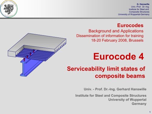
Eurocode 4<br />
<strong>Serviceability</strong> <strong>limit</strong> <strong>state</strong>s of<br />
composite beams<br />
Univ. - Prof. Dr.-Ing. Gerhard Hanswille<br />
Institute for Steel and Composite Structures<br />
University of Wuppertal<br />
Germany<br />
1
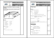
Contents<br />
G. Hanswille<br />
Univ.-Prof. Dr.-Ing.<br />
Institute for Steel and<br />
Composite Structures<br />
University of Wuppertal-Germany<br />
Part 1:<br />
Part 2:<br />
Part 3:<br />
Part 4:<br />
Part 5:<br />
Part 6:<br />
Introduction<br />
Global analysis for serviceability <strong>limit</strong> <strong>state</strong>s<br />
Crack width control<br />
Deformations<br />
Limitation of stresses<br />
Vibrations<br />
2
<strong>Serviceability</strong> <strong>limit</strong> <strong>state</strong>s<br />
G. Hanswille<br />
Univ.-Prof. Dr.-Ing.<br />
Institute for Steel and<br />
Composite Structures<br />
University of Wuppertal-Germany<br />
<strong>Serviceability</strong> <strong>limit</strong> <strong>state</strong>s<br />
Limitation of stresses<br />
Limitation of deflections<br />
crack width control<br />
vibrations<br />
web breathing<br />
3
<strong>Serviceability</strong> <strong>limit</strong> <strong>state</strong>s<br />
G. Hanswille<br />
Univ.-Prof. Dr.-Ing.<br />
Institute for Steel and<br />
Composite Structures<br />
University of Wuppertal-Germany<br />
characteristic combination:<br />
E<br />
{ ∑ G + P + Q + ∑ ψ Q }<br />
d = E k,j k k,1 0,i k, i<br />
frequent combination: Ed<br />
= E { ∑ Gk,j<br />
+ Pk<br />
+ ψ1,1<br />
Qk,1<br />
+ ∑ ψ2,i<br />
Qk,<br />
i }<br />
quasi-permanent combination: Ed<br />
= E { ∑ Gk,j<br />
+ Pk<br />
+ ∑ ψ2,i<br />
Qk,<br />
i }<br />
serviceability <strong>limit</strong> <strong>state</strong>s<br />
E d<br />
≤ C d<br />
:<br />
C d =<br />
- deformation<br />
- crack width<br />
- excessive compressive stresses in concrete<br />
- excessive slip in the interface between steel<br />
and concrete<br />
- excessive creep deformation<br />
- web breathing<br />
- vibrations<br />
4
G. Hanswille<br />
Univ.-Prof. Dr.-Ing.<br />
Institute for Steel and<br />
Composite Structures<br />
University of Wuppertal-Germany<br />
Part 2:<br />
Global analysis for serviceability <strong>limit</strong> <strong>state</strong>s<br />
5
Global analysis - General<br />
G. Hanswille<br />
Univ.-Prof. Dr.-Ing.<br />
Institute for Steel and<br />
Composite Structures<br />
University of Wuppertal-Germany<br />
Calculation of internal forces, deformations and stresses at<br />
serviceability <strong>limit</strong> <strong>state</strong> shall take into account the following<br />
effects:<br />
• shear lag;<br />
• creep and shrinkage of concrete;<br />
• cracking of concrete and tension stiffening of concrete;<br />
• sequence of construction;<br />
• increased flexibility resulting from significant incomplete<br />
interaction due to slip of shear connection;<br />
• inelastic behaviour of steel and reinforcement, if any;<br />
• torsional and distorsional warping, if any.<br />
6
Shear lag- effective width<br />
G. Hanswille<br />
Univ.-Prof. Dr.-Ing.<br />
Institute for Steel and<br />
Composite Structures<br />
University of Wuppertal-Germany<br />
real stress distribution<br />
σ max<br />
σ max<br />
b<br />
shear lag<br />
σ(y)<br />
b<br />
b<br />
ei <<br />
i<br />
0,2<br />
⎡ y ⎤<br />
σ ( y) =σ max ⎢1<br />
−<br />
b<br />
⎥<br />
⎣ i ⎦<br />
4<br />
stresses taking into<br />
account the effective<br />
width<br />
b ei<br />
b ei<br />
σ max<br />
5 b ei<br />
y<br />
b i<br />
b e<br />
The flexibility of steel or<br />
0, 2<br />
σ max<br />
bi<br />
concrete flanges affected by<br />
σ(y)<br />
shear in their plane (shear<br />
⎡b<br />
σ<br />
ei<br />
R = 1,25 ⎢<br />
lag) shall be used either by<br />
⎣ bi<br />
rigorous analysis, or by using<br />
an effective width b e<br />
y<br />
σ (y) =σ R + σ<br />
b i<br />
b<br />
ei ≥<br />
⎤<br />
− 0,2⎥<br />
σ<br />
⎦<br />
[ −σ ]<br />
σ R<br />
max<br />
R<br />
max<br />
⎡<br />
⎢1<br />
−<br />
⎣<br />
y<br />
b<br />
i<br />
⎤<br />
⎥<br />
⎦<br />
4<br />
7
Effective width of concrete flanges<br />
G. Hanswille<br />
Univ.-Prof. Dr.-Ing.<br />
Institute for Steel and<br />
Composite Structures<br />
University of Wuppertal-Germany<br />
L e =0,25 (L 1 + L 2 ) for b eff,2 b b<br />
L e =2L 3 for b e,1 o<br />
b e,2<br />
eff,2<br />
L e =0,85 L 1 for b eff,1<br />
L e =0,70 L 2 for b eff,1<br />
b 1<br />
b o<br />
b 2<br />
L 1 L 2<br />
L 3<br />
L 1 /4 L 1 /2 L 1 /4 L 2 /4 L 2 /2 L 2 /4<br />
b eff,0<br />
b eff,1<br />
b eff,1<br />
b eff,2<br />
end supports: b eff<br />
= b 0<br />
+ β 1<br />
b e,1<br />
+β 2<br />
b e,2<br />
β i<br />
= (0,55+0,025 L e<br />
/b i<br />
) ≤ 1,0<br />
b eff,2<br />
midspan regions and<br />
internal supports:<br />
b eff<br />
= b 0<br />
+ b e,1<br />
+b e,2<br />
b e,i<br />
= L e<br />
/8<br />
L e<br />
– equivalent length<br />
8
Effects of creep of concrete<br />
G. Hanswille<br />
Univ.-Prof. Dr.-Ing.<br />
Institute for Steel and<br />
Composite Structures<br />
University of Wuppertal-Germany<br />
primary effects<br />
Initial sectional<br />
forces<br />
redistribution of the sectional<br />
forces due to creep<br />
M c,o<br />
-M c,r<br />
-z i,c<br />
a st<br />
M L<br />
-N c,o<br />
N c,r<br />
z i,st<br />
M st,o<br />
M st,r<br />
N st,o<br />
-N st,r<br />
The effects of shrinkage and creep of concrete and non-uniform changes of<br />
temperature result in internal forces in cross sections, and curvatures and<br />
longitudinal strains in members; the effects that occur in statically determinate<br />
structures, and in statically indeterminate structures when compatibility of the<br />
deformations is not considered, shall be classified as primary effects.<br />
9
Effects of creep and shrinkage of concrete<br />
G. Hanswille<br />
Univ.-Prof. Dr.-Ing.<br />
Institute for Steel and<br />
Composite Structures<br />
University of Wuppertal-Germany<br />
Types of loading and action effects:<br />
In the following the different types of loading and action effects are distinguished by a<br />
subscript L :<br />
L=P for permanent action effects not changing with time<br />
L=PT<br />
L=S<br />
L=D<br />
time-dependent action effects developing affine to the creep coefficient<br />
action effects caused by shrinkage of concrete<br />
action effects due to prestressing by imposed deformations (e.g. jacking of<br />
supports)<br />
M PT (t=∞)<br />
M PT (t)<br />
time dependent action<br />
effects M L =M PT :<br />
action effects caused by<br />
prestressing due to imposed<br />
deformation M L =M D :<br />
M D<br />
ϕ(t i ,t o )<br />
M PT<br />
(t i<br />
)<br />
ϕ(t ∞ ,t o )<br />
ϕ(t,t o )<br />
M L =M D<br />
+<br />
δ<br />
10
Modular ratios taking into account<br />
effects of creep<br />
G. Hanswille<br />
Univ.-Prof. Dr.-Ing.<br />
Institute for Steel and<br />
Composite Structures<br />
University of Wuppertal-Germany<br />
centroidal axis of the concrete section<br />
z is,L<br />
a st<br />
z st<br />
-z ic,L<br />
z ist,L<br />
z c<br />
z i,L<br />
centroidal axis of the transformed<br />
composite section<br />
centroidal axis of the steel section<br />
(structural steel and reinforcement)<br />
Modular ratios:<br />
E<br />
n L = no[ 1+ ψL<br />
ϕ(t,t<br />
o ) ] no<br />
=<br />
E<br />
a<br />
cm<br />
action<br />
creep multiplier<br />
short term loading Ψ=0<br />
permanent action not changing in time Ψ P<br />
=1,10<br />
shrinkage Ψ S<br />
=0,55<br />
prestressing by controlled imposed deformations Ψ D<br />
=1,50<br />
time-dependent action effects Ψ PT<br />
=0,55<br />
11
Elastic cross-section properties of the<br />
composite section taking into account creep<br />
effects<br />
G. Hanswille<br />
Univ.-Prof. Dr.-Ing.<br />
Institute for Steel and<br />
Composite Structures<br />
University of Wuppertal-Germany<br />
-z ic,L<br />
z ist,L<br />
z c<br />
z i,L<br />
z st<br />
centroidal axis of the<br />
concrete section<br />
centroidal axis of the<br />
composite section<br />
centroidal axis of the<br />
steel section<br />
Modular ratio taking into<br />
account creep effect:<br />
nL=<br />
n0<br />
(1+ ψL<br />
ϕ(t,t<br />
0))<br />
n<br />
o =<br />
Est<br />
E (t<br />
cm<br />
o<br />
)<br />
Transformed cross-section properties of<br />
the concrete section:<br />
Distance between the centroidal axes of<br />
the concrete and the composite section:<br />
A = A / n J = J<br />
c,L<br />
c<br />
L<br />
c,L<br />
c<br />
/ n<br />
L<br />
z = − A<br />
ic,L<br />
st<br />
a<br />
st<br />
/ A<br />
i,L<br />
Transformed cross-section area of the<br />
composite section:<br />
Second moment of area of the<br />
composite section:<br />
A = A + A<br />
i,L<br />
St<br />
c,L<br />
J = J + J +<br />
i,L<br />
st<br />
c,L<br />
A<br />
st<br />
A<br />
c,L<br />
a<br />
2<br />
st<br />
/<br />
A<br />
i,L<br />
12
Effects of cracking of concrete and tension<br />
stiffening of concrete between cracks<br />
G. Hanswille<br />
Univ.-Prof. Dr.-Ing.<br />
Institute for Steel and<br />
Composite Structures<br />
University of Wuppertal-Germany<br />
N s<br />
N sy<br />
mean strain ε sm<br />
=ε s,2<br />
- βΔε s,r<br />
Δε<br />
s<br />
f<br />
= β<br />
ρ<br />
β =0,4<br />
ct,eff<br />
s<br />
E<br />
s<br />
σ c<br />
(x)<br />
σ s<br />
(x)<br />
σ c<br />
(x)<br />
τ v<br />
σ s,2<br />
Δεs = βΔε s,r<br />
ρ<br />
s<br />
= A<br />
s<br />
/ A<br />
c<br />
σ c<br />
(x)<br />
N sm<br />
Δε s,r<br />
fully<br />
cracked<br />
section<br />
ε sr,1<br />
ε sr,2<br />
ε sm,y<br />
ε sy<br />
N s<br />
ε<br />
ε<br />
s,2<br />
σ s<br />
(x)<br />
σ<br />
=<br />
E<br />
s2<br />
s<br />
N s<br />
N s,cr<br />
B C<br />
A<br />
stage A:<br />
stage B:<br />
stage C:<br />
uncracked section<br />
initial crack formation<br />
stabilised crack formation<br />
ε sm<br />
f<br />
E<br />
ct<br />
c<br />
ε s(x)<br />
ε c(x)<br />
βΔε s,r<br />
x<br />
13
Influence of tension stiffening of concrete on<br />
stresses in reinforcement<br />
G. Hanswille<br />
Univ.-Prof. Dr.-Ing.<br />
Institute for Steel and<br />
Composite Structures<br />
University of Wuppertal-Germany<br />
ε sm<br />
N s<br />
equilibrium:<br />
z s<br />
M s<br />
≈0<br />
M<br />
Ma<br />
= M−Ns<br />
a<br />
a<br />
M a ε a<br />
-κ<br />
N<br />
= −<br />
a N s<br />
z a<br />
N a<br />
compatibility:<br />
mean strain in the concrete slab:<br />
ε<br />
sm<br />
= ε<br />
a<br />
+ κa<br />
ε<br />
sm<br />
N<br />
+<br />
s<br />
E A<br />
a<br />
a<br />
N<br />
+<br />
E<br />
s<br />
a<br />
a<br />
A<br />
2<br />
a<br />
=<br />
M a<br />
E<br />
a<br />
J<br />
a<br />
ε s,2<br />
ε s,m<br />
Δε s<br />
=βΔε s,r<br />
mean strain in the concrete<br />
slab:<br />
ε c<br />
ε s<br />
ε<br />
sm<br />
= ε<br />
s2<br />
−βΔε<br />
sr<br />
N<br />
=<br />
s<br />
E A<br />
s<br />
s<br />
f<br />
−β<br />
ρ<br />
ct,eff<br />
s<br />
E<br />
s<br />
14
Redistribution of sectional forces due to tension<br />
stiffening<br />
G. Hanswille<br />
Univ.-Prof. Dr.-Ing.<br />
Institute for Steel and<br />
Composite Structures<br />
University of Wuppertal-Germany<br />
fully cracked section<br />
tension stiffening<br />
z 2 =z st<br />
-z st,s<br />
z st,a<br />
a<br />
N s,2<br />
-M s,2<br />
ΔN ts<br />
-M a,2<br />
+ =<br />
ΔN ts<br />
a<br />
-M s<br />
N s<br />
-M a<br />
-M Ed<br />
-N a,2 -ΔN ts<br />
-N a<br />
N s<br />
α<br />
N sε<br />
st<br />
A<br />
=<br />
A<br />
N s<br />
st<br />
a<br />
J<br />
J<br />
st<br />
a<br />
ΔN<br />
ts<br />
= β<br />
ΔN ts<br />
N s,2<br />
M Ed<br />
f<br />
ct,eff<br />
ρ<br />
M<br />
s<br />
α<br />
A<br />
st<br />
s<br />
N<br />
Sectional forces:<br />
N<br />
a<br />
s<br />
= N<br />
M = M<br />
M<br />
s<br />
= N<br />
a<br />
a2<br />
s2<br />
= M<br />
Ed<br />
+ ΔN<br />
− ΔN<br />
a2<br />
J<br />
J<br />
s<br />
st<br />
ts<br />
ts<br />
+ ΔN<br />
= M<br />
= M<br />
ts<br />
a<br />
Ed<br />
Ed<br />
A<br />
A<br />
a<br />
= M<br />
s<br />
J<br />
J<br />
z<br />
Ed<br />
st<br />
z<br />
st<br />
st,s<br />
st,a<br />
J st = J 2<br />
J<br />
J<br />
a<br />
st<br />
+ ΔN<br />
− ΔN<br />
ts<br />
+ ΔN<br />
ts<br />
ts<br />
a<br />
15
G. Hanswille<br />
Stresses taking into account tension stiffening of<br />
Univ.-Prof. Dr.-Ing.<br />
Institute for Steel and<br />
concrete<br />
Composite Structures<br />
University of Wuppertal-Germany<br />
fully cracked<br />
tension stiffening<br />
N s<br />
N s,2<br />
-M s,2<br />
ΔN ts<br />
-M s<br />
z st<br />
z st,a<br />
a<br />
-M a,2<br />
+ =<br />
ΔN ts<br />
a<br />
-M a<br />
-M Ed<br />
-z st,s<br />
st<br />
z a<br />
-N a,2 -ΔN ts<br />
-N a<br />
σ<br />
reinforcement:<br />
s<br />
=<br />
σ<br />
s,2<br />
+ β<br />
f<br />
ρ<br />
ctm<br />
s<br />
α<br />
st<br />
structural steel:<br />
σ<br />
a<br />
=<br />
σ<br />
a,2<br />
ΔN<br />
−<br />
A<br />
ts<br />
a<br />
+<br />
ΔN<br />
J<br />
ts<br />
a<br />
a<br />
z<br />
a<br />
α<br />
st<br />
=<br />
A<br />
A<br />
st<br />
a<br />
J<br />
J<br />
st<br />
a<br />
σ<br />
s<br />
=<br />
M<br />
J<br />
Ed<br />
st<br />
z<br />
st,s<br />
+<br />
β<br />
f<br />
ρ<br />
ctm<br />
s<br />
α<br />
st<br />
σ<br />
a<br />
=<br />
M<br />
J<br />
Ed<br />
st<br />
z<br />
st<br />
−<br />
ΔN<br />
A<br />
ts<br />
a<br />
+<br />
ΔN<br />
J<br />
ts<br />
a<br />
a<br />
z<br />
a<br />
ΔN<br />
ts<br />
=<br />
β<br />
f<br />
ρ<br />
ctm<br />
s<br />
A<br />
α<br />
s<br />
16
G. Hanswille<br />
Univ.-Prof. Dr.-Ing.<br />
Influence of tension stiffening on flexural stiffness<br />
Institute for Steel and<br />
Composite Structures<br />
University of Wuppertal-Germany<br />
N s<br />
ε sm<br />
Curvature:<br />
z st<br />
a<br />
-M s<br />
-M a<br />
-M<br />
κ<br />
-N a<br />
ε a<br />
κ =<br />
E<br />
st<br />
M<br />
I<br />
2,ts<br />
M<br />
=<br />
a<br />
E J<br />
st<br />
a<br />
Effective flexural<br />
stiffness:<br />
M−<br />
N<br />
=<br />
E J<br />
st<br />
s<br />
a<br />
a<br />
M<br />
EJ<br />
E<br />
st<br />
J<br />
2,ts<br />
=<br />
Ea<br />
Ja<br />
(Ns<br />
− N<br />
1−<br />
M<br />
s, ε<br />
)<br />
a<br />
E st<br />
J 2<br />
E st<br />
J 2,ts<br />
E st<br />
J 1<br />
κ<br />
E st J 1<br />
E st J 2,ts<br />
E st J 2<br />
M R<br />
M Rn<br />
M<br />
E st J 1 uncracked section<br />
E st J 2 fully cracked section<br />
E st J 2,ts effective flexural<br />
stiffness taking into<br />
account tension<br />
stiffening of concrete<br />
17
Effects of cracking of concrete - General<br />
method according to EN 1994-1-1<br />
G. Hanswille<br />
Univ.-Prof. Dr.-Ing.<br />
Institute for Steel and<br />
Composite Structures<br />
University of Wuppertal-Germany<br />
E a<br />
J 1<br />
E a<br />
J 2<br />
– un-cracked flexural stiffness<br />
– cracked flexural stiffness<br />
L 1 L 2<br />
L1,cr L 2,cr<br />
E a J 1 E a J E a J 1<br />
2<br />
ΔM<br />
• Determination of internal forces by uncracked<br />
analysis for the characteristic<br />
combination.<br />
• Determination of the cracked regions<br />
with the extreme fibre concrete tensile<br />
stress σ c,max = 2,0 f ct,m .<br />
• Reduction of flexural stiffness to E a J 2 in<br />
the cracked regions.<br />
• New structural analysis for the new<br />
distribution of flexural stiffness.<br />
cracked analysis<br />
un-cracked analysis<br />
ΔM Redistribution of<br />
bending moments due to<br />
cracking of concrete<br />
18
Effects of cracking of concrete –<br />
simplified method<br />
G. Hanswille<br />
Univ.-Prof. Dr.-Ing.<br />
Institute for Steel and<br />
Composite Structures<br />
University of Wuppertal-Germany<br />
L 1<br />
L 2<br />
0,15 L 1 0,15 L 2<br />
E a<br />
J 1<br />
L<br />
min<br />
E a<br />
J 2<br />
/L ≥0,<br />
6<br />
max<br />
ΔM II<br />
For continuous composite beams with<br />
the concrete flanges above the steel<br />
section and not pre-stressed, including<br />
beams in frames that resist horizontal<br />
forces by bracing, a simplified method<br />
may be used. Where all the ratios of<br />
the length of adjacent continuous<br />
spans (shorter/longer) between<br />
supports are at least 0,6, the effect of<br />
cracking may be taken into account by<br />
using the flexural stiffness E a J 2 over<br />
15% of the span on each side of each<br />
internal support, and as the uncracked<br />
values E a J 1 elsewhere.<br />
19
G. Hanswille<br />
Univ.-Prof. Dr.-Ing.<br />
Institute for Steel and<br />
Composite Structures<br />
University of Wuppertal-Germany<br />
Part 3:<br />
Limitation of crack width<br />
20
Control of cracking<br />
G. Hanswille<br />
Univ.-Prof. Dr.-Ing.<br />
Institute for Steel and<br />
Composite Structures<br />
University of Wuppertal-Germany<br />
General considerations<br />
minimum reinforcement<br />
If crack width control is required, a minimum amount of bonded<br />
reinforcement is required to control cracking in areas where tension due to<br />
restraint and or direct loading is expected. The amount may be estimated<br />
from equilibrium between the tensile force in concrete just before cracking<br />
and the tensile force in the reinforcement at yielding or at a lower stress if<br />
necessary to <strong>limit</strong> the crack width. According to Eurocode 4-1-1 the<br />
minimum reinforcement should be placed, where under the characteristic<br />
combination of actions, stresses in concrete are tensile.<br />
control of cracking due to direct loading<br />
Where at least the minimum reinforcement is provided, the <strong>limit</strong>ation of<br />
crack width for direct loading may generally be achieved by <strong>limit</strong>ing bar<br />
spacing or bar diameters. Maximum bar spacing and maximum bar<br />
diameter depend on the stress σ s<br />
in the reinforcement and the design<br />
crack width.<br />
21
Recommended values for w max<br />
G. Hanswille<br />
Univ.-Prof. Dr.-Ing.<br />
Institute for Steel and<br />
Composite Structures<br />
University of Wuppertal-Germany<br />
Exposure<br />
class<br />
reinforced members, prestressed<br />
members with unbonded tendons<br />
and members prestressed by<br />
controlled imposed deformations<br />
quasi - permanent<br />
load combination<br />
prestressed members with<br />
bonded tendons<br />
frequent load combination<br />
XO, XC1 0,4 mm (1) 0,2 mm<br />
XC2, XC3,XC4 0,2 mm (2)<br />
0,3 mm<br />
XD1,XD2,XS1,<br />
XS2,XS3<br />
decompression<br />
(1) For XO and XC1 exposure classes, crack width has no influence on<br />
durability and this <strong>limit</strong> is set to guarantee acceptable appearance. In<br />
absence of appearance conditions this <strong>limit</strong> may be relaxed.<br />
(2) For these exposure classes, in addition, decompression should be<br />
checked under the quasi-permanent combination of loads.<br />
22
Exposure classes according to EN 1992-1-1<br />
(risk of corrosion of reinforcement)<br />
G. Hanswille<br />
Univ.-Prof. Dr.-Ing.<br />
Institute for Steel and<br />
Composite Structures<br />
University of Wuppertal-Germany<br />
Class Description of environment Examples<br />
XO<br />
for concrete without reinforcement, for<br />
concrete with reinforcement : very dry<br />
no risk of corrosion or attack<br />
concrete inside buildings with very low air humidity<br />
Corrosion induced by carbonation<br />
XC1 dry or permanently wet concrete inside buildings with low air humidity<br />
XC2 wet, rarely dry concrete surfaces subjected to long term water contact, foundations<br />
XC3 moderate humidity external concrete sheltered from rain<br />
XC4 cyclic wet and dry concrete surfaces subject to water contact not within class XC2<br />
Corrosion induced by chlorides<br />
XD1 moderate humidity concrete surfaces exposed to airborne chlorides<br />
XD2 wet, rarely dry swimming pools, members exposed to industrial waters containing<br />
chlorides<br />
XD3 cyclic wet and dry car park slabs, pavements, parts of bridges exposed to spray containing<br />
Corrosion induced by chlorides from sea water<br />
XS1 exposed to airborne salt structures near to or on the coast<br />
XS2 permanently submerged parts of marine structures<br />
XS3 tidal, splash and spray zones parts of marine structures<br />
23
N s<br />
ε<br />
σ<br />
σ c,1<br />
Cracking of concrete (initial crack formation)<br />
L es<br />
σ c,1<br />
w<br />
ε s<br />
ε c<br />
L es<br />
σ s<br />
σ s,1<br />
L es<br />
L es<br />
σ s,1<br />
σ s,2<br />
L es<br />
ρ<br />
Δσ s<br />
s<br />
A<br />
=<br />
A<br />
s<br />
c<br />
N s<br />
Equilibrium in longitudinal direction:<br />
σ<br />
s<br />
A<br />
A s<br />
ρ s<br />
f ctm<br />
s<br />
=<br />
σ<br />
s,1<br />
A<br />
s<br />
+ σ<br />
c,1<br />
A<br />
c<br />
G. Hanswille<br />
Univ.-Prof. Dr.-Ing.<br />
Institute for Steel and<br />
Composite Structures<br />
University of Wuppertal-Germany<br />
Compatibility at the end of the introduction<br />
length:<br />
σs,1<br />
σc,1<br />
εs,1<br />
=εc,1<br />
⇒ =<br />
E E<br />
σs,1<br />
=<br />
σs<br />
⎡<br />
⎢<br />
⎣<br />
s<br />
c<br />
ρs<br />
no<br />
⎤<br />
1+ ρ<br />
⎥<br />
s no<br />
⎦<br />
s<br />
o<br />
E<br />
n o =<br />
E<br />
Change of stresses in reinforcement<br />
due to cracking:<br />
σ<br />
Δσ<br />
s<br />
s = σs<br />
− σs,1<br />
=<br />
1+<br />
ρ n<br />
N<br />
s,r<br />
= f<br />
ctm<br />
A<br />
c<br />
( 1+<br />
ρ n )<br />
s<br />
o<br />
cross-section area of reinforcement<br />
reinforcement ratio<br />
mean value of tensile strength of concrete<br />
s<br />
c<br />
24
N s<br />
ε<br />
Cracking of concrete – introduction length<br />
w<br />
ε s<br />
N s<br />
Change of stresses in reinforcement<br />
due to cracking:<br />
σ<br />
Δσ<br />
s<br />
s = σs<br />
− σs,1<br />
=<br />
1+<br />
ρs<br />
no<br />
Equilibrium in longitudinal direction<br />
G. Hanswille<br />
Univ.-Prof. Dr.-Ing.<br />
Institute for Steel and<br />
Composite Structures<br />
University of Wuppertal-Germany<br />
σ<br />
L es<br />
ε c<br />
L es<br />
Δσ s<br />
L<br />
L<br />
es<br />
es<br />
U<br />
π<br />
s<br />
d<br />
τ<br />
s<br />
sm<br />
τ<br />
= Δσs<br />
As<br />
πd<br />
= Δσs<br />
4<br />
sm<br />
2<br />
s<br />
introduction length L Es<br />
ρ<br />
s<br />
A<br />
=<br />
A<br />
s<br />
c<br />
σ c,1<br />
σ s<br />
σ s,1<br />
L es<br />
L es<br />
L<br />
es<br />
=<br />
σs<br />
d<br />
4 τ<br />
s<br />
sm<br />
1<br />
1+<br />
n ρ<br />
o<br />
s<br />
E<br />
n o =<br />
E<br />
s<br />
c<br />
σ c,1<br />
σ s,1<br />
σ s,2<br />
L es<br />
τ sm<br />
U s<br />
A s<br />
ρ s<br />
τ sm<br />
-perimeter of the bar<br />
-cross-section area<br />
-reinforcement ratio<br />
-mean bond strength<br />
crack width<br />
w = 2L<br />
es<br />
( ε<br />
sm<br />
−<br />
ε<br />
cm<br />
)<br />
25
N s<br />
ε<br />
ε s,m<br />
ε c,m<br />
Determination of the mean strains of<br />
reinforcement and concrete in the stage of initial<br />
crack formation<br />
w<br />
ε s<br />
(x)<br />
ε c<br />
(x)<br />
Δε s,cr<br />
N s<br />
ε cr<br />
ε s<br />
Mean bond strength:<br />
τs,m<br />
=<br />
Les<br />
σ<br />
s,m<br />
=<br />
L<br />
∫<br />
o<br />
1 Es<br />
σ<br />
s<br />
−β<br />
τs<br />
(x)dx<br />
Δσ<br />
s<br />
⇒ β<br />
G. Hanswille<br />
Univ.-Prof. Dr.-Ing.<br />
Institute for Steel and<br />
Composite Structures<br />
University of Wuppertal-Germany<br />
≈ 1,8 fctm<br />
Mean stress in the reinforcement:<br />
=<br />
σ<br />
s<br />
− Δσ<br />
Δσ<br />
s<br />
sm<br />
σ<br />
σ s,m<br />
L es<br />
σ s (x)<br />
L es<br />
βΔσ s<br />
Δσ s<br />
σ s σ s,1<br />
σ c,1<br />
L es<br />
L es<br />
1<br />
Δσsm=<br />
Les<br />
L es<br />
∫<br />
0<br />
Δσs(x)<br />
dx<br />
4 x<br />
Δσs(x)<br />
= ∫ τ<br />
s 0 s (x) dx<br />
U<br />
Mean strains in reinforcement and concrete:<br />
ε<br />
s,m<br />
εc,m<br />
=<br />
=<br />
ε<br />
s,2<br />
β εcr<br />
−<br />
β<br />
Δε<br />
s,cr<br />
x<br />
26
N s<br />
Determination of initial crack width<br />
w<br />
N s<br />
crack width<br />
G. Hanswille<br />
Univ.-Prof. Dr.-Ing.<br />
Institute for Steel and<br />
Composite Structures<br />
University of Wuppertal-Germany<br />
ε<br />
ε s,m<br />
ε s<br />
(x)<br />
ε c<br />
(x)<br />
ε s,2<br />
Δε s,cr<br />
w = 2L<br />
es<br />
( ε<br />
sm<br />
− ε<br />
cm<br />
εs ,m − εcm<br />
= ( 1− β)<br />
εs,2<br />
)<br />
ε c,m<br />
ε cr<br />
L es<br />
L es<br />
L<br />
es<br />
=<br />
σs<br />
d<br />
4 τ<br />
s<br />
sm<br />
1<br />
1+<br />
n ρ<br />
o<br />
s<br />
σ s<br />
τsm<br />
≈ 1,8 f ctm<br />
σ s,m<br />
βΔσ s<br />
Δσ s<br />
L es<br />
L es<br />
σ s<br />
σ s,1<br />
σ c,1<br />
x<br />
2<br />
(1− β)<br />
σs<br />
d<br />
w =<br />
s<br />
2 τsm<br />
Es<br />
1<br />
1+<br />
no<br />
ρs<br />
with β= 0,6 for short term loading und<br />
β= 0,4 for long term loading<br />
27
Maximum bar diameters acc. to EC4<br />
G. Hanswille<br />
Univ.-Prof. Dr.-Ing.<br />
Institute for Steel and<br />
Composite Structures<br />
University of Wuppertal-Germany<br />
σ s<br />
[N/mm 2 ]<br />
maximum bar diameter<br />
d ∗ s<br />
for<br />
w k = 0,4 w k = 0,3 w k = 0,2<br />
160 40 32 25<br />
200 32 25 16<br />
240 20 16 12<br />
280 16 12 8<br />
320 12 10 6<br />
360 10 8 5<br />
400 8 6 4<br />
Crack width w:<br />
sm<br />
2<br />
s<br />
(1 − β)<br />
σ d<br />
w =<br />
2 τ E<br />
s<br />
s<br />
1<br />
1+<br />
n ρ<br />
Maximum bar diameter for a<br />
required crack width w:<br />
d<br />
s<br />
=<br />
w<br />
2 τ<br />
sm<br />
σ<br />
E<br />
s<br />
2<br />
s<br />
o<br />
s<br />
(1+<br />
n<br />
(1− β)<br />
o<br />
≈<br />
ρ<br />
s<br />
6<br />
)<br />
f<br />
σ<br />
2<br />
s<br />
ct,m<br />
With τ sm<br />
= 1,8 f ct,mo<br />
and the reference<br />
value for the mean tensile strength of<br />
concrete f ctm,o<br />
= 2,9 N/mm 2 follows:<br />
d<br />
s<br />
E<br />
s<br />
450 6 5 -<br />
β= 0,4 for long term loading and<br />
repeated loading<br />
d<br />
d<br />
*<br />
s<br />
*<br />
s<br />
=<br />
w<br />
k<br />
w<br />
≈ 6<br />
k<br />
3,6<br />
f<br />
f<br />
ctm,o<br />
2<br />
σs<br />
ctm,o<br />
2<br />
σs<br />
E<br />
s<br />
E<br />
s<br />
(1+<br />
n<br />
(1− β)<br />
o<br />
ρ<br />
s<br />
)<br />
28
Crack width for stabilised crack formation<br />
G. Hanswille<br />
Univ.-Prof. Dr.-Ing.<br />
Institute for Steel and<br />
Composite Structures<br />
University of Wuppertal-Germany<br />
f<br />
E<br />
N s<br />
ct<br />
c<br />
ε<br />
ε<br />
s,2<br />
ε s(x)<br />
ε c(x)<br />
σ<br />
=<br />
E<br />
s2<br />
s<br />
s r,max<br />
= 2 L es<br />
w<br />
β= 0,6 for short term loading<br />
β= 0,4 for long term loading and<br />
repeated loading<br />
Crack width for high bond bars<br />
w = sr,max<br />
( εsm<br />
− εcm)<br />
Mean strain of reinforcement and<br />
concrete:<br />
εs,m<br />
= εs,2<br />
− β Δ εs<br />
A<br />
ε s(x)<br />
- ε<br />
c fctm<br />
f<br />
c(x) εs,m<br />
= εs,2<br />
− β = εs,2<br />
− β<br />
Es<br />
As<br />
Es<br />
ρ<br />
f<br />
ε<br />
ctm<br />
cm =β<br />
Ec<br />
s r,min<br />
= L es<br />
ε<br />
sm<br />
− ε<br />
cm<br />
=<br />
σ<br />
E<br />
s<br />
s<br />
f<br />
− β<br />
E<br />
ctm<br />
s<br />
ρ<br />
s<br />
(1+<br />
n<br />
o<br />
ρ<br />
s<br />
ctm<br />
)<br />
s<br />
29
Crack width for stabilised crack formation<br />
G. Hanswille<br />
Univ.-Prof. Dr.-Ing.<br />
Institute for Steel and<br />
Composite Structures<br />
University of Wuppertal-Germany<br />
N s<br />
w<br />
The maximum crack spacing s r,max<br />
in the<br />
stage of stabilised crack formation is twice<br />
the introduction length L es<br />
.<br />
ε<br />
ε<br />
s,2<br />
=<br />
σ<br />
E<br />
s<br />
s<br />
w = s<br />
r,max<br />
( ε<br />
sm<br />
−<br />
ε<br />
cm<br />
)<br />
ε s(x)<br />
ε c(x)<br />
f<br />
E<br />
ct<br />
c<br />
ε s(x)<br />
- ε c(x)<br />
L<br />
es<br />
=<br />
f<br />
U<br />
ctm<br />
s<br />
A<br />
τ<br />
c<br />
sm<br />
f<br />
=<br />
ρ<br />
ctm<br />
s<br />
4<br />
τ<br />
d<br />
s<br />
sm<br />
maximum crack width for s r<br />
= s r,max<br />
s r,max<br />
= 2 L es<br />
s r,min<br />
= L es<br />
β= 0,6 for short term loading<br />
β= 0,4 for long term loading and<br />
repeated loading<br />
= f d ⎛ σ f<br />
⎞<br />
w<br />
ctm s<br />
⎜ s<br />
− β<br />
ctm<br />
(1+<br />
no<br />
ρs<br />
⎟<br />
2 τ ρ ⎝ E ρ E<br />
)<br />
sm s s s s ⎠<br />
30
Crack width and crack spacing according<br />
Eurocode 2<br />
G. Hanswille<br />
Univ.-Prof. Dr.-Ing.<br />
Institute for Steel and<br />
Composite Structures<br />
University of Wuppertal-Germany<br />
Crack width<br />
w = s<br />
r,max<br />
( ε<br />
sm<br />
−<br />
ε<br />
cm<br />
)<br />
ε<br />
sm<br />
− ε<br />
cm<br />
=<br />
σ<br />
E<br />
s<br />
s<br />
−<br />
β<br />
f<br />
E<br />
ctm<br />
s<br />
ρ<br />
s<br />
(1+<br />
n<br />
o<br />
ρ<br />
s<br />
)<br />
≥<br />
0,6<br />
σ<br />
E<br />
s<br />
s<br />
β= 0,6 for short term loading<br />
β= 0,4 for long term loading and repeated loading<br />
Crack spacing<br />
In Eurocode 2 for the maximum crack spacing a semiempirical<br />
equation based on test results is given<br />
s<br />
s<br />
r,max = 3,4c + k1⋅<br />
k2<br />
⋅0,425<br />
d s<br />
-diameter of the bar<br />
ρs<br />
d<br />
c- concrete cover<br />
k 1<br />
k 2<br />
coefficient taking into account bond properties of<br />
the reinforcement with k 1<br />
=o,8 for high bond bars<br />
coefficient which takes into account the distribution<br />
of strains (1,0 for pur tension and 0,5 for bending)<br />
31
Determination of the cracking moment M cr and<br />
the normal force of the concrete slab in the<br />
stage of initial cracking<br />
G. Hanswille<br />
Univ.-Prof. Dr.-Ing.<br />
Institute for Steel and<br />
Composite Structures<br />
University of Wuppertal-Germany<br />
h c<br />
cracking moment M cr<br />
z o<br />
z i,st<br />
N c+s<br />
z io<br />
a st<br />
M<br />
M<br />
cr<br />
cr<br />
cracking moment M cr<br />
:<br />
σc<br />
+ σc,<br />
ε = ct,eff =<br />
M c+s<br />
σ c<br />
M cr<br />
=<br />
=<br />
[ f − σ ]<br />
ct,eff<br />
[ f − σ ]<br />
ct,eff<br />
f<br />
c, ε<br />
c, ε<br />
k<br />
z<br />
z<br />
1<br />
n<br />
o<br />
f<br />
ctm<br />
o<br />
J<br />
+ h<br />
ic,o<br />
c<br />
n<br />
io<br />
/ 2<br />
o<br />
(1+<br />
h<br />
J<br />
c<br />
io<br />
/(2<br />
z<br />
o<br />
)<br />
primary effects due to shrinkage<br />
M c,ε<br />
N c,ε<br />
σ cε<br />
sectional normal force of the concrete<br />
slab:<br />
N<br />
N<br />
cr<br />
cr<br />
= M<br />
=<br />
A<br />
cr<br />
c<br />
(f<br />
A<br />
co<br />
ct,eff<br />
zo<br />
+ A<br />
J<br />
1+<br />
h<br />
− σ<br />
c<br />
io<br />
s<br />
c, ε<br />
/(2<br />
)<br />
z<br />
is<br />
+ N<br />
c+<br />
s, ε<br />
( 1+ ρ n )<br />
z<br />
o<br />
)<br />
s<br />
o<br />
+ N<br />
c+<br />
s, ε<br />
N<br />
cr<br />
= A<br />
c<br />
f<br />
ct,eff<br />
(1+ ρ<br />
s<br />
n<br />
0<br />
)<br />
⎡<br />
⎢<br />
⎢<br />
⎢<br />
⎢<br />
⎣<br />
1 +<br />
h<br />
c<br />
k c<br />
k c,ε<br />
≈ 0,3<br />
1<br />
/(2<br />
z<br />
o<br />
)<br />
+<br />
N<br />
c+<br />
s, ε<br />
A<br />
c<br />
−<br />
f<br />
A<br />
c<br />
ct,eff<br />
σ<br />
c, ε<br />
( 1+ ρ n )<br />
1+<br />
hc<br />
/(2 zo<br />
)<br />
(1 + ρ n )<br />
s<br />
s<br />
0<br />
o<br />
⎤<br />
⎥<br />
⎥<br />
⎥<br />
⎥<br />
⎦<br />
32
Simplified solution for the cracking moment<br />
and the normal force in the concrete slab<br />
G. Hanswille<br />
Univ.-Prof. Dr.-Ing.<br />
Institute for Steel and<br />
Composite Structures<br />
University of Wuppertal-Germany<br />
cracking moment M cr<br />
M c+s<br />
σ c<br />
simplified solution for the normal<br />
force in the concrete slab:<br />
h c<br />
z o<br />
z i,st<br />
N c+s<br />
M cr<br />
N<br />
cr<br />
≈<br />
A<br />
c<br />
f<br />
ctm<br />
k<br />
s<br />
⋅k<br />
⋅k<br />
c<br />
primary effects due to shrinkage<br />
k = 0,8<br />
k s = 0,9<br />
coefficient taking into account the effect of<br />
non-uniform self-equilibrating stresses<br />
coefficient taking into account the slip<br />
effects of shear connection<br />
M c+s,ε<br />
N c+s,ε<br />
σ cε<br />
k<br />
c<br />
=<br />
1+<br />
1<br />
hc<br />
2 z<br />
o<br />
+<br />
0,3<br />
≤1,0<br />
cracking moment<br />
shrinkage<br />
33
Determination of minimum reinforcement<br />
G. Hanswille<br />
Univ.-Prof. Dr.-Ing.<br />
Institute for Steel and<br />
Composite Structures<br />
University of Wuppertal-Germany<br />
M c<br />
M c,ε<br />
A<br />
s<br />
h c<br />
z o<br />
o<br />
N c<br />
M cr<br />
N c,ε<br />
z i,o<br />
cracking<br />
moment<br />
shrinkage<br />
M a,ε<br />
N a,ε<br />
Ac<br />
fct,eff<br />
1<br />
≥ k ks<br />
kc<br />
kc<br />
= + 0,3 ≤ 1, 0<br />
σ<br />
1+<br />
h z<br />
s<br />
c<br />
o<br />
d<br />
s<br />
= d<br />
∗<br />
s<br />
f<br />
ct,eff<br />
f<br />
ct,<br />
f cto = 2,9 N/mm 2<br />
k = 0,8<br />
k s = 0,9<br />
k c<br />
d ∗ s<br />
d s<br />
Influence of non linear residual stresses due to shrinkage and temperature effects<br />
flexibility of shear connection<br />
Influence of distribution of tensile stresses in concrete immediately prior to<br />
cracking<br />
maximum bar diameter<br />
modified bar diameter for other concrete strength classes<br />
σ s stress in reinforcement acc. to Table 1<br />
effective concrete tensile strength<br />
f ct,eff<br />
34
Control of cracking due to direct loading –<br />
Verification by <strong>limit</strong>ing bar spacing or bar diameter<br />
G. Hanswille<br />
Univ.-Prof. Dr.-Ing.<br />
Institute for Steel and<br />
Composite Structures<br />
University of Wuppertal-Germany<br />
A c<br />
fully cracked tension stiffening<br />
N s,2<br />
-z st,s<br />
-M s,2 -M s<br />
ΔN ts<br />
N s<br />
z st<br />
z st,a<br />
a<br />
-M a,2<br />
+ =<br />
ΔN ts<br />
a<br />
-M a<br />
-M Ed<br />
A s<br />
A a<br />
z a<br />
-N a,2 -ΔN ts<br />
-N a<br />
The calculation of stresses is<br />
based on the mean strain in the<br />
concrete slab. The factor β<br />
results from the mean value of<br />
crack spacing. With s rm ≈ 2/3<br />
s r,max results β ≈2/3 ·0,6 = 0,4<br />
stresses in reinforcement<br />
taking into account tension<br />
stiffening for the bending<br />
moment M Ed<br />
of the quasi<br />
permanent combination:<br />
A<br />
ρ<br />
s<br />
s = β =0,4<br />
A<br />
c<br />
σ<br />
σ<br />
s<br />
s<br />
= σ<br />
=<br />
M<br />
α<br />
s,2<br />
J<br />
st<br />
Ed<br />
2<br />
+<br />
z<br />
A<br />
=<br />
A<br />
2<br />
a<br />
Δσ<br />
st,s<br />
J<br />
J<br />
2<br />
a<br />
ts<br />
+<br />
β<br />
f<br />
ρ<br />
ct,eff<br />
s<br />
α<br />
st<br />
The bar diameter or the bar spacing has to be <strong>limit</strong>ed<br />
35
Maximum bar diameters and maximum bar<br />
spacing for high bond bars acc. to EC4<br />
G. Hanswille<br />
Univ.-Prof. Dr.-Ing.<br />
Institute for Steel and<br />
Composite Structures<br />
University of Wuppertal-Germany<br />
Table 1: Maximum bar diameter<br />
Table 2: Maximum bar spacing<br />
σ s<br />
[N/mm 2 ]<br />
maximum bar diameter<br />
d ∗ s<br />
for<br />
w k = 0,4 w k = 0,3 w k = 0,2<br />
160 40 32 25<br />
200 32 25 16<br />
240 20 16 12<br />
280 16 12 8<br />
320 12 10 6<br />
360 10 8 5<br />
400 8 6 4<br />
450 6 5 -<br />
σ s<br />
[N/mm 2 ]<br />
160<br />
200<br />
240<br />
280<br />
320<br />
360<br />
maximum bar spacing in [mm]<br />
for<br />
w k = 0,4<br />
300<br />
300<br />
250<br />
200<br />
150<br />
100<br />
w k = 0,3<br />
300<br />
250<br />
200<br />
150<br />
100<br />
50<br />
w k = 0,2<br />
200<br />
150<br />
100<br />
50<br />
-<br />
-<br />
36
Direct calculation of crack width w for<br />
composite sections based on EN 1992-2<br />
G. Hanswille<br />
Univ.-Prof. Dr.-Ing.<br />
Institute for Steel and<br />
Composite Structures<br />
University of Wuppertal-Germany<br />
A s<br />
-M s<br />
N s<br />
-M a<br />
σ s,<br />
M Ed<br />
-z st,s<br />
z st<br />
crack width for high bond bars:<br />
σ<br />
α<br />
s<br />
st<br />
=<br />
M<br />
J<br />
A<br />
=<br />
A<br />
Ed<br />
st<br />
st<br />
a<br />
J<br />
J<br />
a<br />
z<br />
st<br />
st,s<br />
+ β<br />
f<br />
ρ<br />
ct,eff<br />
s<br />
c<br />
α<br />
st<br />
A<br />
ρ<br />
s<br />
s = β = 0, 4<br />
A<br />
w = s<br />
ε<br />
s<br />
sm<br />
r,max<br />
− ε<br />
r,max<br />
cm<br />
-N a<br />
( εsm<br />
− εcm)<br />
σs<br />
f<br />
− β<br />
ctm<br />
E E ρ<br />
s<br />
=<br />
s<br />
= 3,4c + 0,34<br />
s<br />
d<br />
ρ<br />
s<br />
s<br />
s<br />
(1+<br />
n<br />
o<br />
ρ<br />
s<br />
)<br />
≥<br />
0,6<br />
σ<br />
E<br />
s<br />
c - concrete cover of reinforcement<br />
37
Stresses in reinforcement in case of bonded<br />
tendons – initial crack formation<br />
G. Hanswille<br />
Univ.-Prof. Dr.-Ing.<br />
Institute for Steel and<br />
Composite Structures<br />
University of Wuppertal-Germany<br />
σ s,1<br />
Δσ p1<br />
A p , d p<br />
A s , d s<br />
Equilibrium at the crack:<br />
σs<br />
As<br />
+ Δσp<br />
Ap<br />
= N=<br />
σ<br />
σ s =σ s1 +Δσ s As<br />
= π ds<br />
τsm<br />
L<br />
s<br />
σ p<br />
Δσp<br />
Ap<br />
= π dp<br />
τpm<br />
L<br />
N<br />
σs<br />
− σs1<br />
δs<br />
= δp<br />
⇒ Les<br />
=<br />
Es<br />
Δσ s<br />
Δσ p<br />
Stresses:<br />
N<br />
L es<br />
σs<br />
=<br />
Δσp<br />
As<br />
+ ξ1<br />
Ap<br />
L ep<br />
τ pm τ sm<br />
τ<br />
σ p =σ po +σ p1 +Δσ p<br />
f<br />
ct,eff<br />
Equilibrium in longitudinal direction:<br />
e,s<br />
ep<br />
Compatibility at the crack:<br />
ξ<br />
1<br />
=<br />
τ<br />
pm<br />
sm<br />
d<br />
d<br />
s<br />
v<br />
Δσ<br />
p<br />
=<br />
A<br />
E<br />
p<br />
A<br />
c<br />
− Δσ<br />
s<br />
ξ<br />
1<br />
+ ξ<br />
(1+<br />
n<br />
p1<br />
With E s ≈E p and σ s1 =Δσ p1 =0 results:<br />
N<br />
1<br />
L<br />
A<br />
ep<br />
p<br />
o<br />
ρ<br />
tot<br />
)<br />
38
Stresses in reinforcement for final crack<br />
formation<br />
G. Hanswille<br />
Univ.-Prof. Dr.-Ing.<br />
Institute for Steel and<br />
Composite Structures<br />
University of Wuppertal-Germany<br />
Δσ p2<br />
σ s2<br />
Δσ p2<br />
Δσ p1<br />
σ s1<br />
σ s<br />
A s , d s<br />
A p , d p<br />
σ c<br />
σ c =f ct,eff<br />
x<br />
Equilibrium at the crack:<br />
N − P<br />
Maximum crack spacing:<br />
f<br />
s<br />
ct<br />
δ<br />
s<br />
A<br />
r,max<br />
σ<br />
c<br />
s2<br />
o<br />
= δ<br />
s<br />
=<br />
d<br />
=<br />
2τ<br />
− σ<br />
=σ<br />
p<br />
r,max<br />
=<br />
2<br />
s1<br />
s2<br />
sm<br />
σ<br />
s<br />
s<br />
=<br />
s2<br />
A<br />
[ τ n d π + τ n d π ]<br />
f<br />
(A<br />
sm<br />
ct,eff<br />
s<br />
r,max<br />
s<br />
A<br />
+ ξ<br />
c<br />
2<br />
U<br />
A<br />
− β( σs2<br />
− σs1)<br />
Δσp,2<br />
− β(<br />
Δσp2<br />
− Δσ<br />
=<br />
E<br />
E<br />
s<br />
s<br />
A<br />
Compatibility at the crack:<br />
s<br />
2<br />
+ Δ σ<br />
s<br />
s<br />
p2<br />
p<br />
τ<br />
)<br />
sm<br />
pm<br />
Equilibrium in longitudinal direction:<br />
A<br />
p<br />
σ<br />
p2<br />
p<br />
p<br />
− σ<br />
p1<br />
s<br />
=<br />
r,max<br />
2<br />
p<br />
U<br />
A<br />
p<br />
p<br />
τ<br />
pm<br />
p1<br />
)<br />
s r,max<br />
mean crack spacing: s r,m ≈2/3 s r,max<br />
39
Determination of stresses in composite<br />
sections with bonded tendons<br />
G. Hanswille<br />
Univ.-Prof. Dr.-Ing.<br />
Institute for Steel and<br />
Composite Structures<br />
University of Wuppertal-Germany<br />
A p<br />
A s<br />
-z st,s<br />
σ s,<br />
σ p<br />
M Ed<br />
Stresses σ * s in reinforcement<br />
at the crack location<br />
neglecting different bond<br />
behaviour of reinforcement<br />
and tendons:<br />
z st<br />
Stresses in reinforcement taking into account the<br />
different bond behaviour:<br />
σ<br />
*<br />
s<br />
M<br />
=<br />
J<br />
Ed<br />
st<br />
z<br />
st,s<br />
f<br />
+ β<br />
ρ<br />
ctm<br />
tot<br />
α<br />
st<br />
Ast<br />
Jst<br />
αst<br />
=<br />
β =0, 4<br />
A J<br />
a<br />
a<br />
σ<br />
s<br />
Δσ<br />
= σ<br />
p<br />
*<br />
s<br />
= σ<br />
+ 0,4 f<br />
*<br />
s<br />
ct,eff<br />
− 0,4 f<br />
⎡<br />
⎢<br />
⎢<br />
⎣<br />
A<br />
ct,eff<br />
s<br />
A<br />
+ ξ<br />
c<br />
2<br />
1<br />
A<br />
p<br />
⎡<br />
A<br />
⎢ c<br />
⎢ A +<br />
⎣<br />
s A<br />
p<br />
−<br />
Ac<br />
A + A<br />
−<br />
A<br />
s<br />
s<br />
ξ<br />
2<br />
1<br />
A<br />
+ ξ<br />
p<br />
c<br />
2<br />
1<br />
A<br />
⎤<br />
⎥<br />
⎥<br />
⎦<br />
p<br />
= σ<br />
*<br />
s<br />
⎤<br />
⎥ = σ<br />
⎥<br />
⎦<br />
+ 0,4 f<br />
*<br />
s<br />
− 0,4 f<br />
ct,eff<br />
ct,eff<br />
⎡ 1<br />
⎢<br />
⎣ρ<br />
eff<br />
⎡ 1<br />
⎢<br />
⎢⎣<br />
ρ<br />
tot<br />
1<br />
−<br />
ρ<br />
tot<br />
ξ<br />
−<br />
ρ<br />
2<br />
1<br />
eff<br />
⎤<br />
⎥<br />
⎦<br />
⎤<br />
⎥<br />
⎥⎦<br />
ρ<br />
ρ<br />
tot<br />
eff<br />
=<br />
=<br />
A<br />
A<br />
s<br />
A<br />
s<br />
+ A<br />
c<br />
+ ξ<br />
A<br />
2<br />
1<br />
c<br />
p<br />
A<br />
p<br />
40
G. Hanswille<br />
Univ.-Prof. Dr.-Ing.<br />
Institute for Steel and<br />
Composite Structures<br />
University of Wuppertal-Germany<br />
Part 4:<br />
Deformations<br />
41
Deflections<br />
G. Hanswille<br />
Univ.-Prof. Dr.-Ing.<br />
Institute for Steel and<br />
Composite Structures<br />
University of Wuppertal-Germany<br />
Effects of cracking of concrete<br />
L 1<br />
L 2<br />
0,15 L 1 0,15 L 2<br />
E a<br />
J 2<br />
E a<br />
J 1<br />
ΔM<br />
Deflections due to loading applied to the<br />
composite member should be calculated<br />
using elastic analysis taking into account<br />
effects from<br />
- cracking of concrete,<br />
- creep and shrinkage,<br />
- sequence of construction,<br />
Sequence of construction<br />
g c<br />
F steel member<br />
- influence of local yielding of<br />
structural steel at internal supports,<br />
- influence of incomplete interaction.<br />
F<br />
composite member<br />
42
Deformations and pre-cambering<br />
G. Hanswille<br />
Univ.-Prof. Dr.-Ing.<br />
Institute for Steel and<br />
Composite Structures<br />
University of Wuppertal-Germany<br />
δ 1<br />
δ 2<br />
δ 3<br />
δ 4<br />
combination<br />
general quasi -<br />
permanent<br />
risk of damage of adjacent<br />
parts of the structure (e.g.<br />
finish or service work)<br />
quasi –<br />
permanent<br />
(better frequent)<br />
<strong>limit</strong>ation<br />
δ max ≤ L /<br />
δ 1 deflection of the steel girder<br />
250<br />
δ c deflection of the composite<br />
girder<br />
δ w ≤ L / 500 Pre-cambering of the steel<br />
girder:<br />
δ δ<br />
1<br />
p = δ 1 + δ 2 + δ 3 +ψ 2 δ 4<br />
δ p<br />
δ max maximum deflection<br />
δ c δ w<br />
δ w<br />
δ max<br />
effective deflection for finish<br />
and service work<br />
δ 1 – self weight of the structure<br />
δ 2 – loads from finish and service work<br />
δ 3 – creep and shrinkage<br />
δ 4 – variable loads and temperature effects<br />
43
Effects of local yielding on deflections<br />
G. Hanswille<br />
Univ.-Prof. Dr.-Ing.<br />
Institute for Steel and<br />
Composite Structures<br />
University of Wuppertal-Germany<br />
For the calculation of deflection of un-propped beams, account may<br />
be taken of the influence of local yielding of structural steel over a<br />
support.<br />
For beams with critical sections in Classes 1 and 2 the effect may be<br />
taken into account by multiplying the bending moment at the support<br />
with an additional reduction factor f 2 and corresponding increases are<br />
made to the bending moments in adjacent spans.<br />
f 2 = 0,5 if f y is reached before the concrete slab has<br />
hardened;<br />
f 2 = 0,7 if f y is reached after concrete has hardened.<br />
This applies for the determination of the maximum deflection but not<br />
for pre-camber.<br />
44
More accurate method for the determination of<br />
the effects of local yielding on deflections<br />
G. Hanswille<br />
Univ.-Prof. Dr.-Ing.<br />
Institute for Steel and<br />
Composite Structures<br />
University of Wuppertal-Germany<br />
L 1 L 2<br />
l cr l cr<br />
+<br />
E a J 1<br />
z 2 -<br />
- M el,Rk<br />
σ a =f yk f yk<br />
E a J 2<br />
(EJ) eff<br />
E a J eff<br />
ΔM<br />
E a J eff<br />
M pl,Rk<br />
E a J 2<br />
M el,Rk<br />
M pl,Rk<br />
M Ed<br />
45
G. Hanswille<br />
Univ.-Prof. Dr.-Ing.<br />
Effects of incomplete interaction on deformations Institute for Steel and<br />
Composite Structures<br />
University of Wuppertal-Germany<br />
P Rd<br />
P<br />
The effects of incomplete interaction may be ignored<br />
provided that:<br />
• The design of the shear connection is in accordance<br />
with clause 6.6 of Eurocode 4,<br />
• either not less shear connectors are used than half<br />
the number for full shear connection, or the forces<br />
resulting from an elastic behaviour and which act on<br />
the shear connectors in the serviceability <strong>limit</strong> <strong>state</strong><br />
do not exceed P Rd<br />
and<br />
• in case of a ribbed slab with ribs transverse to the<br />
beam, the height of the ribs does not exceed 80 mm.<br />
c D<br />
P<br />
s<br />
P<br />
s<br />
s u<br />
46
Differential equations in case of incomplete<br />
interaction<br />
G. Hanswille<br />
Univ.-Prof. Dr.-Ing.<br />
Institute for Steel and<br />
Composite Structures<br />
University of Wuppertal-Germany<br />
a<br />
z a<br />
(w)<br />
E c<br />
, A c<br />
, J c<br />
v L<br />
a c N c<br />
z c<br />
v L<br />
a a<br />
E a<br />
, A a<br />
, J a<br />
M c<br />
M a<br />
N a<br />
V a<br />
V c<br />
V c<br />
+dV c<br />
M c<br />
+ dM c<br />
N c<br />
+dN c<br />
M a<br />
+ dM a<br />
N a<br />
+dN a<br />
u<br />
u<br />
,<br />
′<br />
c u c<br />
,<br />
′<br />
a u a<br />
= ε<br />
= ε<br />
a<br />
c<br />
Slip:<br />
sv = ua<br />
−uc<br />
+ w′<br />
a<br />
x<br />
Ec<br />
Ac<br />
Ea<br />
Aa<br />
(Ec<br />
Jc<br />
c<br />
V a<br />
+dV a<br />
dx<br />
u′′<br />
c + cs<br />
(ua<br />
−uc<br />
+ w′<br />
a) = 0<br />
u′′<br />
c − cs<br />
(ua<br />
−uc<br />
+ w′<br />
a) = 0<br />
+ Ea<br />
Ja<br />
) w′′′′<br />
− cs<br />
a(u′<br />
a − u′<br />
c + w′′<br />
a) = q<br />
N = E A u′<br />
a<br />
c<br />
a<br />
c<br />
N = E A u′<br />
a<br />
a<br />
c<br />
Mc = − Ec<br />
Jc<br />
w ′′<br />
Ma = −Ea<br />
Ja<br />
w ′′<br />
V<br />
c<br />
= −E<br />
c<br />
J<br />
c<br />
Va = −EaJa<br />
w′′<br />
′<br />
w′′′<br />
≈ 0<br />
47
Deflection in case of incomplete interaction for<br />
single span beams<br />
G. Hanswille<br />
Univ.-Prof. Dr.-Ing.<br />
Institute for Steel and<br />
Composite Structures<br />
University of Wuppertal-Germany<br />
F<br />
concrete section<br />
composite section<br />
A co<br />
=A c<br />
/n o<br />
, J co<br />
= J c<br />
/n o<br />
n o<br />
=E a<br />
/E c<br />
w<br />
L<br />
w<br />
=<br />
3<br />
F L<br />
48 Ea<br />
Ii,o<br />
⎡<br />
⎢<br />
⎢1<br />
+<br />
⎢<br />
⎣<br />
12<br />
α λ<br />
2<br />
−<br />
48<br />
α λ<br />
3<br />
q<br />
λ ⎤<br />
sinh<br />
2<br />
( )<br />
2 ⎥<br />
sinh( λ)<br />
⎥<br />
⎥<br />
⎦<br />
steel section<br />
Aa , J a<br />
A io<br />
, J io<br />
2<br />
λ<br />
=<br />
1+ α<br />
α β<br />
L<br />
β<br />
=<br />
Ea<br />
Ac,o<br />
Ai,o<br />
c<br />
s<br />
Aa<br />
L²<br />
w<br />
=<br />
5<br />
384<br />
q<br />
E<br />
a<br />
L<br />
J<br />
4<br />
i,o<br />
⎡<br />
⎢<br />
⎢1<br />
+<br />
⎢<br />
⎣<br />
48<br />
5<br />
α<br />
1<br />
λ<br />
2<br />
−<br />
384<br />
5<br />
α<br />
1<br />
λ<br />
4<br />
λ ⎤<br />
cosh( ) − 1<br />
2 ⎥<br />
λ<br />
⎥<br />
cosh( ) ⎥<br />
2 ⎦<br />
α<br />
=<br />
Ja<br />
1<br />
Ji,o<br />
+ Jc,o<br />
− 1<br />
48
Mean values of stiffness of headed studs<br />
G. Hanswille<br />
Univ.-Prof. Dr.-Ing.<br />
Institute for Steel and<br />
Composite Structures<br />
University of Wuppertal-Germany<br />
c s<br />
spring constant per stud:<br />
spring constant of the shear<br />
connection:<br />
s<br />
C u<br />
D = P<br />
Rd<br />
CD<br />
n<br />
c s =<br />
e<br />
L<br />
t<br />
P<br />
type of shear connection<br />
C D<br />
[kN/ cm]<br />
P Rd<br />
e L<br />
n t<br />
=2<br />
P<br />
P<br />
headed stud ∅ 19mm<br />
in solid slabs<br />
headed stud ∅ 22mm<br />
in solid slabs<br />
2500<br />
3000<br />
s u<br />
c D<br />
s<br />
s<br />
headed studs ∅ 25mm<br />
in solid slab<br />
headed stud ∅ 19mm<br />
with Holorib-sheeting and<br />
one stud per rib<br />
3500<br />
1250<br />
headed stud ∅ 22mm<br />
with Holorib-sheeting and<br />
one stud per rib<br />
1500<br />
49
Simplified solution for the calculation of<br />
deflections in case of incomplete interaction<br />
G. Hanswille<br />
Univ.-Prof. Dr.-Ing.<br />
Institute for Steel and<br />
Composite Structures<br />
University of Wuppertal-Germany<br />
q<br />
( ξ) = q sinπξ<br />
The influence of the flexibility of the shear connection is<br />
taken into account by a reduced value for the modular<br />
ratio.<br />
x<br />
ξ =<br />
L<br />
L<br />
w<br />
o<br />
L<br />
= q<br />
π<br />
4<br />
4<br />
E<br />
cm<br />
J<br />
c<br />
+ E<br />
a<br />
J<br />
a<br />
+<br />
1<br />
β E<br />
E<br />
o<br />
a<br />
A<br />
cm<br />
a<br />
A<br />
+β<br />
c<br />
o<br />
E<br />
E<br />
a<br />
A<br />
cm<br />
a<br />
A<br />
c<br />
a<br />
2<br />
L<br />
= q<br />
π<br />
4<br />
4<br />
E<br />
a<br />
1<br />
J<br />
io,eff<br />
z c<br />
E c<br />
, A c<br />
, J c<br />
E a<br />
, A a<br />
, J a<br />
a<br />
z a<br />
ε c<br />
ε a<br />
M c<br />
Ac,eff<br />
Aa<br />
2<br />
Jio,eff<br />
= Jc,o<br />
+ Ja<br />
+<br />
a<br />
N c Ac,eff<br />
+ Aa<br />
Ac<br />
A c,eff =<br />
M a<br />
no,eff<br />
N a<br />
effective modular ratio for the<br />
concrete slab<br />
n<br />
o,eff<br />
= n<br />
o<br />
(1+<br />
β<br />
s<br />
)<br />
β<br />
s<br />
π<br />
=<br />
2<br />
E<br />
L<br />
cm<br />
2<br />
cs<br />
A<br />
c<br />
50
Comparison of the exact method with the<br />
simplified method<br />
G. Hanswille<br />
Univ.-Prof. Dr.-Ing.<br />
Institute for Steel and<br />
Composite Structures<br />
University of Wuppertal-Germany<br />
L<br />
q<br />
1,5<br />
1,4<br />
1,3<br />
w/w c<br />
η=0,4<br />
c D = 1000 KN/cm<br />
99<br />
51<br />
450 mm<br />
w o -<br />
η<br />
w<br />
b eff<br />
E cm<br />
= 3350 KN/cm²<br />
deflection in case of<br />
neglecting effects from slip<br />
of shear connection<br />
degree of shear connection<br />
1,2<br />
1,1<br />
L [m]<br />
1,0<br />
5,0 10,0 15,0 20,0<br />
1,25<br />
1,2<br />
1,15<br />
1,1<br />
w/w c<br />
η=0,8<br />
η=0,4<br />
1,05 η=0,8<br />
exact solution<br />
simplified solution with n o,eff<br />
c D = 2000 KN/cm<br />
L [m]<br />
1,0<br />
5,0 10,0 15,0 20,0<br />
51
Deflection in case of incomplete interactioncomparison<br />
with test results<br />
G. Hanswille<br />
Univ.-Prof. Dr.-Ing.<br />
Institute for Steel and<br />
Composite Structures<br />
University of Wuppertal-Germany<br />
1875 1875<br />
F<br />
load case 1<br />
load case 2<br />
F<br />
F/2 F/2<br />
200<br />
F [kN]<br />
Deflection at<br />
midspan<br />
1875 3750<br />
1875<br />
7500<br />
150<br />
load case 2<br />
1500<br />
50<br />
100<br />
IPE 270<br />
270 175<br />
445<br />
50<br />
0<br />
load case 1<br />
20 40 60<br />
δ<br />
[mm]<br />
52
Deflection in case of incomplete interaction-<br />
Comparison with test results<br />
G. Hanswille<br />
Univ.-Prof. Dr.-Ing.<br />
Institute for Steel and<br />
Composite Structures<br />
University of Wuppertal-Germany<br />
F<br />
F<br />
160 push-out test<br />
s<br />
780<br />
120<br />
80<br />
125<br />
50<br />
second moment<br />
of area<br />
cm 4<br />
40<br />
s[mm]<br />
10 20 30 40<br />
Load case 1<br />
F= 60 kN<br />
Load case 2<br />
F=145 kN<br />
Deflection at midspan in mm<br />
Test - 11,0 (100%) 20,0 (100 %)<br />
Theoretical value, neglecting flexibility<br />
of shear connection<br />
Theoretical value, taking into account<br />
flexibility of shear connection<br />
J io = 32.387,0 7,8 (71%) 12,9 (65%)<br />
J io,eff = 21.486,0 11,7 (106%) 19,4 (97%)<br />
53
G. Hanswille<br />
Univ.-Prof. Dr.-Ing.<br />
Institute for Steel and<br />
Composite Structures<br />
University of Wuppertal-Germany<br />
Part 5:<br />
Limitation of stresses<br />
54
Limitation of Stresses<br />
G. Hanswille<br />
Univ.-Prof. Dr.-Ing.<br />
Institute for Steel and<br />
Composite Structures<br />
University of Wuppertal-Germany<br />
σ c<br />
- +<br />
σ a<br />
+<br />
σ s<br />
M Ed<br />
M Ed<br />
Stress <strong>limit</strong>ation is not required for beams if<br />
in the ultimate <strong>limit</strong> <strong>state</strong>,<br />
- no + verification of fatigue is required and<br />
- no prestressing by tendons and /or<br />
- - no prestressing by controlled imposed<br />
deformations is provided.<br />
σ a<br />
-<br />
combination stress <strong>limit</strong> recommended<br />
values k i<br />
structural steel characteristic σ Ed<br />
≤ k a<br />
f yk<br />
k a<br />
=1,00<br />
headed studs characteristic P Ed<br />
≤ k s<br />
P Rd<br />
k s<br />
=0,75<br />
reinforcement characteristic σ Ed<br />
≤ k s<br />
f sk<br />
k s<br />
=0,80<br />
concrete characteristic σ Ed<br />
≤ k c<br />
f ck<br />
k c<br />
= 0,60<br />
55
Local effects of concentrated longitudinal<br />
shear forces<br />
G. Hanswille<br />
Univ.-Prof. Dr.-Ing.<br />
Institute for Steel and<br />
Composite Structures<br />
University of Wuppertal-Germany<br />
composite section<br />
steel section<br />
g c<br />
b c<br />
b eff<br />
x<br />
y<br />
z io<br />
z<br />
A c,eff<br />
M Ed<br />
(x)<br />
V Ed<br />
(x)<br />
+<br />
M Ed<br />
V Ed<br />
+<br />
-<br />
Concentrated longitudinal shear force at<br />
sudden change of cross-section<br />
L v =b eff<br />
2 MEd<br />
A<br />
v L,Ed,max =<br />
E / E J<br />
a<br />
c<br />
c,eff<br />
io<br />
b<br />
z<br />
eff<br />
io<br />
longitudinal shear forces<br />
N c<br />
v L,Ed,max<br />
+<br />
-<br />
56
Local effects of concentrated longitudinal<br />
shear forces<br />
G. Hanswille<br />
Univ.-Prof. Dr.-Ing.<br />
Institute for Steel and<br />
Composite Structures<br />
University of Wuppertal-Germany<br />
system<br />
g c,d<br />
FE-Model<br />
L = 40 m<br />
cross-section<br />
b c<br />
=10 m<br />
14x2000<br />
z<br />
500x20<br />
800x60<br />
300<br />
y<br />
P<br />
shear connectors<br />
C D<br />
= 3000 kN/cm<br />
per stud<br />
δ<br />
57
Ultimate <strong>limit</strong> <strong>state</strong> - longitudinal shear forces<br />
G. Hanswille<br />
Univ.-Prof. Dr.-Ing.<br />
Institute for Steel and<br />
Composite Structures<br />
University of Wuppertal-Germany<br />
x<br />
L = 40 m<br />
ULS<br />
P<br />
FE-Model:<br />
c D<br />
s<br />
FE-Model<br />
P<br />
s<br />
c D<br />
EN 1994-2<br />
x [cm]<br />
58
<strong>Serviceability</strong> <strong>limit</strong> <strong>state</strong> - longitudinal<br />
shear forces<br />
G. Hanswille<br />
Univ.-Prof. Dr.-Ing.<br />
Institute for Steel and<br />
Composite Structures<br />
University of Wuppertal-Germany<br />
v L,Ed<br />
[kN/m]<br />
500<br />
SLS<br />
EN 1994-2<br />
0<br />
x [cm]<br />
200 400 600 800 1000 1200 1400 1600 1800 2000<br />
-500<br />
-1000<br />
P FE-Model:<br />
-1500<br />
c D<br />
s<br />
-2000<br />
-2500<br />
FE-Model<br />
-3000<br />
-3500<br />
-4000<br />
x<br />
L = 40 m<br />
P<br />
c D<br />
s<br />
59
G. Hanswille<br />
Univ.-Prof. Dr.-Ing.<br />
Institute for Steel and<br />
Composite Structures<br />
University of Wuppertal-Germany<br />
Part 6:<br />
Vibrations<br />
60
Vibration- General<br />
G. Hanswille<br />
Univ.-Prof. Dr.-Ing.<br />
Institute for Steel and<br />
Composite Structures<br />
University of Wuppertal-Germany<br />
EN 1994-1-1:<br />
EN 1990, A1.4.4:<br />
The dynamic properties of floor beams should satisfy<br />
the criteria in EN 1990,A.1.4.4<br />
To achieve satisfactory vibration behaviour of<br />
buildings and their structural members under<br />
serviceability conditions, the following aspects,<br />
among others, should be considered:<br />
the comfort of the user<br />
the functioning of the structure or its structural<br />
members<br />
Other aspects should be considered for each project<br />
and agreed with the client<br />
61
Vibration - General<br />
G. Hanswille<br />
Univ.-Prof. Dr.-Ing.<br />
Institute for Steel and<br />
Composite Structures<br />
University of Wuppertal-Germany<br />
EN 1990-A1.4.4:<br />
For serviceability <strong>limit</strong> <strong>state</strong> of a structure or a structural member not to<br />
be exceeded when subjected to vibrations, the natural frequency of<br />
vibrations of the structure or structural member should be kept<br />
above appropriate values which depend upon the function of the<br />
building and the source of the vibration, and agreed with the client<br />
and/or the relevant authority.<br />
Possible sources of vibration that should be considered include walking,<br />
synchronised movements of people, machinery, ground borne vibrations<br />
from traffic and wind actions. These, and other sources, should be<br />
specified for each project and agreed with the client.<br />
Note in EN 1990-A.1.4.4: Further information is given in ISO 10137.<br />
62
Vibration – Example vertical vibration due<br />
to walking persons<br />
G. Hanswille<br />
Univ.-Prof. Dr.-Ing.<br />
Institute for Steel and<br />
Composite Structures<br />
University of Wuppertal-Germany<br />
Span length<br />
F(x,t)<br />
The pacing rate f s<br />
dominates the dynamic<br />
effects and the resulting dynamic loads. The<br />
speed of pedestrian propagation v s<br />
is a<br />
function of the pacing rate f s<br />
and the stride<br />
length l s<br />
.<br />
F(x,t)<br />
time t<br />
l s<br />
x k<br />
pacing<br />
rate<br />
f s<br />
[Hz]<br />
forward<br />
speed<br />
v s<br />
= f s<br />
l s<br />
[m/s]<br />
stride<br />
length<br />
l s<br />
[m]<br />
slow walk ∼1,7 1,1 0,6<br />
t k<br />
normal walk ∼2,0 1,5 0,75<br />
fast walk ∼2,3 2,2 1,00<br />
l s<br />
x k<br />
t s<br />
x<br />
slow running<br />
(jog)<br />
fast running<br />
(sprint)<br />
∼2,5 3,3 1,30<br />
> 3,2 5,5 1,75<br />
63
Vibration –vertical vibrations due to<br />
walking of one person<br />
G. Hanswille<br />
Univ.-Prof. Dr.-Ing.<br />
Institute for Steel and<br />
Composite Structures<br />
University of Wuppertal-Germany<br />
F i<br />
(t)<br />
right foot<br />
left foot<br />
During walking, one of the feet is always in<br />
contact with the ground. The load-time function<br />
can be described by a Fourier series taking into<br />
account the 1st, 2nd and 3rd harmonic.<br />
F(t)<br />
time t<br />
⎡ 3<br />
⎤<br />
F(t) = Go<br />
⎢1<br />
+ ∑ αn<br />
sin ( 2 n π fs<br />
t − Φn<br />
) ⎥<br />
⎢⎣<br />
n=<br />
1<br />
⎥ ⎦<br />
both feet<br />
Fouriercoefficients<br />
and α 2<br />
α 1<br />
=0,4-0,5 Φ 1<br />
=0<br />
=0,1-0,25 Φ 2<br />
=π/2<br />
phase angles:<br />
α 3<br />
=0,1-0,15 Φ 3<br />
=π/2<br />
t s<br />
=1/f s<br />
G o<br />
weight of the person (800 N)<br />
1. step 2. step 3. step α n<br />
coefficient for the load component of n-th harmonic<br />
n number of the n-th harmonic<br />
f s<br />
pacing rate<br />
Φ n<br />
phase angle oh the n-th harmonic<br />
64
Vibration – vertical vibrations due to walking<br />
of persons<br />
G. Hanswille<br />
Univ.-Prof. Dr.-Ing.<br />
Institute for Steel and<br />
Composite Structures<br />
University of Wuppertal-Germany<br />
c<br />
F(t)<br />
M gen<br />
w(t)<br />
δ<br />
F n<br />
(t)<br />
m<br />
w(x k<br />
,t)<br />
L/2<br />
k a<br />
F n<br />
(t)<br />
x k<br />
w(t)<br />
L<br />
acceleration<br />
F<br />
w(t) = ka<br />
M<br />
maximum acceleration a, vertical deflection w and<br />
maximum velocity v<br />
a<br />
w<br />
F<br />
(<br />
f L / )<br />
n π<br />
max =<br />
−<br />
E<br />
δ v<br />
a<br />
s<br />
max = ka<br />
1−<br />
e<br />
(2 π f<br />
Mgen<br />
δ<br />
a<br />
vmax<br />
=<br />
2 π f<br />
f E<br />
F n<br />
δ<br />
v s<br />
k a<br />
M gen<br />
n<br />
gen<br />
π<br />
δ<br />
sin (2 π f<br />
E<br />
t)<br />
(<br />
−δ f t<br />
)<br />
1−<br />
e<br />
natural frequency<br />
load component of n-th harmonic<br />
logarithmic damping decrement<br />
forward speed of the person<br />
factor taking into account the different<br />
positions x k<br />
during walking along the beam<br />
generated mass of the system<br />
(single span beam: M gen<br />
=0,5 m L)<br />
E<br />
t =<br />
L<br />
v s<br />
E<br />
E<br />
)<br />
2<br />
65
Logarithmic damping decrement<br />
G. Hanswille<br />
Univ.-Prof. Dr.-Ing.<br />
Institute for Steel and<br />
Composite Structures<br />
University of Wuppertal-Germany<br />
6<br />
5<br />
4<br />
3<br />
2<br />
1<br />
results of measurements in buildings<br />
Damping<br />
ratioξ [%]<br />
δ = 2<br />
π<br />
ξ<br />
with finishes<br />
without finishes<br />
3 6 9 12<br />
f E<br />
[Hz]<br />
For the determination of the maximum<br />
acceleration the damping coefficient ζ or<br />
the logarithmic damping decrement δ<br />
must be determined. Values for composite<br />
beams are given in the literature. The<br />
logarithmic damping decrement is a<br />
function of the used materials, the<br />
damping of joints and bearings or support<br />
conditions and the natural frequency.<br />
For typical composite floor beams in<br />
buildings with natural frequencies<br />
between 3 and 6 Hz the following values<br />
for the logarithmic damping decrement<br />
can be assumed:<br />
δ=0,10<br />
floor beams without not loadbearing<br />
inner walls<br />
δ=0,15 floor beams with not loadbearing<br />
inner walls<br />
66
Vibration –vertical vibrations due to walking of<br />
persons<br />
G. Hanswille<br />
Univ.-Prof. Dr.-Ing.<br />
Institute for Steel and<br />
Composite Structures<br />
University of Wuppertal-Germany<br />
3<br />
∑<br />
F(t) = Go<br />
+ Fn<br />
sin ( 2 n π fs<br />
t − Φn<br />
)<br />
n=<br />
1<br />
F(t)/G o<br />
0,4<br />
0,2<br />
0,1<br />
f s<br />
=1,5-2,5 Hz<br />
2f s<br />
=3,0-5,0 Hz<br />
3f s<br />
=4,5-7,5 Hz<br />
2,0 4,0 6,0 8,0<br />
People in office buildings sitting or standing many<br />
hours are very sensitive to building vibrations.<br />
Therefore the effects of the second and third<br />
harmonic of dynamic load-time function should be<br />
considered, especially for structure with small<br />
mass and damping. In case of walking the pacing<br />
rate is in the rage of 1.7 to 2.4 Hz. The verification<br />
can be performed by frequency tuning or by<br />
<strong>limit</strong>ing the maximum acceleration.<br />
In case of frequency tuning for composite<br />
structures in office buildings the natural frequency<br />
normally should exceed 7,5 Hz if the first, second<br />
and third harmonic of the dynamic load-time<br />
function can cause significant acceleration.<br />
Otherwise the maximum acceleration or<br />
velocity should be determined and <strong>limit</strong>ed to<br />
acceptable values in accordance with<br />
ISO 10137<br />
67
Limitation of acceleration-recommended<br />
values acc. to ISO 10137<br />
G. Hanswille<br />
Univ.-Prof. Dr.-Ing.<br />
Institute for Steel and<br />
Composite Structures<br />
University of Wuppertal-Germany<br />
acceleration [m/s 2 ]<br />
0,1<br />
0,05<br />
0,01<br />
0,005<br />
natural frequency of<br />
typical composite<br />
beams<br />
basic curve a o<br />
Multiplying factors K a<br />
for the basic curve<br />
Residential (flats, hospitals) K a<br />
=1,0<br />
Quiet office K a<br />
=2-4<br />
General office (e. g. schools) K a<br />
=4<br />
a ≤<br />
a o K a<br />
1 5 10 50 100<br />
frequency [Hz]<br />
68
G. Hanswille<br />
Univ.-Prof. Dr.-Ing.<br />
Institute for Steel and<br />
Composite Structures<br />
University of Wuppertal-Germany<br />
Thank you very<br />
much for your kind<br />
attention<br />
69
G. Hanswille<br />
Univ.-Prof. Dr.-Ing.<br />
Institute for Steel and<br />
Composite Structures<br />
University of Wuppertal-Germany<br />
Thank you very<br />
much for your kind<br />
attention<br />
70