wall mounted cast iron, gas fired boiler for central heating ... - Ferroli
wall mounted cast iron, gas fired boiler for central heating ... - Ferroli
wall mounted cast iron, gas fired boiler for central heating ... - Ferroli
Create successful ePaper yourself
Turn your PDF publications into a flip-book with our unique Google optimized e-Paper software.
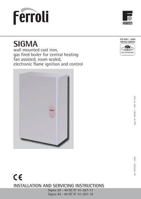
SIGMA<br />
<strong>wall</strong> <strong>mounted</strong> <strong>cast</strong> <strong>iron</strong>,<br />
<strong>gas</strong> fi red <strong>boiler</strong> <strong>for</strong> <strong>central</strong> <strong>heating</strong><br />
fan assisted, room sealed,<br />
electronic fl ame ig ni tion and control<br />
INSTALLATION AND SERVICING INSTRUCTIONS<br />
Sigma 20 - 40 GC N° 41-267-17<br />
Sigma 40 - 60 GC N° 41-267-18<br />
cod. 3543556/3 - 04/05 Appr. Nr. B 98.06 A - 0461 AT 0344
INDEX PAGE<br />
1. TECHNICAL CHARACTERISTICS ......................................................................................3<br />
2. INSTALLATION ..................................................................................................................6<br />
3. COMMISSIONING AND TESTING ..................................................................................22<br />
4. ADJUSTMENT..................................................................................................................23<br />
5. GAS CONVERSION .........................................................................................................24<br />
6. MAINTENANCE AND CLEANING .................................................................................25<br />
7. REPLACEMENT OF PARTS..............................................................................................27<br />
8. FAULT FINDING ..............................................................................................................30<br />
9. USER INSTRUCTIONS......................................................................................................33<br />
BENCHMARK...................................................................................................................34<br />
<br />
IMPORTANT<br />
Sigma<br />
Your "benchmark" Installation, Commissioning and Service Record Log Book is enclosed in the last pages<br />
of this manual. This record must be completed and left with the end user.<br />
<strong>Ferroli</strong> is a member of the Benchmark initiative and fully supports the aims of the programme. Benchmark<br />
has been introduced to improve the standards of installation and commissioning of <strong>central</strong> <strong>heating</strong><br />
systems in the UK and to encourage the regular servicing of all <strong>central</strong> <strong>heating</strong> systems to ensure<br />
safety and efficiency.<br />
CE MARK<br />
CE mark documents that the <strong>Ferroli</strong> <strong>gas</strong> appliances comply with the requirement contained in European<br />
directives applicable to them.<br />
In particular, the appliances comply with the following CEE directives and the technical specifications<br />
provided from them:<br />
• Gas appliances directive 90/396<br />
• Efficiencies directive 92/42<br />
• Low tension directive 73/23 (modified from the 93/68)<br />
• Electromagnetic compatibility directive 89/396 (modified from the 93/68)<br />
C.O.S.H.H.<br />
Materials used in the manufacture of this appliance are non hazardous and no special precautions are<br />
required when servicing.
Sigma<br />
1. TECHNICAL CHARACTERISTICS<br />
1.01 Introduction<br />
The Sigma is defined as a “room sealed” <strong>boiler</strong>, all air required <strong>for</strong> combustion is taken from outside the room in which it<br />
is installed. It is a new high per<strong>for</strong>mance <strong>gas</strong> <strong>fired</strong> heat generator, which is designed to provide indirect hot water and/or<br />
<strong>central</strong> <strong>heating</strong>. The <strong>cast</strong> <strong>iron</strong> heat exchanger is suitable <strong>for</strong> use on fully pumped hot water/<strong>central</strong> <strong>heating</strong> systems,<br />
which may be sealed or open vented. A special feature of this <strong>boiler</strong> is its built-in electronic flame ignition and control<br />
unit making burner operation completely automatic and safe.<br />
The main components are as follows:<br />
Cast <strong>iron</strong> heat exchanger specifically shaped <strong>for</strong> high efficiency.<br />
Ceramic fibre insulated combustion chamber<br />
One stainless steel bladed burner specifically designed <strong>for</strong> this <strong>boiler</strong>.<br />
Fan <strong>for</strong> discharge of combustion products and intake of combustion air.<br />
Differential air pressure switch. For safety reasons, this ensures the burner ignites only when the fan is<br />
functioning correctly.<br />
Hermetically sealed compartment made from corrosion-resistant steel enclosing the above components.<br />
Combination <strong>gas</strong> safety valve, complete with pressure stabiliser.<br />
Central <strong>heating</strong> flow temperature adjustment thermostat.<br />
Overheat safety thermostat.<br />
Electronic control unit <strong>for</strong> automatic flame ignition and control.<br />
Front view<br />
Central <strong>heating</strong> flow temperature sensor.<br />
A<br />
1.02 Dimension<br />
Right side view<br />
B 85 132<br />
Key<br />
1 - Ø 22 mm flow outlet<br />
2 - Ø 22 mm return inlet<br />
3 - Ø 15 <strong>gas</strong> inlet<br />
4 - Rear air inlet/flue outlet<br />
5 - Top air inlet/Flue outlet<br />
Model<br />
Sigma 20-40<br />
Sigma 40-60<br />
A<br />
mm<br />
320<br />
400<br />
B<br />
mm<br />
53<br />
133<br />
C<br />
mm<br />
35<br />
30<br />
600<br />
D<br />
mm<br />
60<br />
55<br />
120 50<br />
1<br />
3<br />
50<br />
50<br />
2<br />
15<br />
Fig. 1<br />
620<br />
147<br />
78<br />
25<br />
5<br />
25<br />
Top view<br />
200<br />
200<br />
4<br />
D<br />
<br />
C<br />
220
1.03 Technical data<br />
<br />
Model<br />
Sigma 20/40<br />
Sigma 40/60<br />
Model<br />
Sigma 20/40<br />
Sigma 40/60<br />
Model<br />
Sigma 20/40<br />
Sigma 40/60<br />
Flow<br />
1<br />
Ø<br />
22<br />
22<br />
Heat<br />
output<br />
Max<br />
kW<br />
11,7<br />
17,6<br />
G20-NG<br />
mbar<br />
20<br />
20<br />
Min<br />
kW<br />
5,5<br />
11,4<br />
Gas supply pressures<br />
IP 40<br />
IP 40<br />
Sigma<br />
Connections Max. working<br />
Boiler<br />
Protection Weight water<br />
Gas valve<br />
pressure<br />
C.H.circuit level<br />
contents<br />
Ø 1/2”<br />
Honeywell<br />
Return<br />
2<br />
Ø<br />
22<br />
22<br />
Max<br />
kW<br />
13,0<br />
19,5<br />
Heat<br />
input<br />
(net)<br />
G31-LPG<br />
mbar<br />
37<br />
37<br />
Gas inlet<br />
3<br />
Ø<br />
15<br />
15<br />
Min<br />
kW<br />
6,1<br />
12,7<br />
Max<br />
kW<br />
14,4<br />
21,7<br />
Heat<br />
input<br />
(gross)<br />
bar<br />
3<br />
3<br />
Min<br />
kW<br />
6,8<br />
14,1<br />
Minimum<br />
mbar<br />
3,1<br />
6,4<br />
G20-NG<br />
Ø<br />
3,0<br />
3,60<br />
G20-NG<br />
Injectors<br />
(mm)<br />
Burner <strong>gas</strong> pressures<br />
Nominal<br />
mbar<br />
14,0<br />
15,3<br />
G31-LPG<br />
Ø<br />
1,8<br />
2,30<br />
N.B. • Maximum working temperature 82°C, adjustable between 60°C and 82°C.<br />
kg<br />
30<br />
35<br />
Max<br />
1,37<br />
2,06<br />
Minimum<br />
mbar<br />
9,0<br />
16,0<br />
Gas flow rates<br />
G20 m 3 /h-NG G31 kg/h-LPG<br />
litres<br />
1,3<br />
1,6<br />
Min<br />
0,64<br />
1,34<br />
G31-LPG<br />
Max<br />
1,02<br />
1,53<br />
Nominal<br />
mbar<br />
36<br />
36<br />
Min<br />
0,48<br />
0,99<br />
VK 4105 A<br />
VK 4105 A
Sigma<br />
1.04 General Layout and Main Components<br />
5<br />
90<br />
28<br />
132<br />
27<br />
19<br />
1 91 16 1<br />
1.05 Boiler water fl ow diagram<br />
Pressure drop mm wg<br />
1 = Sigma 20-40<br />
2 = Sigma 40-60<br />
300<br />
200<br />
100<br />
90<br />
80<br />
70<br />
60<br />
50<br />
40<br />
30<br />
20<br />
10<br />
22 21 7<br />
Pressure loss diagram<br />
.1 .2<br />
10<br />
43<br />
49<br />
34<br />
11<br />
86<br />
121<br />
68<br />
63<br />
24<br />
83<br />
44<br />
151<br />
Fig. 2<br />
Fig. 3<br />
Key<br />
.3 .4 .5 .6 .7 .8 .9 1<br />
2 3<br />
Water flow rate (m 3 /h)<br />
1<br />
2<br />
1 Fixing points<br />
5 Room sealed compartment<br />
7 Inlet <strong>gas</strong>-cock<br />
10 Central <strong>heating</strong> flow outlet<br />
11 Central <strong>heating</strong> return inlet<br />
16 Fan<br />
19 Combustion chamber<br />
21 Gas injector<br />
22 Burner<br />
24 Spark and sensor electrode<br />
27 Cast <strong>iron</strong> heat exchanger<br />
28 Flue collector from heat exchanger<br />
34 Central <strong>heating</strong> flow<br />
temperature sensor<br />
43 Air pressure switch<br />
44 Gas valve<br />
49 Safety overheat thermostat<br />
63 Central <strong>heating</strong> temperature setting<br />
68 Control box with P.C.B.<br />
83 Full sequence automatic control<br />
86 Automatic control reset switch<br />
90 Flue outlet pressure test point<br />
91 Air pressure test point<br />
121 Boiler shut-down warning<br />
132 Flue <strong>gas</strong> deflector<br />
151 Drain tap<br />
Air in<br />
Flue out<br />
C.H.<br />
out<br />
Gas in<br />
<br />
C.H.<br />
in
2. INSTALLATION<br />
2.01 Important notices<br />
<br />
Sigma<br />
Assembly, installation, first start up and maintenance must be carried out by competent persons only, in accordance<br />
with all current technical regulations and directives.<br />
Gas Safety (Installation & Use) Regulations: 1996<br />
In the interest of safety, it is the law that all <strong>gas</strong> appliances are installed by a competent person in accordance with the<br />
above Regulations, Building Regulations/Building Standards Scotland, Codes of Practice, current I.E.E. Regulations and<br />
the byelaws of the Local Water Undertaking. Failure to comply with the Regulations may lead to prosecution; it is your<br />
responsibility to ensure that the law is complied with.<br />
This appliance must be installed strictly in accordance with these instructions and regulations:<br />
The Gas Safety Regulations (Installations & Use) 1996.<br />
The Local Building Regulations.<br />
The Building Regulations.<br />
The Buildings Standards (Scotland - Consolidated) Regulations.<br />
British Standards Codes of Practice:<br />
B.S. 5440 Part 1 2000 Flues<br />
B.S. 5440 Part 2 1989 Air supply<br />
B.S. 5449 1990 FORCED CIRCULATION HOT WATER SYSTEMS<br />
B.S. 6798 1987 INSTALLATION OF GAS FIRED HOT WATER BOILERS<br />
B.S. 6891 1989 GAS INSTALLATIONS<br />
B.S. 7671 1992 IEE WIRING REGULATIONS<br />
B.S. 4814 1990 SPECIFICATION FOR EXPANSION VESSELS<br />
B.S. 5482 1994 INSTALLATION OF LPG<br />
B.S. 7593 1992 TREATMENT OF WATER IN DOMESTIC HOT WATER CENTRAL HEATING SYSTEMS<br />
Model Water Bye Laws<br />
For Northern Ireland the rules in <strong>for</strong>ce apply<br />
N.B. For Northern Ireland the rules in <strong>for</strong>ce apply.<br />
Important - If the <strong>boiler</strong> is to be fitted in a timber framed building it should be fitted in accordance with<br />
the institute of <strong>gas</strong> engineers publication IGE/UP/1. If in doubt advice should be sought from the Local Gas<br />
Region of British Gas Plc.<br />
2.01.01 Location of Boiler<br />
The installation of the Sigma must be on a suitable non-combustible load bearing <strong>wall</strong> which will provide an adequate fixing<br />
<strong>for</strong> the <strong>boiler</strong> mounting bracket assembly. The location should be in an area where the water pipes will not be subjected<br />
to frost conditions. In siting the <strong>boiler</strong> the following limitations must be observed:<br />
The <strong>boiler</strong> may be installed in any room or internal space, although particular attention is drawn to the requirements of the<br />
current I.E.E. wiring regulations and in Scotland the electrical provisions of the building regulations applicable in Scotland,<br />
with respect to the installation of the <strong>boiler</strong> in a room or internal space containing a bath or shower.<br />
Where a room sealed appliance is installed in a room containing a bath or shower any electrical switch or<br />
appliance control utilising mains electricity must be situated so that it cannot be touched by a person using<br />
the bath or shower.<br />
2.01.02 Air Supply<br />
The room or compartment in which the <strong>boiler</strong> is installed does not require a purpose provided vent when using<br />
the standard concentric flue.<br />
2.01.03 Flue System<br />
The <strong>boiler</strong> allows the flue outlet to be taken from the rear of the <strong>boiler</strong>, from either side or vertically.<br />
It is absolutely essential, to ensure that products of combustion discharging from the terminal cannot re-enter<br />
the building, or enter any adjacent building, through ventilations, windows, doors, natural air infiltration or<br />
<strong>for</strong>ced ventilation/air conditioning.
Sigma<br />
2.01.04 Gas Supply<br />
If necessary the local Gas supplier should be consulted, at the installation planning stage, in order to establish<br />
the availability of an adequate supply of <strong>gas</strong>.<br />
An existing service pipe must not be used without prior consultation with the Local Gas supplier.<br />
A <strong>gas</strong> meter can only be connected by the Local Gas supplier, or by a Local Gas suppliers Contractor.<br />
Installation pipes should be fitted in accordance with BS6891-1988.<br />
Appliance inlet working pressure must be 20mbar MINIMUM (Natural <strong>gas</strong> - G20) or 37 mbar MINIMUM (LPG - G31).<br />
Pipework from the meter to the combination <strong>boiler</strong> must be of an adequate size.<br />
Do not use pipes of a smaller size than the combination <strong>boiler</strong> inlet <strong>gas</strong>cock connection.<br />
The complete installation must be tested <strong>for</strong> <strong>gas</strong> soundness and purged as described in BS6981-1988. All pipework<br />
must be adequately supported.<br />
2.02 Water System (sealed systems)<br />
Central <strong>heating</strong><br />
Detailed recommendations are given in BS6798, BS5449, BS6700 and CP342 Part 2. Pipework not <strong>for</strong>ming part of the<br />
useful <strong>heating</strong> suface should be insulated to prevent any heat losses or possible freezing (i.e. in roof spaces or ventilated<br />
underfloor spaces). Drain taps should be positioned at the lowest point of the system in accessible locations to permit<br />
the whole system to be drained down. The drain taps should be in accordance with BS2879. Copper tubing to BS2871,<br />
Part 1 is recommended <strong>for</strong> water carrying pipework. Pipework in horizontal runs should have a gradient where possible<br />
to facilitate the removal of air. Ensure that the <strong>boiler</strong> heat exchanger is not a natural point <strong>for</strong> air collection. A<br />
typical sealed <strong>heating</strong> system illustrated in fig. 4.<br />
Typical sealed fully pumped <strong>heating</strong> system<br />
Gas<br />
Pump<br />
1<br />
2<br />
Expansion<br />
vessel<br />
Fig. 4a<br />
3<br />
Filling point<br />
Cold water<br />
Note: A bypass must be fitted as far<br />
as possible from the <strong>boiler</strong> if<br />
thermostatic radiator valves<br />
are fitted thoughout.
Schematic layout <strong>for</strong> gravity DHW and pumped CH <strong>for</strong> Sigma Boiler<br />
Static Head<br />
<br />
min. 1 m<br />
15 mm<br />
22 mm<br />
Flow<br />
Open<br />
Vent<br />
Motorised valve<br />
28 mm<br />
gravity DHW<br />
28 mm<br />
Return<br />
28 mm<br />
Open<br />
Vent<br />
max. 150 mm<br />
Isolating valve<br />
CH Pump<br />
Fig. 4b<br />
By-pass<br />
To DHW taps<br />
Isolating valve<br />
Drain<br />
Sigma<br />
Motorised valve<br />
22 mm CH Radiator Radiator
Sigma<br />
Important - If thermostatic radiator valves are fitted throughout a bypass must be fitted to ensure a minimum flow rate<br />
through the <strong>boiler</strong> of 6 l/min. The bypass should be fitted as far as possible from the <strong>boiler</strong>.<br />
2.02.01 Safety valve<br />
A safety valve complying with the requirements of BS 6750 Part 1 must be fitted close to the <strong>boiler</strong> on the flow pipe by<br />
means of a horizontal or vertically upward connection with no intervening valve or restrictions and should be positioned<br />
to facilitate testing. The valve should be pre-set and nonadjustable to operate at a pressure of 3 bar (45 Ibf/in2 ). It must be<br />
arranged to discharge any water or steam through a pipe to a safe outlet position.<br />
2.02.02 Pressure gauge<br />
A pressure gauge of minimum range 0-4 bar (0-60 Ibf/in2) with a fill pressure indicator must be fitted to the system,<br />
preferably at the same point as the expansion vessel in an easily visible position.<br />
2.02.03 Venting<br />
A method of venting the system during filling and commissioning must be provided by fitting automatic air<br />
vents or by venting manually.<br />
2.02.04 Expansion vessel<br />
In a sealed system an expansion vessel complying with the requirements of BS 4814 must be fitted to the system<br />
by means of a connection close to the inlet side of the circulating pump in accordance with the manufacturers<br />
instructions, the connecting pipe being unrestricted and not less than 15 mm (1/2 in) nominal size. The volume<br />
of the vessel should be suitable <strong>for</strong> the system water content and the nitrogen or air charge pressure should<br />
not be less than the system static head.<br />
Further details of sealed system design can be obtained from BS 5449: Part 1 and the British Gas publication entitled<br />
Specifications <strong>for</strong> Domestic Wet Central Heating Systems.<br />
2.02.05 Water treatment<br />
If water treatment is used ferroli limited recommend only the<br />
use of Fernox or Sentinel water treatment products, which must<br />
be used in accordance with the manufacturers instructions. For<br />
further in<strong>for</strong>mation contact:<br />
Fernox Manufacturing Co. LTD. Sentinel Division<br />
Tandern house, Marlowe Way Betz Dearborn LTD<br />
Croydon, surrey, CRO 4YS Widnes, Cheshire WA8 8ND<br />
Tel: 0870 5601 5000 Tel: 0151 424 5351<br />
Note - If the <strong>boiler</strong> is installed in an existing system any<br />
unsuitable additives must be removed by thorough cleansing.<br />
All systems should be cleansed according to B.S. 7593.<br />
Note - In hard water areas treatment to prevent lime scale<br />
may be necessary.<br />
Note - It is important that the correct concentration of the<br />
water treatment product is maintained in accordance with the manufacturers instructions.<br />
2.03 Gas connection<br />
VESSEL CHARGE<br />
PRESSURE (bar)<br />
INITIAL SYSTEM<br />
PRESSURE (bar)<br />
TOTAL WATER<br />
CONTENT of SYSTEM<br />
Litres<br />
25<br />
50<br />
75<br />
100<br />
125<br />
150<br />
175<br />
200<br />
For syst. volumes other than<br />
those given above, mult. the syst.<br />
volume by the factor across.<br />
Sizing of expansion vessels:<br />
Gas connection must be carried out using a rigid pipe.<br />
The flow at the <strong>gas</strong> meter should be sufficient <strong>for</strong> the simultaneous use of all appliances connected to it. Connect<br />
the <strong>gas</strong> supply to the <strong>boiler</strong> according to current regulations. The diameter of the <strong>gas</strong> cock leaving the <strong>boiler</strong> is not<br />
the determining factor in choosing the diameter of the pipe between the appliance and the meter. This must be<br />
selected in relation to length and pressure drop.<br />
The whole of the <strong>gas</strong> installation including the meter should be inspected and tested <strong>for</strong> soundness and purged<br />
in accordance with BS6891-1988.<br />
1.0<br />
3.5<br />
7.0<br />
10.5<br />
14.0<br />
17.5<br />
21.0<br />
24.5<br />
28.0<br />
0.140<br />
0.5 1.0<br />
1.5<br />
2.0<br />
1.5<br />
2.0<br />
EXPANSION VESSEL VOLUME (litres)<br />
6.5<br />
12.9<br />
19.4<br />
25.9<br />
32.4<br />
38.8<br />
45.3<br />
51.8<br />
0.259<br />
2.0<br />
13.7<br />
27.5<br />
41.3<br />
55.1<br />
68.9<br />
82.6<br />
96.4<br />
110.2<br />
0.551<br />
1.5<br />
4.7<br />
9.5<br />
14.2<br />
19.0<br />
23.7<br />
28.5<br />
33.2<br />
38.0<br />
0.190<br />
10.3<br />
20.6<br />
30.9<br />
41.2<br />
51.5<br />
61.8<br />
72.1<br />
82.4<br />
0.412<br />
8.3<br />
16.5<br />
24.8<br />
33.1<br />
41.3<br />
49.6<br />
57.9<br />
66.2<br />
0.33
2.04 Wall Mounting<br />
2.04.01 Drilling Template<br />
<br />
Model<br />
Sigma 20-40<br />
Sigma 40-60<br />
Ø118<br />
80<br />
B<br />
C<br />
200 min.<br />
111<br />
A<br />
320<br />
400<br />
135<br />
A<br />
B<br />
60 min.<br />
140 min.<br />
WARNING:<br />
C.H. connection<br />
on this side<br />
C<br />
120<br />
200<br />
Fig. 5<br />
Fig. 6a Fig. 6b<br />
230 min.<br />
620<br />
200 min<br />
810 min<br />
200 min 610<br />
Ø90<br />
Ø90<br />
147<br />
80<br />
100<br />
Boiler<br />
mounting<br />
plate<br />
B<br />
C<br />
200 min.<br />
165 min.<br />
91<br />
A<br />
100<br />
Ø*<br />
200<br />
205 min<br />
135<br />
A<br />
105 min<br />
254,5<br />
620<br />
5 min<br />
WARNING:<br />
C.H. connection<br />
on this side<br />
350 min.<br />
620<br />
Sigma<br />
Minimum clearances and drilling template <strong>for</strong> standard<br />
rear flue.<br />
Drilling template <strong>for</strong> orizontal concentric flue. Drilling template <strong>for</strong> two pipe system with orizontal<br />
air inlet.
Sigma<br />
2.04.02 Wall mounting instructions <strong>for</strong> Rear Flue Application<br />
1<br />
Fig. 7<br />
Select suitable mounting position <strong>for</strong><br />
<strong>boiler</strong>. Refer to fig. 6 <strong>for</strong> dimensions and<br />
minimum clearance. Using the template<br />
or mounting plate mark flue outlet and<br />
<strong>boiler</strong> mounting points.<br />
2<br />
Fig. 8<br />
Drill four 10 mm holes 70 mm deep to<br />
accept the <strong>wall</strong> plug. Using a core drill<br />
cut hole <strong>for</strong> the flue.<br />
Drill cut a 118 mm diameter hole if it<br />
is possible insert the flue-pipe from<br />
outside of the room; drill cut a 127 mm<br />
diameter hole if to insert the flue-pipe<br />
from inside of the room.<br />
4a 4b<br />
5a 5b<br />
3<br />
Fig. 9<br />
Insert the plastic plugs.<br />
Ø 127<br />
Fig. 10a Fig. 10b<br />
Insert flue-pipe from inside of the room (core drill 127 mm hole)...<br />
Ø 118<br />
Fig. 11a Fig. 11b<br />
... or insert flue-pipe from outside of the room (core drill 118 mm hole).
6 7<br />
Fig. 12 Fig. 13<br />
Gently pull back until <strong>wall</strong> seal is flush with the <strong>wall</strong>.<br />
8<br />
Fig. 14 Fig. 15<br />
Through plate into air tube, drill two holes and fix in place<br />
using two self tapping screws n° 6 x 6mm long.<br />
10<br />
Fig. 16 Fig. 17<br />
Insert the aluminium flue pipe into white plastic outer flue,<br />
making sure the aluminium pipe sits fully and <strong>central</strong>ly<br />
into the flue terminal.<br />
<br />
9<br />
11<br />
15 mm<br />
Sigma<br />
Position the <strong>wall</strong> plate on the <strong>wall</strong>. Fix plate to <strong>wall</strong> with the<br />
square <strong>gas</strong>ket between the <strong>wall</strong> and the plate use the large<br />
diameter washers <strong>for</strong> the bolts ad screws.<br />
Cut the outer flue flush with the flange on the hanging<br />
plate.<br />
Mark the aluminium flue pipe at the point it is flush with<br />
the mounting plate. Add 15 mm to this mark and cut the<br />
aluminium inner flue pipe at this point.
Sigma<br />
12 13 14<br />
Fig. 18 Fig. 19 Fig. 20<br />
Install the inner metal flue "a" into the<br />
adapter "b".<br />
2.05 Top outlet fl u e conversion<br />
1<br />
Fig. 21a<br />
Remove fan by pulling off electrical connections. Pull off air<br />
pressure switch tubes from the air pressure switch. Remove<br />
the two screws "b" and rotate the fan upward to disengage<br />
it from the securing pin "a".<br />
3<br />
Fig. 22a<br />
Take off the four screws which fix the top sealed chamber<br />
cover, remove the cover and <strong>gas</strong>ket.<br />
Lift <strong>boiler</strong> with flue pipe in place,<br />
engage inner and outer flue, slide into<br />
position.<br />
2<br />
Fig. 21b<br />
4<br />
Fig. 22b<br />
Make sure the inner flue is fully engage<br />
in the flue terminal, secure <strong>boiler</strong> with<br />
two nuts and washers "a" and "b".<br />
Rotate the fan upward to disengage it from the securing<br />
pin "a". Remove the securing screw that locates the<br />
fan nozzle extension to the fan and remove the nozzle<br />
extension.<br />
Rotate the cover and <strong>gas</strong>ket through 90° and fit it to<br />
the rear of the <strong>boiler</strong> to cover the original flue outlet.<br />
Secure them both in place with the four screws removed
5<br />
c<br />
6<br />
Fig. 23<br />
10<br />
Fig. 28<br />
Fix the restrictor with the two screws<br />
"a" inside the pipe connection "b".<br />
<br />
d<br />
c-<br />
d<br />
Common<br />
For top outlet<br />
For rear outlet<br />
Remove fan mounting plate by undoing<br />
the three fixing screws "c".<br />
11<br />
b<br />
b<br />
Fig. 29<br />
a<br />
9<br />
Fig. 27<br />
Insert the correct restrictor.<br />
(See section 2.07).<br />
Sigma<br />
Boiler is fitted as standard with Ø36 (Sigma 20-40) or Ø41 (Sigma 40-60) restrictor. Identify on 2.07 the correct restrictor <strong>for</strong><br />
your flue system. If it is necessary to change it. follow instructions at step 7-10, if not, go to step 11.<br />
7 8<br />
Remove the two screws "a" from pipe<br />
connection "b".<br />
c<br />
d<br />
For rear<br />
outlet<br />
Fig. 24<br />
Fig. 25 Fig. 26<br />
Remove restrictor "c".<br />
For top<br />
outlet<br />
Rotate the fan through 90° so that the fan nozzle points upward. Secure the fan<br />
to the plate in the new position using screws in position "d".<br />
Refit wiring connections to fan and air<br />
pressure switch tubes ensuring correct<br />
orientation. I.E. red tube to air pressure<br />
switch connection with red dot (+)<br />
and clear tube to air pressure switch<br />
connection with no paint marking (-).<br />
Fit the fan into the <strong>boiler</strong> rotating<br />
the front upwards to engage with the<br />
pin "a".<br />
Secure with the screws "b".
Sigma<br />
2.06 Top outlet Flue Connection<br />
Three different connection are available from top of the <strong>boiler</strong>, using accessories as reported on fig. 30a, b e c and<br />
on examples a next page.<br />
1 Top outlet horizontal 2 Top outlet two 3<br />
2.06.01 Examples of top fl ue connection<br />
1 Example of concentric flue Ø 100<br />
with appliance bend use<br />
Fig. 31<br />
Note • Bear in mind that the two concentric<br />
pipes must slope downwards away from the<br />
<strong>boiler</strong> at a rate of about 3 mm/m to avoid<br />
rainwater entering the <strong>boiler</strong>. Outside, the<br />
pipes should protrude from the <strong>wall</strong> between<br />
10 and 60 mm.<br />
Warning • Back exit with coaxial bend is<br />
not possible<br />
concentric fl ue<br />
Vertical Connection, concentric bend<br />
and two pipe separator can be<br />
supplied on request.<br />
2 Example of direct roof flue outlet<br />
and <strong>wall</strong> air inlet with 2 pipe system<br />
Fig. 32<br />
pipe system<br />
Fig. 30a Fig. 30b Fig. 30c<br />
Warning • Back exit with Air/Flue T separator<br />
is not possible<br />
Top outlet vertical<br />
concentric fl ue<br />
3 Example of concentric flue Ø 100<br />
with vertical outlet flue use.<br />
Fig. 33<br />
Fig. 30
2.07 Restrictor and max fl ue length<br />
2.07.01 Concentric Flue System<br />
First table below shows the maximum flue lengths available <strong>for</strong> <strong>boiler</strong>s with concentric systems.<br />
For correct calculation remember to include the reduction <strong>for</strong> bend and flue terminals listed on second table.<br />
Maximum flue<br />
length permissible<br />
Sigma 20/40<br />
Sigma 40/60<br />
<br />
100 mm concentric<br />
Vertical *Horizontal<br />
125 mm concentric<br />
Vertical *Horizontal<br />
100 mm<br />
concentric<br />
back exit<br />
4 m 3 m 5 m 5 m 1 m<br />
* For horizontal flueing the reduction <strong>for</strong> appliance bend are already included.<br />
A<br />
B<br />
C<br />
Sigma<br />
20-40<br />
Sigma<br />
40-60<br />
Reduction <strong>for</strong> bend<br />
100 mm concentric bend 90°<br />
100 mm concentric bend 45°<br />
125 mm concentric bend 90°<br />
125 mm concentric bend 45°<br />
A Horizontal concentric B Back concentric C Vertical concentric<br />
L (max. 3 m.)<br />
Fig. 34 Fig. 35<br />
Restrictor pipe<br />
configuration<br />
L 1m<br />
1m L 3m<br />
L 1m<br />
L 2m<br />
L 2m<br />
Ø36<br />
Ø39<br />
Ø36<br />
Ø36<br />
Ø39<br />
Ø41<br />
Ø46<br />
Ø46<br />
Ø41<br />
Ø46<br />
L (max. 1 m.)<br />
To calculate the restrictor, identify your flue pipe configuration (A, B or C) and<br />
choose the correct restrictor diameter from the restrictor table below.<br />
Boiler is fitted as standard with Ø36 and Ø46 restrictor.<br />
For instruction on changing restrictor refer to step 7-10 at pages 14.<br />
L (max. 4 m.)<br />
Fig. 36<br />
Sigma<br />
1 m<br />
0,5 m<br />
0,5 m<br />
0,25 m
Sigma<br />
2.07.02 Two pipe fl ue system<br />
1. Utilise the pipes and fittings flows resistance tables on the following pages and calculate the total flow resistance in<br />
metres-air, by adding the flow resistances of the components in the whole air-flue system, based on their position<br />
(vertical or horizontal, air inlet or flue outlet).<br />
Please note that the same fitting, identified by a one code (i.e. 1 pipe diameter 80, code KWMA83A), can offer<br />
different flow resistances if positioned as air inlet or flue outlet, if placed vertically or horizontally.<br />
The fl ow resistance of the special two pipe fl ue-air adapters do not have to be included in the calculation as<br />
they are already included in the maximum length calculation.<br />
IMPORTANT: the pipes and fittings flow resistance (reduction) have been summarised on the following page. The<br />
fl ow resistance values written refer only to <strong>Ferroli</strong> pipes and fi ttings.<br />
2. Verify that the total flow resistance calculated is less or equal to 40 metre.<br />
3. Choose the more suitable restrictor from table below.<br />
Tab. 5<br />
Ref.<br />
1<br />
2<br />
3<br />
4<br />
5<br />
6<br />
7<br />
Description<br />
Tab. 3<br />
Connection <strong>for</strong> concentric pipe cod. KWMR52A<br />
Air/Flue T separator cod. KWMA90U<br />
Male - Female flue Ø 80 mm<br />
Air<br />
Flue bend 80 mm<br />
Air <strong>wall</strong> terminal outlet flue Ø80<br />
Air <strong>wall</strong> terminal air Ø80<br />
Flue<br />
Total fl ow resistance 17,5 m:<br />
use restrictor Ø41<br />
Total flow resistance<br />
0 - 20 metres<br />
20 - 30 metres<br />
30 - 40 metres<br />
Horizontal<br />
Vertical<br />
Horizontal<br />
Vertical<br />
N° of<br />
pieces<br />
1<br />
1<br />
1<br />
/<br />
1<br />
5<br />
1<br />
1<br />
1<br />
Total<br />
Length<br />
reduction<br />
/<br />
already included<br />
1<br />
/<br />
2<br />
5<br />
2,5<br />
5<br />
2<br />
17,5<br />
Sigma 20/40<br />
Example of calculation <strong>for</strong> <strong>wall</strong> inlet/outlet with 2 pipe system maximum total fl ue length: 40 metres<br />
Fig. 37<br />
Ø36<br />
Ø39<br />
Ø39<br />
Use restrictor:<br />
7<br />
6<br />
Sigma 40/60<br />
Ø41<br />
Ø46<br />
Ø46<br />
4<br />
1 m<br />
3<br />
Sigma 60<br />
4<br />
2<br />
5 m<br />
<br />
5<br />
1
Pipe and fi ttings reduction table (shown in Metres)<br />
<br />
Sigma
Sigma<br />
2.07.03 Terminal Position<br />
Dimensions Terminal position<br />
(kW input expressed in net)<br />
Aa Directly below an opening, air brick, (0-7 kW)<br />
300 mm 300 mm Not allowed 300 mm<br />
opening windows, etc. (>7-14 kW)<br />
600 mm<br />
(>14-32 kW)<br />
1500 mm<br />
(>32-70 kW)<br />
2000 mm<br />
Ba Above an opening, air brick, (0-7 kW)<br />
300 mm 300 mm Not allowed 300 mm<br />
opening windows, etc. (>7-14 kW)<br />
300 mm<br />
(>14-32 kW)<br />
300 mm<br />
(>32-70 kW)<br />
600 mm<br />
Ca Horizontally to an opening, air brick, (0-7 kW)<br />
300 mm 300 mm Not allowed 300 mm<br />
opening windows, etc. (>7-14 kW)<br />
400 mm<br />
(>14-32 kW)<br />
600 mm<br />
(>32-70 kW)<br />
600 mm<br />
D Below gutters, soil pipes or drain pipes<br />
300 mm 75 mm Not allowed 75 mm<br />
E Below eaves<br />
300 mm 200 mm Not allowed 200 mm<br />
F Below balconies or car port roof<br />
600 mm 200 mm Not allowed 200 mm<br />
G From a vertical drain pipe or soil pipe<br />
300 mm 150 mmb Not allowed 150 mm<br />
H From an internal or external corner<br />
600 mm 300 mm Not allowed 200 mm<br />
I Above ground roof or balcony level<br />
300 mm 300 mm Not allowed 300 mm<br />
J From a surface facing the terminal<br />
(also see 6.1.2)<br />
600 mm 600 mm N/A 600 mm<br />
K From a terminal facing the terminal<br />
600 mm 1200 mm N/A 1200 mm<br />
L From an opening in the car port ( e.g. door,<br />
window) into the dwelling<br />
1200 mm 1200 mm N/A 1200 mm<br />
M Vertically from a terminal on the same <strong>wall</strong><br />
1500 mm 1500 mm N/A 1500 mm<br />
N Horizontally from a terminal on the same <strong>wall</strong><br />
300 mm 300 mm N/A 300 mm<br />
O From the <strong>wall</strong> on which the terminal is <strong>mounted</strong><br />
N/A N/A N/A 50 mm<br />
P From a vertical structure on the roof<br />
N/A N/A See Table 2<br />
and Fig. 6b<br />
N/A<br />
Q Above intersection with roof<br />
N/A N/A See Table 2<br />
and Fig. 4<br />
150 mm<br />
NOTE N/A = Not applicable<br />
2.08 Electrical connection<br />
The <strong>boiler</strong> must be connected to a single phase 230V 50Hz electricity supply with a 3 A max. fuse and a bipolar switch<br />
with contact opening of at least 3 mm fitted between the <strong>boiler</strong> and the electricity supply. The <strong>boiler</strong> must always be<br />
connected to an efficient earth installation. In the electrical box, there is a 3 pole terminal block <strong>for</strong> connecting the<br />
<strong>boiler</strong> to the mains (230V 50Hz) and a 3 pole block <strong>for</strong> connecting a<br />
circulating pump (not supplied). See Wiring diagram (fig. 41a) <strong>for</strong> the<br />
connection of external control.<br />
Temp. kOhm<br />
When the <strong>boiler</strong> is connected to an electricity main, it is essential TO<br />
ENSURE CORRECT POLARITY (LIVE: brown cable, NEUTRAL: blue<br />
cable, EARTH: yellow-green cable).<br />
25°C 1000 kOhm<br />
All wiring must con<strong>for</strong>m to current I.E.E. regulations.<br />
Note: If the power supply cable has to be replaced, use “0.75mm<br />
(24/0.20) cable only to BS6500 with a maximum external<br />
diameter of 8 mm.<br />
Key<br />
63. CH temperature setting<br />
86. Reset switch<br />
101. Main P.C.B.<br />
121. Boiler shut-down warning (Led)<br />
X3-X4-X5-X8. Connectors<br />
JP. Link<br />
J<br />
F<br />
l<br />
L<br />
Balanced flues room<br />
sealed<br />
Natural<br />
draught<br />
Fanned<br />
draught<br />
Natural<br />
draught<br />
Q<br />
G<br />
Open flues<br />
Fig. 39<br />
Q<br />
B C<br />
Fanned<br />
draught<br />
a In addition, the terminal should not be nearer than 150 mm (fanned draucht) or 300 mm (natural draught) to an opening in the building fabric <strong>for</strong>med <strong>for</strong> the purpose of accommodating<br />
a built-in element such as a window frame, (see Figure C2). Separation distances are linked to the rated heat inputs as shown.<br />
b This dimension may be reduced to 75 mm <strong>for</strong> appliances of up to 5 kW heat input.<br />
A<br />
P<br />
D, E<br />
H H<br />
Fig. 38<br />
Temp.<br />
sensor<br />
NTC 34<br />
101<br />
X3<br />
G C P<br />
X8<br />
JP<br />
M<br />
N<br />
M<br />
A approved terminal guard (part. No. C2) should be screwed<br />
to the <strong>wall</strong> <strong>central</strong>ly over the terminal, when the distance<br />
is less than 2 m from the outside floor.<br />
N<br />
60°C<br />
82°C<br />
Q<br />
X4 X5<br />
1 4 1 5<br />
63<br />
K<br />
185 kOhm<br />
80 kOhm<br />
121<br />
86
2.08.01 Schematic wiring diagram <strong>for</strong> fully pumped system<br />
<br />
72<br />
24<br />
230V ~<br />
50 Hz<br />
32<br />
SwL L N PL PN<br />
YG<br />
Blue<br />
YG<br />
Blue<br />
12 11 10<br />
BR<br />
V<br />
G<br />
W<br />
Blue<br />
BR<br />
BL<br />
Key<br />
16 Fan<br />
24 Spark and sensor electrode<br />
32 Central <strong>heating</strong> pump (not fitted)<br />
34 Central <strong>heating</strong> flow temperature sensor<br />
43 Air pressure switch<br />
49 Safety thermostat<br />
63 C.H. temperature adjustment<br />
72 External controls<br />
83 Full sequence automatic control on <strong>gas</strong> valve<br />
86 Reset switch<br />
101 Main P.C.B.<br />
121 Boiler shut-down warning (Led)<br />
9<br />
83<br />
8<br />
7<br />
6<br />
5<br />
4<br />
Blue<br />
Fig. 40a<br />
3<br />
34<br />
2<br />
1<br />
101<br />
X3<br />
43<br />
NO NC<br />
BL<br />
BL<br />
C<br />
G C P<br />
X8<br />
JP<br />
Fully<br />
pumped<br />
W<br />
R W<br />
Sigma<br />
X4 X5<br />
1 4 1 5<br />
Colors key<br />
BR Brown<br />
Blue Blue<br />
BL Black<br />
W White<br />
O Orange<br />
63<br />
49<br />
BR<br />
16<br />
O<br />
P<br />
121<br />
G Grey<br />
R Red<br />
V Violet<br />
P Pink<br />
YG Yellow-Green<br />
If there are no external<br />
controls fi tted, connect the<br />
SWL terminal to permanent<br />
live in the junction box<br />
Blue<br />
86
Sigma<br />
2.08.02 Schematic wiring diagram <strong>for</strong> fully pumped CH and gravity DHW<br />
24<br />
230V ~<br />
50 Hz<br />
SwL L N PL<br />
YG<br />
Blue<br />
from pump<br />
YG<br />
Blue<br />
12 11 10<br />
BR<br />
V<br />
G<br />
W<br />
Blue<br />
BR<br />
BL<br />
Key<br />
16 Fan<br />
24 Spark and sensor electrode<br />
34 Central <strong>heating</strong> flow temperature sensor<br />
43 Air pressure switch<br />
49 Safety thermostat<br />
63 C.H. temperature adjustment<br />
83 Full sequence automatic control on <strong>gas</strong> valve<br />
86 Reset switch<br />
101 Main P.C.B.<br />
121 Boiler shut-down warning (Led)<br />
9<br />
83<br />
If there are no external controls fi tted, connect<br />
the SWL terminal to permanent live in the<br />
junction box<br />
ATTENTION: In gravity system is necessary to<br />
move the jumper JP From CP to GC contact<br />
in 8X.<br />
8<br />
7<br />
6<br />
5<br />
4<br />
Blue<br />
3<br />
34<br />
Fig. 40b<br />
2<br />
1<br />
101<br />
X3<br />
43<br />
NO NC<br />
BL<br />
BL<br />
G C P<br />
C<br />
W<br />
R W<br />
X4 X5<br />
X8<br />
JP<br />
Gravity domestic<br />
hot water<br />
Colors key<br />
BR Brown<br />
Blue Blue<br />
BL Black<br />
W White<br />
O Orange<br />
1 4 1 5<br />
63<br />
49<br />
BR<br />
16<br />
O<br />
P<br />
121<br />
G Grey<br />
R Red<br />
V Violet<br />
P Pink<br />
YG Yellow-Green<br />
Blue<br />
86
3. COMMISSIONING AND TESTING<br />
3.01 Checks to be carried out be<strong>for</strong>e starting up <strong>for</strong> the fi rst time<br />
<br />
Sigma<br />
When firing the <strong>boiler</strong> up <strong>for</strong> the first time, it is good practice to check:<br />
that the isolation valves between the <strong>boiler</strong> and <strong>central</strong> <strong>heating</strong> systems are open;<br />
that the <strong>central</strong> <strong>heating</strong> system is well filled and vented;<br />
that there are no <strong>gas</strong> or water leaks from the <strong>central</strong> <strong>heating</strong> system or <strong>boiler</strong>;<br />
that the electric connections are correct and the earth wire of the <strong>boiler</strong> is connected to an efficient earthing<br />
installation;<br />
that there are no inflammable liquids or materials near the <strong>boiler</strong>;<br />
that the <strong>central</strong> <strong>heating</strong> <strong>gas</strong> pressure and flow rate are as required.<br />
3.02 Starting up the <strong>boiler</strong><br />
• Open the <strong>gas</strong> cock of the <strong>boiler</strong>.<br />
• Vent air present in the pipe upstream of the <strong>gas</strong> valve.<br />
• Turn on the switch (if present) or plug upstream of the <strong>boiler</strong>.<br />
• Rotate the C.H. temperature adjustment knob above Min position.<br />
• Set the room thermostat (if fitted) to maximum.<br />
• At this point, the burner ignites and the <strong>boiler</strong> starts to function automatically, controlled by its control<br />
and safety devices.<br />
Note - If after completing the start-up procedure correctly, the burner fails to ignite and the <strong>boiler</strong> shut down warning<br />
lights up, wait about 15 seconds then press the reset switch. The reset electronic control unit will repeat the start-up cycle.<br />
If after a second attempt the burners still fail to ignite, consult the paragraph “Troubleshooting”.<br />
Note - If there is a power failure while the <strong>boiler</strong> is in operation, the burners automatically go out and re-ignite<br />
when the power returns.<br />
WARNING<br />
If the system is filled with very cold water, the <strong>boiler</strong> will automatically light due to the frost thermostat sensing the low<br />
temperature. The <strong>boiler</strong> will not shut down, until the water temperature reaches 10°C.<br />
3.03 Shutting down<br />
To shut down the <strong>boiler</strong> <strong>for</strong> short periods<br />
• Set the temperature adjustment knob to "Off" position.<br />
To shut down the <strong>boiler</strong> <strong>for</strong> long periods<br />
• Turn off <strong>gas</strong> supply.<br />
• Turn off the electricity supply.<br />
IMPORTANT<br />
The <strong>boiler</strong> is protected by integral frost protection, but if the <strong>boiler</strong> is not to be used <strong>for</strong> a long period of<br />
time, the system should be drained.<br />
Note: The frost thermostat operates even if the temperature adjustment knob is in the OFF position and it is necessary<br />
there<strong>for</strong>e, if the system is drained, <strong>for</strong> the external electrical and <strong>gas</strong> supplies to be isolated.<br />
It is recommended that a label be affixed to the appliance to draw attention to the fact that the system<br />
has been drained.<br />
3.04 Checks and tests after fi rst start-up<br />
Check there are no leaks in the <strong>gas</strong> and water circuits.<br />
Check correct <strong>boiler</strong> start up by carrying out start up and shut down tests using the <strong>boiler</strong> stat.<br />
Check the integrity of the air-flue pipes during <strong>boiler</strong> operation.<br />
Check that the <strong>gas</strong> consumption indicated on the meter corresponds to that given in Technical Data (paragraph<br />
1.03).<br />
Check that water is circulating correct. Balance the radiators to ensure that the flow and return differential<br />
does not exceed 20°C.
Sigma<br />
4. ADJUSTMENT<br />
4.01 Adjusting the <strong>gas</strong> pressure and heat output<br />
The following adjustments must be carried out by qualified<br />
personnel only.<br />
To adjust <strong>boiler</strong> heat input simply adjust the burner<br />
pressure <strong>gas</strong> via the pressure regulator on the <strong>gas</strong> valve<br />
(fig. 41).<br />
Adjust the <strong>gas</strong> pressure at the burner by turning the pressure<br />
regulating screw: turn it clockwise to increase the burner<br />
pressure and anticlockwise to decrease it.<br />
The diagrams indicate the variation in heat output to<br />
the water as burner working pressure is varied (fig. 42a<br />
and 42b).<br />
Adjusting <strong>boiler</strong> output to the actual requirements of<br />
the <strong>central</strong> <strong>heating</strong> system will minimise <strong>boiler</strong> cycling<br />
thus saving fuel, varying the output has virtually no<br />
effect on the efficiency and combustion characteristics<br />
of the <strong>boiler</strong>.<br />
Note: with LPG (G31) the pressure regulating screw must be all the way in. Fig. 41<br />
mbar<br />
17<br />
16<br />
15<br />
14<br />
13<br />
12<br />
11<br />
10<br />
9<br />
8<br />
7<br />
6<br />
5<br />
4<br />
3<br />
4<br />
5<br />
Diagram of pressures and outputs<br />
with Natural <strong>gas</strong> (G20)<br />
6<br />
1<br />
7 8 9 10 11 12<br />
kW<br />
13 14 15 16 17 18 19 20<br />
Fig. 42a<br />
2<br />
mbar<br />
35<br />
30<br />
25<br />
20<br />
15<br />
10<br />
1 = Sigma 20-40<br />
2 = Sigma 40-60<br />
4<br />
5<br />
6<br />
Outlet<br />
pressure<br />
Test Point<br />
Inlet<br />
pressure<br />
Test Point<br />
Pressure regulator<br />
protection plug<br />
Diagram of pressures and outputs<br />
with LPG (G31)<br />
7<br />
8<br />
OUT<br />
I<br />
Inlet<br />
<strong>gas</strong>cock<br />
1<br />
9 10 11 12 13 14 15 16 17<br />
kW<br />
Fig. 42b<br />
2<br />
18 19 20
4.02 Adjusting <strong>central</strong> <strong>heating</strong> fl ow temperature<br />
<br />
Fig. 43<br />
Sigma<br />
Central <strong>heating</strong> water temperature is adjusted by rotating the control knob (fig. 52). Rotate the knob clockwise<br />
to increase water temperature, anticlockwise to reduce water temperature. Temperature can be varied from a<br />
minimum of 60°C to a maximum of 82°C.<br />
However, we recommend not operating the <strong>boiler</strong> below 50°C.<br />
4.03 Adjusting room temperature (when a room thermostat is fitted)<br />
Room temperature is controlled by positioning the room thermostat knob to the required value. The thermostat<br />
automatically controls the <strong>boiler</strong>, temporarily interrupting the electrical supply subject to the room heat<br />
requirements.<br />
4.04 Adjusting <strong>central</strong> <strong>heating</strong> system pressure<br />
The pressure of water in the <strong>central</strong> <strong>heating</strong> system is adjusted as described in the paragraph 2.02.07.<br />
N.B. - To avoid incurring unnecessary expense, in the event of <strong>boiler</strong> shut down, check that this is not caused by a lack of<br />
electricity or <strong>gas</strong>, or low water pressure be<strong>for</strong>e calling the Customer Technical Service Helpline.<br />
4.05 Determining combustion effi ciency and the composition of the fl ue <strong>gas</strong>es<br />
On the <strong>boiler</strong> there are two test points, one <strong>for</strong> flue <strong>gas</strong> and the other <strong>for</strong> air.<br />
To carry out the tests, proceed as follows:<br />
1) Open the air and flue <strong>gas</strong> test points;<br />
2) Introduce the probes;<br />
3) Switch ON the <strong>boiler</strong>;<br />
N.B. To ensure correct readings the <strong>boiler</strong> must have reached normal operating temperature. Testing the <strong>boiler</strong><br />
be<strong>for</strong>e thermal equilibrium has been attained will give incorrect readings.<br />
5. GAS CONVERSION<br />
The following adjustment and conversion operations must be carried out by qualified personnel. FERROLI Limited<br />
accepts no liability <strong>for</strong> damage to property or personal injury resulting from tampering with the <strong>boiler</strong> by<br />
unauthorised persons.<br />
To convert the <strong>boiler</strong> from Natural <strong>gas</strong> to LPG and vice<br />
versa, the burner injector must be replaced (see fig. 43).<br />
Gas valve<br />
Gas pressures must then be adjusted on the <strong>gas</strong> valve as<br />
described in the paragraph 4.01.<br />
Note: After converting the <strong>boiler</strong> from natural <strong>gas</strong> to<br />
liquid <strong>gas</strong>, fi t the orange plate in the conversion kit<br />
near the data plate.<br />
Note: injector diameters and pressures at the main<br />
burner are given in Technical Data (1.03).<br />
Injector<br />
Full sequence<br />
automatic control<br />
Gas cock
Sigma<br />
6. MAINTENANCE AND CLEANING<br />
The following operations must be carried out by Corgi registered engineers only.<br />
6.01 Annual Servicing<br />
The following should be checked at least once a year:<br />
Water pressure in the <strong>central</strong> <strong>heating</strong> system when cold should be<br />
about 1 bar. If this is not the case, bring it back to this value.<br />
Check control and safety devices (<strong>gas</strong> valve, thermostats, etc)<br />
are functioning correctly.<br />
The burner and heat exchanger must be clean. To avoid damage,<br />
always clean them with a soft brush or compressed air. Never<br />
use chemical products.<br />
The expansion vessel (if fitted) must be checked.<br />
Check there are no leaks in the <strong>gas</strong> and water circuits.<br />
Check the air-flue <strong>gas</strong> duct terminal is free from obstructions<br />
and sound.<br />
The electrode must be free from corrosion build up and correctly<br />
positioned (see fig. 44).<br />
Gas flow and pressure must correspond to the values given in the<br />
Technical Data (paragraph 1.03).<br />
The pump must be free to rotate.<br />
6.02 Cleaning the <strong>boiler</strong> and burner<br />
The <strong>boiler</strong> should be serviced annually. Be<strong>for</strong>e starting check the <strong>boiler</strong> is operating correctly then isolate the electrical and<br />
<strong>gas</strong> supply to the <strong>boiler</strong>. The heat exchanger may be cleaned by insertion of a thin metal strip e.g. steel rule, from above<br />
or below. Clean the front and rear fin sections and ensure that any blockages are cleared.<br />
The burner must never be cleaned with chemical products or steel brushes. Particular attention must be paid to all<br />
seals and fixings associated with the room-sealed compartment (<strong>gas</strong>kets, grommets, etc). Air leakage would cause<br />
pressure inside the compartment to drop, possibly tripping the differential pressure switch and thus shutting down<br />
the <strong>boiler</strong>. After cleaning particular attention should also be paid to checking stages of start-up and operation of<br />
the thermostats, <strong>gas</strong> valve and pump.<br />
If per<strong>for</strong>ming combustion analysis prior to servicing, the CO/CO 2 ratio must not exceed 0.0004. If it does, a full service is<br />
required. After a full service the CO/CO 2 ratio must not exceed 0.0008.<br />
6.03 Sigma Servicing Procedure (only to carried out by a competent person)<br />
1) Visually check the <strong>boiler</strong> <strong>for</strong> correct installation and flueing.<br />
2) Isolate electricity supply.<br />
3) Remove cover (2 screws at bottom light and pull <strong>for</strong>ward).<br />
Electrode<br />
Sectioned<br />
burner<br />
4) Carry out preliminary electrical checks at the <strong>boiler</strong> junction box. This is situated to the right of the sealed<br />
compartment and is accessed by lowering the control PCB compartment (1 screw).<br />
Note: The <strong>boiler</strong> electrical supply will need to be isolated, whilst carrying out polarity checks. Any faults must<br />
be rectified be<strong>for</strong>e proceeding.<br />
5) If electrical checks prove o/k replace control panel and secure with fixing screw.<br />
Fig. 44<br />
6) Using the inlet pressure test point on the <strong>gas</strong> valve check the inlet WORKING <strong>gas</strong> pressure, this should be 20<br />
millibar MINIMUM <strong>for</strong> N.G. and 37 millibar MINIMUM <strong>for</strong> LPG.<br />
This should be available at all times i.e. when all other <strong>gas</strong> appliances from the same supply are working<br />
fully. If this is not the case, installation may be deemed AT RISK and the <strong>gas</strong> supply pipework throughout<br />
the system may have to be increased in size.<br />
3.5 ±1
Sigma<br />
7) If inlet working pressure is ok using the test point on the <strong>gas</strong> valve marked OUT check the burner<br />
pressure. Burner pressures <strong>for</strong> the required heat output can be obtained from fig. 42a <strong>for</strong> natural <strong>gas</strong><br />
and fig. 42b <strong>for</strong> LPG.<br />
The burner pressure is adjusted by the pressure regulating screw on the <strong>gas</strong> valve see section 4.01 <strong>for</strong> detail.<br />
8) Turn off the <strong>boiler</strong> and isolate the <strong>gas</strong> and electricity supplies.<br />
9) Remove the sealed compartment cover (4 screw).<br />
10) Remove the fan assembly and clean with a soft brush.<br />
11) Remove combustion chamber front panel (4 screws) lift out flue hood and baffle plate.<br />
12) Slide the burner <strong>for</strong>ward, disconnect the lead from the spark electrode, remove the burner and clean.<br />
13) Clean injector.<br />
14) Clean the heat exchanger with a suitable soft brush. DO NOT DAMAGE THE REAR INSULATION and clean<br />
out the combustion chamber.<br />
15) EXAMING seals on the room sealed compartment from panel and if necessary replace.<br />
16) Re-assemble in reverse order.<br />
17) Re instate <strong>gas</strong> and electric supply.<br />
18) Fire the <strong>boiler</strong> and check all <strong>gas</strong> joint <strong>for</strong> soundness.<br />
19) Re check burner pressure.<br />
20) Check flame picture and all controls <strong>for</strong> correct operation.<br />
21) Check room sealed cover <strong>for</strong> leakage.<br />
22) Check all safety devices <strong>for</strong> correct operating.<br />
23) Check the <strong>gas</strong> rate to the <strong>boiler</strong> is correct.<br />
24) If a combustion analyzer is to be used, there are 2 test point on the front of the room sealed cover at the<br />
top, the lower one is <strong>for</strong> the flue <strong>gas</strong>es the upper one <strong>for</strong> incoming air. The <strong>boiler</strong> should be operated <strong>for</strong> at<br />
least 10 minutes be<strong>for</strong>e carrying out this test.<br />
CO/CO 2 ratio should not exceed 0.004 prior to servicing and 0.008 immediately after servicing.<br />
25) Refit cover and leave <strong>boiler</strong> set to customer requirements.
Sigma<br />
7. REPLACEMENT OF PARTS<br />
Be<strong>for</strong>e commencing with the replacement of any parts, ensure the <strong>gas</strong> and electricity are isolated.<br />
7.01 Boiler exploded view<br />
Short Spares List<br />
16 43 34<br />
Fig. 45<br />
Key N° Description PART N°<br />
16 Fan assembly (Sigma 20-40, 40-60) 800480<br />
21 Injector Plate 3.00 (NG) Sigma 20-40 806296<br />
" Injector Plate 1.80 (LPG) Sigma 20-40 806298<br />
" Injector Plate 3.60 (NG) Sigma 40-60 806278<br />
" Injector Plate 2.30 (LPG) Sigma 40-60 806282<br />
34 Flow Temperature Sensor NTC. (all models) 806051<br />
43 Air Pressure Switch (all models) 800150<br />
44 Gas Valve Honeywell VK 4105 A 1092 1/2" (all models) 806267<br />
49 Overheat Thermostat (all models) 801240<br />
83 Full Sequence Control PLB (all models) 806659<br />
21<br />
83<br />
44<br />
<br />
49
7.03 To remove Outer Cover<br />
a. Remove 3 fixing screws from the bottom of the cover.<br />
b. Gently pull out the sides of the cover at the bottom<br />
and lift off the top fixing lugs.<br />
7.04 Removal of Fan Assembly (rear fl ueing) fi g. 46<br />
a. Remove sealed compartment front panel (4 screws<br />
"a").<br />
b. Remove 2 "b" screws that secure fan assembly to<br />
flue hood.<br />
c. Lift flue of locating pin at rear.<br />
d. Pull fan clear of the <strong>boiler</strong> and remove electrical<br />
connection and air pressure switch tubes, noting their<br />
relevant position "c".<br />
e. Remove fan unit from mounting bracket (3 screws).<br />
f. Replace in reverse order.<br />
7.05 Overheat Thermostat (fi g. 47)<br />
a. Pull overheat thermostat and securing clip "c" off<br />
the flow pipe.<br />
b. Remove securing clip and electrical leads from the<br />
overheat thermostat.<br />
c. Replace in reverse order adding more heat sink<br />
compound if necessary.<br />
7.06 Air Pressure Switch Removal (fi g. 47)<br />
a. Remove electrical connection and tubes from the air<br />
pressure switch, noting their position.<br />
b. Remove the 2 screws "a" that secure the air pressure<br />
switch to the electrical contacts cover.<br />
c. Replace in reverse order.<br />
7.07 Temperature Sensor (fi g.47)<br />
a. Remove electrical connection from sensor.<br />
b. Drain off the water from the <strong>boiler</strong> using the drain tap.<br />
c. Unscrew sensor from flow pipe.<br />
d. Replace in reverse order, ensuring both pins "b" are<br />
engaged on the sensor.<br />
7.08 Burner Removal (fi g. 48)<br />
a. Remove combustion chamber front panel (4 screws).<br />
b. Gently pull burner "a" <strong>for</strong>ward or far as the ignition<br />
lead "b" will allow.<br />
c. Remove ignition lead "b" from electrode.<br />
d. Replace in reverse order.<br />
<br />
B<br />
Fig. 46<br />
Air<br />
pressure<br />
switch<br />
Fig. 47<br />
A<br />
A<br />
B<br />
C<br />
A<br />
C<br />
Overheat<br />
thermostat<br />
Temperature<br />
sensor<br />
Sigma
Sigma<br />
7.09 Gas Valve (fi g. 49)<br />
a. Remove 4 screws "a" that secure the <strong>gas</strong> inlet isolation<br />
cock to the bottom of the <strong>gas</strong> valve.<br />
b. Remove the full sequence PCB "b" and housing from<br />
the <strong>gas</strong> valve (1 screw) and place to one side.<br />
c. Remove balance tube and earth lead from the <strong>gas</strong><br />
valve.<br />
d. From inside the combustion chamber remove the 3<br />
screws "c" which hold the <strong>gas</strong> valve in place.<br />
e. Remove <strong>gas</strong> valve and replace in reverse order.<br />
7.10 Control PCB (fi g. 50)<br />
a. Turn <strong>boiler</strong> thermostat down to the off position and<br />
pull the thermostat knob off "a".<br />
b. Remove fixing screw securing the control PCB "b"<br />
housing in place and hinge down the housing.<br />
c. Remove the electrical connections from the PCB,<br />
noting their position.<br />
d. Remove the 2 plastic nuts from outside the housing<br />
that hold the fixing pins in place and gently push the<br />
pin inside the housing.<br />
e. Very carefully, push the reset button "c" inside the<br />
housing and remove the PCB.<br />
f. Remove the fixing pins from the PCB and swap over<br />
to the replacement.<br />
g. Replace in reverse order.<br />
7.11 Heat Exchanger (fi g. 51)<br />
a. Lift fan and flue hood assembly "a" out of <strong>boiler</strong>, remove<br />
all connection from the fan, noting positions.<br />
b. Remove air pressure switch "b".<br />
c. Drop control PCB compartment out of the way "c".<br />
d. Disconnect flow and return unions "d" from heat<br />
exchanger.<br />
e. Remove heat exchanger connection nipples and lift<br />
out heat exchanger.<br />
f. Replace in reverse order.<br />
Fig. 48<br />
Fig. 49<br />
Fig. 50<br />
Fig. 51<br />
A<br />
C<br />
B<br />
A<br />
B<br />
A<br />
B<br />
A<br />
C<br />
B<br />
C<br />
D
8. FAULT FINDING<br />
<br />
Sigma<br />
Be<strong>for</strong>e commencing any fault finding procedure on the <strong>boiler</strong>, ensure electricity is on to the appliance, the <strong>gas</strong> supply is<br />
turned on, purged and is sound, and the system is full of water.<br />
Note: in certain condition the fan and overheat thermostat may have 230 v at their terminals, but the fan<br />
will not run.<br />
Intermittent problem may be due to the temperature sensor breaking down when under load although the resistance<br />
value may be within the stated range.<br />
Sticking <strong>gas</strong> valves may lead to <strong>boiler</strong> lock out problems. It is not possible to test <strong>for</strong> power to the <strong>gas</strong> valve due<br />
to the nature of the plug on sequence board.<br />
8.01 Boiler Operating Sequence<br />
Permanent live to <strong>boiler</strong><br />
Switched live from controls read<br />
Boiler thermostat calling<br />
Temperature sensor calling<br />
When all the above is present, the pump connection becomes live and the pump runs.<br />
The grey wire of the control board on X5 becomes live, 230 v.<br />
Air pressure switch has 230 v to the normally open (N.O.) contact.<br />
Fan motor and overheat thermostat have 230 v al both terminals to earth.<br />
If the air pressure switch is open circuit between its N.O. and common contact, the voltage at the overheat thermostat to<br />
earth drops to almost zero. The white wire of the fan becomes a neutral and the fan runs.<br />
The air pressure switch operates to make a circuit between its N.O. and common contacts.<br />
If the overheat thermostat is closed circuit the ignition electrode will spark the <strong>gas</strong>, valve opens and the<br />
burner lights.<br />
8.02 Troubleshooting - Quick reference guide<br />
N.B.: To avoid incurring unnecessary expense, in the event of <strong>boiler</strong> shut down, check that this is not caused by a lack of<br />
electricity, <strong>gas</strong> or low water pressure be<strong>for</strong>e calling the Customer Technical Service.<br />
PROBLEM CAUSE and REMEDY<br />
Boiler lockout After a number of attempts at ignition, the electronic unit always shuts down<br />
the <strong>boiler</strong><br />
<br />
Burner fails to ignite No electricity<br />
<br />
<br />
<br />
Blocked injector<br />
<br />
Faulty flow temperature sensor<br />
<br />
Faulty <strong>gas</strong> valve<br />
<br />
Fan not running<br />
<br />
Faulty pressure switch or obstructed pipes
Sigma<br />
No spark to the electrode During the ignition phase, there is no spark to the electrode<br />
<br />
<br />
<br />
<br />
<br />
<br />
<br />
<br />
Burner goes out Insufficient <strong>gas</strong> supply<br />
Boiler dirty<br />
<br />
Burner or injector dirty<br />
<br />
Faulty flow temperature sensor<br />
<br />
<br />
Boiler operates but Incorrect <strong>gas</strong> pressure<br />
temperature fails to <br />
rise<br />
Boiler dirty<br />
Boiler inadequate<br />
<br />
<br />
Condensate in <strong>boiler</strong> Thermostat set too low<br />
<br />
Incorrect <strong>gas</strong> rate<br />
<br />
<br />
Boiler sooting Faulty flame adjustment<br />
<br />
<br />
Burner air ports blocked<br />
<br />
Radiators cold in winter Faulty flow temperature sensor<br />
Room thermostat set too low or faulty<br />
<br />
Pump is stuck and fails to rotate<br />
<br />
<br />
<br />
The pump does not rotate
8.03 General test and fault fi nding chart<br />
<br />
yes<br />
yes<br />
check <strong>for</strong><br />
continuity<br />
through<br />
overheat<br />
thermostat<br />
yes<br />
no<br />
change<br />
overheat<br />
thermostat<br />
fan runs<br />
yes no<br />
check resistance through coils of<br />
<strong>gas</strong> valve<br />
1320 ohms between top two pins<br />
2800 ohms between bottom two pins<br />
no<br />
yes<br />
burner lights but<br />
<strong>boiler</strong> continues to<br />
spark and locks out<br />
no<br />
eletrode<br />
sparks<br />
no<br />
<strong>boiler</strong><br />
locks out<br />
no<br />
with fan running<br />
electrical<br />
connections to air<br />
pressure switch<br />
removed. check <strong>for</strong><br />
continuity between<br />
common and<br />
normally open<br />
contacts of the air<br />
pressure switch<br />
change <strong>gas</strong><br />
valve assembly<br />
no<br />
yes<br />
yes<br />
<strong>boiler</strong> does not work<br />
230V at live connection<br />
of terminal block<br />
yes<br />
230V at switched<br />
live connection of<br />
terminal block<br />
yes<br />
230 v on grey wire of<br />
block x5 on main pcb<br />
yes<br />
fan runs<br />
no<br />
230 v at both fan<br />
terminals to earth<br />
yes<br />
reverse<br />
polarity<br />
yes<br />
no<br />
check air<br />
pressure<br />
switch and<br />
change if<br />
necessary<br />
no<br />
yes<br />
retify<br />
no<br />
no<br />
no<br />
change sequence pcb<br />
on <strong>gas</strong> valve<br />
Sigma<br />
check mains supply<br />
and fuse<br />
check external<br />
controls<br />
resistance of the temp<br />
sensor between 80<br />
kohm at 80°c and<br />
1mohm at 25°c<br />
yes no<br />
change<br />
main pcb<br />
change<br />
temperature<br />
sensore<br />
no<br />
has the<br />
problem been<br />
intermittent<br />
at all<br />
yes
Sigma<br />
9. USER INSTRUCTIONS<br />
The <strong>boiler</strong> is designed <strong>for</strong> use with two types of <strong>gas</strong>: natural <strong>gas</strong> NG or propane (LPG). The type of <strong>gas</strong> can be selected<br />
when purchasing the <strong>boiler</strong> or the appliance can be converted later on site by a competent person. It operates with<br />
technologically advanced systems such as electronic adjustment, safety and control devices.<br />
The <strong>boiler</strong> is fitted with automatic electronic ignition so there is no pilot to worry about.<br />
Operating:<br />
Turn up the cover to reveal the control panel.<br />
Make sure that the <strong>gas</strong>, water and electricity supplies to<br />
the <strong>boiler</strong> are turned on.<br />
To obtain <strong>heating</strong> from the <strong>boiler</strong>, turn the temperature<br />
regulator (2) clockwise to the desired position, ensure that<br />
any other <strong>heating</strong> controls e.g. room thermostats, clock<br />
etc. are in the on position.<br />
The <strong>boiler</strong> flow temperature is adjusted by from panel knob<br />
(see fig. 42) from 60°C to 82°C.<br />
Once the flow temperature reached set value, the burner<br />
goes out and the electronic system imposes a delay of 3<br />
minutes be<strong>for</strong>e allowing re-ignition. Once heat demand is<br />
finished, pump and burner go out.<br />
In "gravity circulation system" (see paragraph 3.07) the<br />
pump signal is an input <strong>for</strong> electronic device. If the pump<br />
is not running and there is heat demand the temperature<br />
control is set on 50°C and after 3 minutes slow start<br />
time, this level switches to a fixed value of 70°C. With the knob in "OFF" position the call <strong>for</strong> heat is disabled;<br />
but if the temperature in the ambient comes below 5°C, a frost protection overrules the off-state and a heat<br />
demand is generated.<br />
IMPORTANT<br />
Front panel<br />
Your "benchmark" Installation, Commissioning and Service Record Log Book is enclosed in the last pages<br />
of this manual. "This record must be completed and left with the end user"<br />
<strong>Ferroli</strong> is a member of the Benchmark initiative and fully supports the aims of the programme. Benchmark<br />
has been introduced to improve the standards of installation and commissioning of <strong>central</strong> <strong>heating</strong><br />
systems in the UK and to encourage the regular servicing of all <strong>central</strong> <strong>heating</strong> systems to ensure<br />
safety and efficiency.<br />
"All CORGI Registered Installers carry a CORGI ID card and have a registration number. Both should<br />
be recorded in your <strong>central</strong> <strong>heating</strong> log book. You can check the installer's CORGI registration by<br />
calling CORGI on 01256 372300".<br />
Fig. 52<br />
°C<br />
RESET<br />
MIN<br />
OFF<br />
MAX<br />
Reset<br />
switch<br />
Boiler<br />
shut-down<br />
warning<br />
C.H. temperature<br />
setting<br />
knob<br />
(Min = 60°C)<br />
(Max = 82°C)
CONTROLS To comply with the Building Regulations, each section must have a tick in one or other of the boxes<br />
TIME & TEMPERATURE CONTROL TO HEATING ROOM T/STAT & PROGRAMMER/TIMER PROGRAMMABLE ROOMSTAT<br />
TIME & TEMPERATURE CONTROL TO HOT WATER CYLINDER T/STAT & PROGRAMMER/TIMER COMBI BOILER<br />
HEATING ZONE VALVES FITTED NOT REQUIRED<br />
HOT WATER ZONE VALVES FITTED NOT REQUIRED<br />
THERMOSTATIC RADIATOR VALVES FITTED<br />
AUTOMATIC BYPASS TO SYSTEM FITTED NOT REQUIRED<br />
FOR ALL BOILERS CONFIRM THE FOLLOWING<br />
THE SYSTEM HAS BEEN FLUSHED IN ACCORDANCE WITH THE BOILER MANUFACTURER’S INSTRUCTIONS?<br />
THE SYSTEM CLEANER USED<br />
THE INHIBITOR USED<br />
COLLECTIVE MARK<br />
BOILER SERIAL No. NOTIFICATION No.<br />
FOR THE CENTRAL HEATING MODE, MEASURE & RECORD<br />
GAS RATE ft3 m /hr<br />
3 /hr<br />
BURNER OPERATING PRESSURE (IF APPLICABLE) N/A<br />
mbar<br />
CENTRAL HEATING FLOW TEMPERATURE °C<br />
CENTRAL HEATING RETURN TEMPERATURE °C<br />
FOR COMBINATION BOILERS ONLY<br />
HAS A WATER SCALE REDUCER BEEN FITTED? YES NO<br />
WHAT TYPE OF SCALE REDUCER HAS BEEN FITTED?<br />
FOR THE DOMESTIC HOT WATER MODE, MEASURE & RECORD<br />
GAS RATE ft3 m /hr<br />
MAXIMUM BURNER OPERATING PRESSURE (IF APPLICABLE) mbar<br />
3 /hr<br />
N/A<br />
COLD WATER INLET TEMPERATURE °C<br />
HOT WATER OUTLET TEMPERATURE °C<br />
WATER FLOW RATE lts/min<br />
FOR CONDENSING BOILERS ONLY CONFIRM THE FOLLOWING<br />
THE CONDENSATE DRAIN HAS BEEN INSTALLED IN ACCORDANCE WITH<br />
THE MANUFACTURER’S INSTRUCTIONS? YES<br />
FOR ALL INSTALLATIONS CONFIRM THE FOLLOWING<br />
BENCHMARK No.<br />
GAS BOILER COMMISSIONING CHECKLIST<br />
THE HEATING AND HOT WATER SYSTEM COMPLIES<br />
WITH CURRENT BUILDING REGULATIONS<br />
THE APPLIANCE AND ASSOCIATED EQUIPMENT HAS BEEN INSTALLED AND COMMISSIONED<br />
IN ACCORDANCE WITH THE MANUFACTURER’S INSTRUCTIONS<br />
IF REQUIRED BY THE MANUFACTURER, HAVE YOU RECORDED A CO/CO2 RATIO READING?<br />
THE OPERATION OF THE APPLIANCE AND SYSTEM<br />
CONTROLS HAVE BEEN DEMONSTRATED TO THE CUSTOMER<br />
THE MANUFACTURER’S LITERATURE HAS BEEN LEFT WITH THE CUSTOMER<br />
N/A YES CO/CO2 RATIO<br />
COMMISSIONING ENG’S NAME PRINT CORGI ID No.<br />
SIGN DATE<br />
2 6 7<br />
Please add the first 4 digits of the Boiler serial No to complete the BENCHMARK No.
SERVICE INTERVAL RECORD<br />
It is recommended that your <strong>heating</strong> system is serviced regularly<br />
and that you complete the appropriate Service Interval Record Below.<br />
Service Provider. Be<strong>for</strong>e completing the appropriate Service Interval Record below, please ensure you have carried out the service<br />
as described in the <strong>boiler</strong> manufacturer’s instructions. Always use the manufacturer’s specified spare part when replacing all controls<br />
SERVICE 1 DATE<br />
ENGINEER NAME<br />
COMPANY NAME<br />
TEL No.<br />
CORGI ID CARD SERIAL No.<br />
COMMENTS<br />
SIGNATURE<br />
SERVICE 3 DATE<br />
ENGINEER NAME<br />
COMPANY NAME<br />
TEL No.<br />
CORGI ID CARD SERIAL No.<br />
COMMENTS<br />
SIGNATURE<br />
SERVICE 5 DATE<br />
ENGINEER NAME<br />
COMPANY NAME<br />
TEL No.<br />
CORGI ID CARD SERIAL No.<br />
COMMENTS<br />
SIGNATURE<br />
SERVICE 7 DATE<br />
ENGINEER NAME<br />
COMPANY NAME<br />
TEL No.<br />
CORGI ID CARD SERIAL No.<br />
COMMENTS<br />
SIGNATURE<br />
SERVICE 9 DATE<br />
ENGINEER NAME<br />
COMPANY NAME<br />
TEL No.<br />
CORGI ID CARD SERIAL No.<br />
COMMENTS<br />
SIGNATURE<br />
SERVICE 2 DATE<br />
ENGINEER NAME<br />
COMPANY NAME<br />
TEL No.<br />
CORGI ID CARD SERIAL No.<br />
COMMENTS<br />
SIGNATURE<br />
SERVICE 4 DATE<br />
ENGINEER NAME<br />
COMPANY NAME<br />
TEL No.<br />
CORGI ID CARD SERIAL No.<br />
COMMENTS<br />
SIGNATURE<br />
SERVICE 6 DATE<br />
ENGINEER NAME<br />
COMPANY NAME<br />
TEL No.<br />
CORGI ID CARD SERIAL No.<br />
COMMENTS<br />
SIGNATURE<br />
SERVICE 8 DATE<br />
ENGINEER NAME<br />
COMPANY NAME<br />
TEL No.<br />
CORGI ID CARD SERIAL No.<br />
COMMENTS<br />
SIGNATURE<br />
SERVICE 10 DATE<br />
ENGINEER NAME<br />
COMPANY NAME<br />
TEL No.<br />
CORGI ID CARD SERIAL No.<br />
COMMENTS<br />
SIGNATURE<br />
FERROLI TECHNICAL HELPLINE - 08707 282 885
Phone numbers:<br />
Installer<br />
Service Engineer<br />
Should you require help with any difficulties<br />
call our Technical Service Helpline on<br />
08707 282 885<br />
BECAUSE OF OUR CONSTANT ENDEAVOUR FOR IMPROVEMENT DETAILS<br />
MAY VARY SLIGHTLY FROM THOSE QUOTED IN THESE INSTRUCTIONS.<br />
ALL SPECIFICATIONS SUBJECT TO CHANGE<br />
Please note - to avoid incurring unnecessary expense, in the event of a <strong>boiler</strong> shut down, check this in not<br />
caused by lack of electricity supply, <strong>gas</strong> supply or low water pressure be<strong>for</strong>e calling our<br />
Customer Service Helpline.<br />
Lichfi eld Road, Branston Industrial Estate, Burton Upon Trent, Staf<strong>for</strong>dshire DE14 3HD<br />
Tel. 08707 282 885 - Fax 08707 282 886


