SlideShare a Scribd company logo
1 of 110
SNIST (JNTUH) – B.TECH (MECH)
STEAM POWR PLANT
UNIT – II: COMBUSTION PROCESS
1
Dr. SIRIVELLA VIJAYA BHASKAR
M.Tech(Mech).,Ph.D(Mech).,
Ph.D(Mgmt)
Professor in Mechanical Engineering
Properties of Coal
2
2
1) Swelling index
2) Grindability
3) Weatherability
4) Sulphur content
5) Heating value
6) Ash softening temperature.
Swelling Index
3
3
• Swelling index is a qualitative evaluation
method, used to determine the extent of
caking of a coal.
• A free burning coal has a high value of
swelling index, which indicates that it slightly
expands in volume during combustion.
• This swelling index is of importance for
pulverised coal.
Grindability
4
 It is one the important properties in selecting
the coal. This property is measured by
standard grindability index
 The grindability index is inversely
proportional to the power required to
grind the coal to a specified particle size for
burning.
4
Weatherability
5
 It is a measure of how well coal can be stored for
a long time with out crumbling to pieces.
 Generally Modern power plants store coal
supply for 90 days in large Trapezoidal piles.
 Crumbling of coal due to climatic condition may
result in small particles of coal which can be
carried away by wind or rain.
5
Sulphur content
6
 Sulphur in coal is combustible and generates heat by
its oxidation forming SO2 is very essential during
combustion.
 It is a major source of air pollution.
 Its removal is very essential.
6
Heating value / Calorific value
7
 This property is of fundamental importance.
 It is the heat transferred when the products of
complete combustion of sample of coal are
cooled to the initial temperature of air and fuel.
 It is generally determined by Bomb calorimeter.
Anthracite: 32,500 - 34,000 kJ/kg
Bituminous coal: 17,000 - 23,250 kJ/kg
Charcoal: 29,600 kJ/kg
Coal: 15,000 - 27,000 kJ/kg
Coke: 28,000 - 31,000 kJ/kg
7
Ash Softening Temperature
8
 The Ash softening temperature is the temperature at
which the ash softens and becomes plastic.
 This temperature is slightly less than melting
temperature of ash.
 This A.S.T. is an important factor in designing a steam
generator.
 For a furnace that would discharge ash in solid form, a
high A.S.T. is required otherwise clinkers would be
formed. It is difficult to remove these clinkers.
 Failure to remove the ash and the clinkers results in
inefficient combustion.
8
9
FIRING SYSTEM
The firing system is mainly classified into two types
1) Hand firing 2) Stoker firing.
Hand firing:
• This is the simplest method of fuel firing. The
combustion efficiency is very low, when compared to
others.
• Due to lower combustion efficiency it cannot be
used in Modern power plants.
Method of fuel firing : Hand firing
 This is a simple method of firing coal into the furnace.
It requires no capital investment. It is used for smaller
plants.
 Adjustments are to be made every time for the supply
of air when fresh coal is fed into furnace.
 Hand fired grates: used to support the fuel bed and
admit air for combustion.
 While burning coal the total area of air openings
varies from 30 to 50% of the total grate area.
 The grate area required for an installation depends
upon various factors such as its heating surface, the
rating at which it is to be operated and the type of fuel
burnt by it.
 The width of air openings varies from 3 to 12 mm.
 The construction of the grate should be such that it is
kept uniformly cool by incoming air. It should allow
ash to pass freely.
 Hand fired grates are made up of cast iron.
11
Stoker Firing
• A stoker is a power- operated fuel feeding
mechanism using a grate.
• This method of firing is used for burning solid coal
on a grate. Stoker are classified as follows:
1) overfeed stokers 2) underfeed stokers
Classification of Stokers
12
Stokers
Overfeed
Stoker
Travelling Grate
Stoker
Chain Grate
Stoker
Bar
Grate Stoker
Spreader
Stoker
Underfeed
Stoker
Single Retort
Stoker
Multi Retort
Stoker
13
Over feed stokers
• In the overfeed mechanism a forced draught fan slightly
pressurizes the atmosphere air before it enters under
the bottom of the grate.
• The fuel bed receives fresh coal on top surface
• The ignition zone lies between green coal and
incandescent coke.
• The air gets heated up as it follows through the grate
openings where as the grate gets cooled.
• This warm air gets additional heat energy by further
passing through a layer of hot ashes.
14
Primitive Method of solid Combustion
Primary Air
Secondary AirFlame
Green Coal
Incandescent coke
Grate
CO+CO2+N2+H2
VM+CO+CO2+N2+H2
O2+CO2+N2+H2O
ASH
OVER FEED STOKERS
16
Different types of over feed stokers:
These type of stokers are used for large capacity boiler
installations where the coal is burnt without
pulverization.
1)Travelling grate stoker
a) Chain grate type
b) Bar grate type
2) Spreader stoker
CHAIN GRATE STOKER
17
 A chain grate stoker consists of an endless chain
which forms a support for the fuel bed.
 The chain surface is made of a series of cast iron
links connected by pins.

CHAIN GRATE STOKER
18
 The chain travels over two sprocket wheels located
at the front and at the rear of the furnace.
 The front sprocket is connected to a variable
speed drive mechanism
 Speed range 15 cm/ min to 50 cm/ min
Chain grate stoker
 The chain travels over two sprocket wheels, one at the front and one at the rear of furnace. The
traveling chain receives coal at its front end through a hopper and carries it into the furnace.
 The speed of grate (chain) can be adjusted to suit the firing condition.
 The air required for combustion enters through the air inlets situated below the grate.
 The stokers are suitable for low ratings because the fuel must be burnt before it reaches the rear of
the furnace.
CHAIN GRATE STOKER –
ADVANTAGES & DISADVANTAGES
20
ADVANTAGES:
1) Simple in construction
2) Low initial cost.
3) Self-cleaning stoker.
4) The rate of heat release can be controlled just by
controlling chain speed.
5) Rate of heat release is high per unit volume of furnace.
DISADVANTAGES:
1) cannot be used for high capacity boilers.
2) temperature of pre-heated air limited to 180 0 C
3) clinker troubles are very common.
4) loss of coal in the form of fine particles - carried away
with the ash.
Spreader stoker
21
 Spreader stoker mechanism involves throwing
(spreading) the coal uniformly on the grate.
 The grate may be of stationary or moving type,
with air openings for admitting the air.
 The selection of coal size is very important for a
spreader stoker
-- the coal size should be in between 6 cm to 36 cm.
 The spreader stoker is mostly used for steam
capacities of 9.5 to 50 kg/sec. (34 to 180 tonnes/hr)
 It can burn a wide variety of coals from high
ranking bituminous to lignite.
22
Spreader stoker
23
Spreader Stoker
24
Advantages:
1) A wide variety of coal can be burnt.
2) The clinkering problems can be reduced by spreading action.
3) High temperature preheated air can be used.
4) Volatile matter is removed by burning coal in suspension.
5) Good response to load fluctuation.
6) Low running cost.
Disadvantage:
 Difficult to operate with varying sizes of coal with
varying moisture content.
 Fly ash is a major problem.
 Fuel loss due to suspension and exhaust gases.
UNDER FEED STOKERS
25
1) This underfeed mechanism is best situated for
bituminous and semi bituminous coals.
2) In this underfeed mechanism the fuel is fed from
underneath the fire and moves upwards
gradually.
3) The air entering through the grate opening comes
in contact with raw fuel and mixes with the volatile
matter released from raw fuel and enters into the
combustion chamber.
26
Principle of Underfeed Stokers
UNDER FEED STOKERS
27
Different types of under feed stokers.
1) single retort stoker
2) multi-retort stoker.
Single retort stoker
 The single retort stoker consists of a trough shaped
retort to which the fuel (coal) is fed by a reciprocating
ram or screw conveyor.
 The capacity of this stoker ranges from 100 to 2000 kg
of coal burned per hour.
MULTI RETORT STOKER
28
 The coal falling from the hopper is pushed forward
during the inward stroke of stoker ram. The distributing
rams (pushers) then slowly move the entire coal bed
down the length of stoker.
 The slope of stroke helps in moving the fuel bed
downwards.
 The primary air enters the fuel bed from main wind box
situated below the stoker. Partly burnt coal moves on to
the extension grate.
 The air entering from the main wind box into the
extension grate wind box is regulated by an air damper.
MULTI RETORT STOKER
29
The number of retorts may vary from 2 to 20 with coal
burning capacity of 300 to 2000 kg/hr.
MULTI RETORT STOKER - ADVANTAGES
30
1) High thermal efficiency when compared with chain
grate stoker.
2) The grate is self cleaning.
3) Part load efficiency is high with multiple retort
system.
4) high combustion rate.
5) wide variety of coals can be used.
6) best suitable for non-clinkering, high volatile and low
ash content coals.
MULTI RETORT STOKER DISADVANTAGES
31
1) Initial cost is high.
2) Large building area is required.
3) Clinker troubles are usually present.
4) Low grade fuels with high ash content
cannot be burnt economically.
Pulverized coal-fired boiler
32
• A pulverized coal-fired boiler is an industrial or utility
boiler that generates thermal energy by burning pulverized
coal (also known as powdered coal or coal dust since it is
as fine as face powder in cosmetic makeup) that is blown
into the firebox.
• The basic idea of a firing system using pulverised fuel is to
use the whole volume of the furnace for the combustion of
solid fuels.
• Coal is ground to the size of a fine grain, mixed with air and
burned in the flue gas flow. Biomass and other materials
can also be added to the mixture.
Pulverized coal-fired boiler
33
• Coal contains mineral matter which is converted to ash
during combustion. The ash is removed as bottom ash
and fly ash.
• The bottom ash is removed at the furnace bottom.
• This type of boiler dominates the electric power industry,
providing steam to drive large turbines.
• Pulverized coal provides the thermal energy which
produces about 50% of the world's electric supply.
Pulverized Coal Power Plants-Current Technologies
34
Pulverized coal power plants are broken down into three
categories; subcritical pulverized coal (SubCPC) plants,
supercritical pulverized coal (SCPC) plants, and ultra-
supercritical pulverized coal (USCPC) plants.
The primary difference between the three types of pulverized
coal boilers are the operating temperatures and pressures.
• Subcritical plants operate below the critical point of
water (647.096 K and 22.064 MPa).
• Supercritical and ultra-supercritical plants operate above
the critical point. As the pressures and temperatures
increase, so does the operating efficiency.
Requirements of Pulverised Fuel Firing
35
There are two requirements which are must for
Pulverised Coal to burn successfully in a furnace.
1) Presence of large quantities of Fine particles of coal
usually that would pass enough through a 200-mesh
to ensure Spontaneous Ignition because of their large
surface to volume ratio.
2) Presence of minimum quantity of Coarser particles
to ensure High Combustion Efficiency.
36
ELEMENTS OF PULVERIZED COAL SYSTEM
Pulverized Coal Power Plant
37
ADVANTAGES
38
1) Any grade of coal can be used efficiently because it
is powdered before use.
2) Higher boiler efficiency due to complete
combustion.
3) Flexible method and can respond well for sudden
change in demand.
4) Fan power required is low.
5) Free from clinker problem.
6) Volume of the furnace required is less.
7) No major problem in ash handling.
ADVANTAGES contd.
39
8) The system works successfully with or in
combination with gas and oil.
9) No moving parts in the furnace are subjected to
high temperatures.
10) Much smaller quantity of air is required as
compared to the stoker firing.
11) The external heating surfaces are free from
corrosion.
12) It is possible to use highly preheated secondary air
(350 deg. C) which helps in rapid flame propagation.
DISADVANTAGES
40
1) Additional investment for coal preparation
unit/ plant.
2) Extra power is needed for pulverising coal.
3) Maintenance cost is more which depends on
quality of coal.
4) Due to very high temperature, maintenance of
furnace walls is difficult.
5) More space is required.
6) Special equipment is required to start the system.
41
Pulverized Coal Firing
ADVANTAGES
43
1) Simple layout and easy operation.
2) It requires less space.
3) It is cheaper when compared with central system.
4) Less maintenance.
5) Simple coal transportation system.
6) Direct control of combustion from the pulveriser is
possible.
7) Better control over fuel feed rate.
DISADVANTAGES
44
1) Less flexible when compared to central system.
2) With the load factor in common practice, the total
capacity of all the mills must be higher than for the
control system.
3) Any fault in the coal preparation unit may stop the
entire steam generating system.
4) Excessive wear and tear of the fan blades as it
handles air and coal particles.
45
ADVANTAGES
46
1) More flexible because the quantity of fuel and air can
be controlled separately.
2) More reliable.
3) No problem of excessive wear of fan blades.
4) Less labour is required.
5) Low power consumption per tonne of coal handled.
DISADVANTAGES
47
1) High initial cost.
2) It requires large space area.
3) Possibility of fire and explosion hazards.
4) Driers are necessary.
5) Operation and maintenance costs are high when
compared to unit system of same capacity.
6) More number of auxiliaries.
Disadvantages of Pulverised Coal Burners
48
The pulverised coal burners have the following
disadvantages
1) The capital and running costs of pulverised units
are considerable.
2) About 70% of the ash in coal, goes with exhaust
gases in the form of fly ash requiring expensive dust
collectors in the gas circuit.
To overcome these disadvantages cyclone burner
concept is used.
In these cyclone burners crushed coal particles are
burnt in vortex suspension.
pulverized fuel plants
Basically, pulverized fuel plants
may be divided into two systems
based on the method used for
firing the coal:
 Unit System or Direct System
 Bin System or Central System
 Unit or Direct System: This
system works as follows:
 Coal from bunker drops on to
the feeder.
 Coal is dried in the feeder by
passage of hot air.
 The coal then moves to a mill
for pulverizing.
 A fan supplies primary air to
the pulverizing mill.
 Pulverized coal and primary
air are mixed and sent to a
burner where secondary air is
added.
 Bin or Central System:
 Coal from bunker is fed by gravity to a dryer where hot air is admitted to
dry the coal.
 Dry coal is then transferred to the pulverizing mill.
 Pulverized coal then moves to a cyclone separator where transporting
air is separated from coal.
 Primary air is mixed with coal at the feeder and supplied to the burner.
 Secondary air is supplied separately to complete the combustion
Pulverized Coal Firing
Types of Burners for Pulverized Coal
 Various types of burners are used for combustion of
pulverized coal.
 Long Flame (U-Flame) Burner: In this burner, air and coal
mixture travels a considerable distance thus providing
sufficient time for complete combustion
Cyclone Burner
53
 In this system, the coal and air will be mixed
due to cyclonic whirling action
 The coal is crushed into tiny powder in
addition to pulverized coal
The ash is easily collected due to cyclonic
action
Cyclone Burner
54
 Cyclone Burner: In this system, the cyclonic action whirls coal
and air against the wall of the furnace to facilitate thorough
mixing of coal and air.
 Advantage of this burner is that it can also use crushed coal in
addition to pulverized coal thus providing an option.
 When crushed coal is used, ash is collected in molten form for
easy disposal.

ADVANTAGES
56
1) Costly pulverisers are not required. Instead, simple
coal crushing equipment can be used.
2) By using forced draught fan it can be operated with
small quantities of excess air.
3) It can burn low grades of coal effectively.
4) High temperatures are obtained.
5) Boiler fouling (sticking) problems can be reduced
as all the incombustibles are retained in the cyclone
burner.
6) Boiler efficiency is increased.
Exhaust Gas - Draught System
57
 The small pressure difference which causes a flow of
gas to take place is termed as draught.
 The function of draught is to force air to the fire and to
carry away the gaseous products of combustion
Draught System
58
Natural Draught:
 Natural draught is obtained by the use
of a Chimney.
 Chimney produces the draught
whereby the air and gas are forced
through the fuel bed, furnace, boiler
passes and settings
 Chimney carries the products of
combustion to such a height before
discharging them to atmosphere
Draught System
59
Natural Draught:
 A chimney is vertical tubular structure built
either of masonry, concrete or steel.
 The draught produced by the chimney is due to the
density difference between the column of hot
gases inside the chimney and the cold air
outside.
Draught System - Artificial Draught
60
 Total static draught required from 30 to 350 mm
of water column and it is not possible to build a
chimney high enough to produce draught of
such large magnitude. So for this purpose we are
using the artificial draught
 It may be mechanical or steam jet draught
 Mechanical system used in the central power
stations
 Steam jet system used for small installations
and in locomotives
Forced Draught System
61
 In a mechanical draught system, the draught is produced by
a fan.
 In a forced draught system a blower or fan is installed near
or at the base of the boiler to force the air through the cool
bed and other passages through the furnace , flues, air
preheater, economizer etc.
 The enclosure for the furnace has to be very highly sealed
so that gases from the furnace do not leak out in the
boiler house
Forced Draught System
62
Induced Draught System
63
• In this system fan or blower is located near the base of chimney
• The pressure over the fuel bed is reduced below that of
atmosphere
• By creating the partial vacuum in the furnace and flues, the
products of combustion are drawn from the main flue and they
pass up the chimney
• This draught is usually operative when economizers and air
preheater are incorporated in the system
• The draught is similar in action to the natural draught.
Induced Draught System
64
Balanced Draught
65
 It is the combination of the forced and induced draught system
 The forced draught fan overcomes the resistance in the air
preheater and chain grate stoker while the induced draught fan
overcomes the losses through boiler, economiser, air preheaters and
connecting flues.
 Advantages over induced draught:
 Forced draught fan does not require water cooled bearings
 Tendency to air leaks into the boiler furnace is reduced
 No loss due to inrush of cold air through the furnace doors
 Fan size and power required for same draught is less
because forced draught fan handles cold air
Advantages of Mechanical Draught
66
 Easy control of combustion and evaporation.
 Increase in evaporative power in boiler
 Improvement in the efficiency of the plant
 Reduced chimney height
 Prevention of smoke
 Capability of consuming low grade fuel
 Low grade fuel can be used as the intensity of artificial
draught is high
 The fuel consumption per kW due to artificial draught is
15% less than that for natural draught
 The fuel burning capacity of grate is 200 to 300 kg/m²-hr
with mechanical draught and it is 50 to 100 kg/m²-hr with
natural draught
Steam Jet Draught
67
 It is simple and easy to produce artificial draught
 It may be forced or induced type depending upon where the
steam jet to produce draught is located
 If the steam jet is directed into the smoke box near the
stack the air is induced through the flues, the grate and ash
pit to the smoke box.
 If the jet is located before the grate air is forced through the
fuel bed, furnace and flues to the chimney.
 Advantages:
 Very simple and economical
 Occupies minimum space
 Several low grade fuels can be used
 Requires very little attention
COOLING TOWERS
68
 In power plants the hot water from
condenser is cooled in cooling tower, so
that the water can be reused in condenser
for condensation of steam.
 In a cooling tower water is made to trickle
down drop by drop so that it comes in
contact with the air moving in the
opposite direction.
 So that some water is evaporated and is
taken away with air.
 In evaporation the heat required for the
evaporation is taken away from the bulk
of water which is thus cooled.
COOLING TOWERS contd.
69
 Factors affecting cooling of water in a cooling
tower are:
 Temperature of air
 Humidity of air
 Temperature of hot air
 Size and height of tower
 Velocity of air entering the air
 Accessibility of air to all parts of tower
 Arrangement of plates in tower
 Cooling towers are classified as
 Natural draught cooling towers
 Mechanical draught cooling towers
 i) forced draught cooling towers
 ii) induced draught cooling towers
Natural Draught Cooling Towers
70
 In this type of tower the hot water
from the condenser is pumped to
the troughs and nozzles situated
near the bottom.
 Troughs spray the water falls in
the form of droplets into a pond
situated at the bottom of the
tower.
 The air enters the cooling tower
from air openings provided near
the base, rises upwards and takes
up the heat of falling water.
Hyperbolic Cooling Towers
71
 The Advantages of the Hyperbolic Cooling Towers over
mechanical towers are:
 Low operating and maintenance cost
 It gives more or less trouble free operation
 Less ground area required
 Cooling tower structures are self supported and
withstands high speed of winds
 The enlarged top of the tower allows water to fall
out of suspension.
Hyperbolic Cooling Towers
72
 The Drawbacks of Hyperbolic Cooling Towers are:
 High initial cost
 Performance varies with DBT (dry bulb temp) and RH
(relative humidity) of the air
 While initial cost may be higher, the saving in fan power,
longer life and less maintenance always favour for this
hyperbolic cooling tower.
Mechanical Draught Cooling Towers
73
 In these towers the draught of air for cooling the tower is
produced mechanically by means of propeller fans.
 These are built in cells or units, the capacity depending on
the number of cells used.
 Advantages
 These towers require a small land area and built in all
locations
 The fans give a good control over the air flow and water
temperature.
 Less costly to install than natural draught towers
Mechanical Draught Cooling Towers
74
Disadvantages
 Fan power requirements and maintenance costs make
them more expensive to operate
 Local fogging and icing may occur in winter season
Forced Draught Cooling Towers
75
 This is similar to natural draft tower
as far as construction is concerned
but the sides of the tower are closed
and form an air and water tight
structure, except for fan openings at
the base for the inlet of fresh air and
the outlet at the top for the exit of air
and vapours.
 There are hoods at the base
projecting from the main portion of
tower where the fans are placed for
forcing the air into tower.
Forced Draught Cooling Towers contd.
76
 Advantages
 More efficient than induced draught
 No problem of fan blade erosion because it handles dry
air only
 More safe
 The vibration and noise are minimum
 Disadvantages
 The fan size is limited to 4 metres
 Power requirement is high
 In cold weather, ice is formed on equipments and the
frost in the fan outlet can break the fan blades
Induced Draught Cooling Towers
77
 In these towers fans are placed at the
top of the tower and they draw the air
in through louvers extending all round
the tower at its base.
 Advantages:
 Lower the first cost
 Less space requirement
 Capable of cooling wide range
 Coldest water comes in contact with
driest air and warmest with humid
air
 Recirculation is seldom a problem
 Disadvantages:
 air velocities are unevenly distributed
 Static pressure loss is higher because
base tends to choke at high velocity
pressures
Basic Principles of Mechanical Dust Collectors
78
 Enlarging the duct cross sectional area to slow down the gas
gives the heavier particles a chance to settle out.
 When a gas makes a sharp change in flow direction, the heavier
particles tend to keep going in the original direction and so settle out.
 Impingement baffles have more effect on the solid particles than the
gas, helping them to settle.
DUST COLLECTORS
79
 Dust collectors are grouped into two types
1.Mechanical Dust Collectors
i) Wet type dust collectors
ii) Dry type dust collectors
• Gravitational separators
• Cyclone separators
2.Electrical Dust Collectors
i) Rod type
ii) Plate type
Mechanical Dust Collectors
80
i) Wet type dust collectors:
 Wet types called scrubbers operate with water sprays to wash dust
from the air.
 Large quantities of wash water are needed for central station gas
washing that this system is seldom is used.
 It also produces a waste water that may require chemical neutralization
before it can be discharged into the central bodies of water.
ii) Dry type dust collectors:
These are commonly used dust collectors.
 Gravitational Separators: These collectors act by slowing down gas
flow so that particles remain in a chamber long enough to settle in the
bottom. They are not very suitable because of large chamber volume
needed.
 Cyclone Separators
Cyclone (or) Centrifugal separator
81
• The cyclone is a separating chamber
where in high-speed gas rotation is
generated for the purpose of centrifuging
the particles from the carrying gases.
• There is an outer downward flowing
vortex which turns into an inward flowing
vortex.
• Involute inlets and sufficient velocity head
pressures are used to produce the
vortices.
• The factors which affect the performance
are gas volume, particles loading, inlet
velocity, temperature, diameter- to- height
ratio of cyclone and dust characteristics.
Advantages and Disadvantages of Cyclone Separator
82
ADVANTAGES:
 Rugged in construction
 Maintenance costs are relatively low
 Efficiency increases with increase in load
 Easy to remove bigger size particles
DISADVANTAGES:
 Requires more power than other collectors
 Incapable to remove dust and ash particles which
remain in suspension with still air
 Less flexible
 High pressure loss
 Requires considerable head room and must be placed
outside the boiler room
Electrical Dust Collector
83
The main elements of an electrostatic precipitator are:
 Source of high voltage
 Ionizing and collecting electrodes
 Dust removal mechanism
 Shell to house the elements
Electrical Dust Collector
84
 The precipitator has two sets of electrodes, insulated
from each other, that maintain an electrostatic field
between them at high voltage
 The field ionizes dust particles that pass through it,
attracting them to the electrode of opposite charge.
 The high voltage system maintains the negative potential of
30,000 to 60,000 volts with the collecting electrodes
grounded.
 Accumulated dust falls of the electrode when it is rapped
mechanically
 Wet type of unit removes dust by a water film flowing down
on the inner side of the collecting electrode.
 These units have collection efficiency around 90%
Electrical Dust Collector
85
ADVANTAGES:
 Can effectively remove very small particles like smoke, mist and
fly-ash
 Easy operation
 Draught loss is quite less
 Most effective for high dust loaded gas
 Maintenance charges are minimum
 The dust collected in dry form and can be removed either dry or wet
DISADVANTAGES:
 Space requirement is more
 Need to protect the collector from sparking
 Running charges are high
 Capital cost of equipment is high
Efficiency of Dust Collectors
86
 The collection efficiency of a dust separator is the amount of dust
removed per unit weight of dust.
 Though dust collectors remove contaminants, they increase draught
losses and hence the fan power.
 The absolute efficiency of a dust collector is the percentage of entering
solids that will be removed by the collector.
Layout of Dust Collection System
87
FEED WATER TREATMENT
88
Classification of impurities in water
1. Visible Impurities
 Microbiological growth: Presence of micro-organisms is always
undesirable as they may produce clogging troubles
 Turbidity and sediments: Turbidity is the suspended insoluble matter
where as sediments are the coarse particles which settle down in
stationary water, both are objectionable
2. Dissolved Gases
 Carbon dioxide
 Oxygen
 Nitrogen
 Methane
 Hydrogen Sulphide
3. Minerals and Salts
 Iron and Manganese
 Sodium and Potassium salts
 Fluorides
 Silica
FEED WATER TREATMENT contd.
89
4. Mineral Acids
Their presence in water is always undesirable as it may
result in the chemical reaction with the boiler material.
5. Hardness
 Presence of these salts is known as hardness
 The salts of calcium and magnesium as
bicarbonates, chlorides, sulphates etc are mainly
responsible for the formation of a very hard
surface which resists heat transfer and clogs the
passage in pipes.
Troubles Caused By The Impurities In Water
90
1. Scale formation
 The formation of scales reduces the heat transfer
and simultaneously raises the temperature of the
metal wall.
 Scale is due to salts of Calcium and
Magnesium and Silicates
 Scales choke the flow of the piping system and
requires increased pressure to maintain water
delivery.
 Resulting overheating, blistering and rupturing.
 When scale is formed tubes are cleaned with
electric powered rotary brushes and cutters
are pushed though the tubes during boiler overhaul.
Troubles Caused By The Impurities In Water
91
2. Corrosion
 Corrosion is the eating away process of boiler metal.
 It is caused due to acids or low pH in addition to the
presence of dissolved oxygen and carbon dioxide in the
boiler feed water.
 Corrosion can be reduced by adding alkali salts to
neutralize acids in water and raise the pH value.
 The effect of CO2 neutralizes by adding the ammonia
for neutralizing amines in water.
 The effect of oxygen is reduced by removing the oxygen
from water
 The effect of corrosion is prevented by applying
protective coating of amines to the internal surfaces of
boilers and economizers.
Troubles Caused By The Impurities In Water
92
3. Carry over
 Water solids carried over in the steam leaving a boiler drum are
called carry over.
 Foaming or priming of the boiler water forms the carry over
 Bubbles formed on the water surface is called foaming
 Foaming causes due to excessive amounts of sodium
alkalinity
 Priming refers to the vigorous and periodic surging of water in
the boiler drum
 Foaming and priming are caused due to excessive steaming rate,
too high or fluctuating water level and improper boiler water
circulation.
 Foaming and priming can be checked by following precautions
 Valves do not open suddenly to maximum
 Water level should be minimum level
 Water should not contain oil, soap and suspended impurities
Troubles Caused By The Impurities In Water
93
4.Embrittlement
 The caustic Embrittlement is the weakening of
boiler steel as a result of inner crystalline cracks.
 Presence of sodium hydroxide causes
Embrittlement.
 Methods to control Embrittlement are
 Elimination of free sodium hydroxide from boiler
water
 Maintenance of correct ratio of sodium nitrate to
sodium hydroxide
 Using waste sulphite liquor.
METHODS OF FEED WATER TREATMENT
94
1. Mechanical Treatment : used for suspended solids
 Sedimentation
 Coagulation
 Filtration
 Interior painting
2. Thermal Treatment: used for dissolved gases
 De-aeration
 Distillation by evaporators
3. Chemical Treatment: used for dissolved solids
 Cold lime soda softening process
 Hot lime soda softening process
 Lime phosphate softening process
 Ion exchange process or sodium zeolite or hydrogen zeolite
process
4. Demineralisation
5. Blow down
 Hot lime soda and hot zeolite process
 Adding acids to control alkalinity and vice versa
MECHANICAL TREATMENT
95
Sedimentation:
 In this process the water is allowed to stand at stand still in big tanks
so that solid matter settles down.
 The water at a very low velocity will also have the same process
 These solids are settled down and removed from the bottom wither
periodically or continuously.
 Clear water is then drained out from the tank surface
Coagulation:
 Coagulation of minute colloidal suspensions makes then settle out
easily.
 Adding coagulation like aluminium sulphate or sodium aluminate
improves the sedimentation or filtration process.
 A reaction between these salts and alkalinity in the water forms a
gelatinous material which makes small particles adhere to each other,
forming larger particles that settle out or filter out more easily.
MECHANICAL TREATMENT
96
Filtration
 The suspended matter which can not be removed during
sedimentation is removed with the help of filtration.
 The water is allowed to pass through a bed of fine sand or
graded sand and then a layer of gravels.
 The suspended matter adheres to the filter material leaving
the water clear as it drains from the bottom.
 The bed must be backwashed periodically to remove dirt
that collects in the voids of the filter material.
 In the pressure filter the water is forced through the filter
by means of a pump whereas in gravity filters the water
flows by gravity.
97
THERMAL TREATMENT
Deaeration
 The process of removing dissolved oxygen is known as
Deaeration.
 If the water is heated to 110º C with suitable agitation the
dissolved oxygen is expelled.
 In this tray type deaerating heater feed water after passing
through the vent condenser is sprayed upwards in the spray
pipe.
 Water falls in the form of uniform showers over the heating trays
and air separating trays and finally collected in the storage
space.
 Steam enters the heaters through a nozzle fitted in the side of
the heater shell.
 The steam makes its way downwards though the perforations in
the top plate of tray compartment.
 While flowing downwards the steam comes in contact with the
falling water.
 Most of the steam condenses in between the spray and heating
trays.
 From the bottom of heating trays, the remaining steam and
separated gases flows to the cent condenser.
 The steam used for heating may be from turbine bled steam or 98
99
THERMAL TREATMENT
100
Distillation by Evaporators
 An evaporator’s function is to produce from raw water,
vapour that can be condensed to distilled water for boiler
feed make up.
 In the regenerative cycle the evaporator is useful as the
steam used for evaporation is being used in the feed water
itself.
 It has the advantage of requiring lesser blow down of
deconcentration in the boiler.
 An evaporation system may be single effect where steam
produced from one evaporator or multiple effects in which
steam is produced from several evaporators in series.
 They also classified as film type, flash type and submerged
tube type.
CHEMICAL TREATMENT
101
Lime Soda Softening Process
 This process uses calcium hydroxide and sodium carbonate, to remove
dissolved calcium and magnesium salt, by precipitating them.
 This may be done by cold process or hot process.
 The processes use these types of reactions:
All the carbonate hardness is precipitated out, leaving pure water.
The non-carbonate hardness precipitates, to be replaced by soluble
sodium salts.
Lime Soda Softening Process
102
 The magnesium hydroxide [Mg(OH)2] acts as a coagulant and has the
property of absorbing soluble silica from solution.
 Hot process phosphate softening uses trisodium phosphate and caustic
soda to precipitate and remove calcium and magnesium hardness.
 The reactions are as follows:
 Phosphates also remove silica compounds, which are troublesome in
high pressure boilers.
 Phosphate chemicals cost more than lime soda.
ION EXCHANGE PROCESS
103
Sodium Zeolite Process
 The zeolites are solid materials of a sandy texture.
 They remove various ions from the water replacing them
with other ions of like charge.
 In Sodium zeolite the reactions are as followed
where z is the symbol used for zeolite
104
Sodium Zeolite Process
105
 Zeolite softener consists of shell holding a bed of active sodium zeolite
supported by layers of graded gravel lying over a water distribution and
collection system.
 Zeolite completely remove hardness but reduce alkalinity or total solids.
 Turbid water does not react with zeolite salts, they remove silica and may add
it.
 The exhaustion capacity of the zeolite bed should be known, because
regeneration should be started as soon as the exhaustion starts.
 First back washing should be done by passing a strong current of water
upwards.
 A measured quantity of common salt solution should be injected in the softner.
 The salt reacts with the zeolite thus removing magnesium in the form of soluble
chlorides.
 After salt rinse zeolite filter is ready to be used again.
 The equation of this reaction is
 The entire process regeneration period is about 4 minutes.
ION EXCHANGE PROCESS
106
Hydrogen-Zeolite process:
 Non silicious materials can be used to exchange the hydrogen ions for
cations as calcium and magnesium.
 The synthetic zeolites developed are sulphonated coal and polystyrene
resins which withstand acid and regenerated with acid could be used to
exchange hydrogen for the metals of salt in solution.
 The equations for the reactions are
 The main merit of this process is that the water in carbonates including
sodium carbonate or bicarbonate can be softened easily without
replacing the water with some other salt.
DEMINERALISATION
107
 The mineral content of water may be removed by evaporation or by
series of cation and anion exchangers to produce essentially distilled
water.
 Demineralisation is often the most economical method to producing
make up water for HP boilers.
 In the diagram shows the series process for demineralisation.
 A simple demineraliser uses only the first two units.
 Strong base anion exchange materials absorbs weak acids as well as
strong acids.
 Weak base anion exchange materials are used for removing chlorides,
sulphates and nitrates.
BLOW DOWN
108
 There may be some dissolved solids in the water
entering the boiler .
 As the water gets evaporated the concentration of
these solids goes on increasing.
 Beyond a certain limit of concentration these solids
may cause foaming and priming.
 The concentration of these solids can be reduced
by drawing off some of the quantity of the boiler
water from the bottom of the boiler drum.
 This is called blowing down and discharged water
is known as blow down.
pH VALUE OF WATER.
109
 pH value of water is the logarithm of the reciprocal of hydrogen
ion concentration.
 It varies from 0 to 14 with 7 indicating neutral water.
 Water sample which is having pH value less than 7 indicates
Acidity of water and pH value more than 7 are Alkaline.
 Acidic or alkaline nature of water depends upon whether the
hydrogen or hydroxyl ions predominate.
 In a mixture of bases and water, hydroxyl ions result.
 Hydrogen ions make a solution acidic where as hydroxyl ions
make it alkaline.
 When a sample contains one (OH) ion for every (H) ion, the acid
effect of one balances the alkaline effect of the other.
 Result is a neutral solution with a pH value of 7.0
 This pH value of water can be determined by a pH meter.
 The pH meter is essentially a comparator which compares
 sample colour with that of many standards to determine the
value.
The End
110
THANKS

More Related Content

What's hot (20)

Thermal power plant layout
Thermal power plant layoutThermal power plant layout
Thermal power plant layout
 
combustion equipment & power cycles
combustion equipment & power cyclescombustion equipment & power cycles
combustion equipment & power cycles
 
Steam Turbines Basics
Steam Turbines BasicsSteam Turbines Basics
Steam Turbines Basics
 
Brayton cycle
Brayton cycleBrayton cycle
Brayton cycle
 
rankine cycle
rankine cyclerankine cycle
rankine cycle
 
Gas turbine-power-plant[1]
Gas turbine-power-plant[1]Gas turbine-power-plant[1]
Gas turbine-power-plant[1]
 
Cooling towers in thermal power plants
Cooling towers in thermal power plantsCooling towers in thermal power plants
Cooling towers in thermal power plants
 
Coal based power plant
Coal based power plantCoal based power plant
Coal based power plant
 
Steam Turbines
Steam TurbinesSteam Turbines
Steam Turbines
 
STEAM POWER PLANT / THERMAL POWER PLANT
STEAM POWER PLANT / THERMAL POWER PLANTSTEAM POWER PLANT / THERMAL POWER PLANT
STEAM POWER PLANT / THERMAL POWER PLANT
 
Condenser in thermal power plants
Condenser in thermal power plantsCondenser in thermal power plants
Condenser in thermal power plants
 
Ash Handling System of a Thermal Power Plant
Ash Handling System of a Thermal Power PlantAsh Handling System of a Thermal Power Plant
Ash Handling System of a Thermal Power Plant
 
Gas Turbine Power Plant
Gas Turbine Power PlantGas Turbine Power Plant
Gas Turbine Power Plant
 
Fbc fluidized bed combustion
Fbc fluidized bed combustionFbc fluidized bed combustion
Fbc fluidized bed combustion
 
Circulating fluidizing bed combustion Boiler presentation
Circulating fluidizing bed combustion Boiler presentation Circulating fluidizing bed combustion Boiler presentation
Circulating fluidizing bed combustion Boiler presentation
 
Gas turbine power plant
Gas turbine power plantGas turbine power plant
Gas turbine power plant
 
High pressure boiler
High pressure boilerHigh pressure boiler
High pressure boiler
 
Steam turbine Working
Steam turbine WorkingSteam turbine Working
Steam turbine Working
 
Steam power plant
Steam power plantSteam power plant
Steam power plant
 
Super critical boiler
Super critical boilerSuper critical boiler
Super critical boiler
 

Similar to STEAM POWER PLANT : COMBUSTION PROCESS

Steam power plant
Steam power plantSteam power plant
Steam power plantYash Shah
 
Module1.pptx related to operation of thermal power plant
Module1.pptx related to operation of thermal power plantModule1.pptx related to operation of thermal power plant
Module1.pptx related to operation of thermal power plantvinbld123
 
Power plant engineering micro project
Power plant engineering micro projectPower plant engineering micro project
Power plant engineering micro projectSumitSutar6
 
Fuels and combustion (Thermal Power Systems)
Fuels and combustion (Thermal Power Systems)Fuels and combustion (Thermal Power Systems)
Fuels and combustion (Thermal Power Systems)Hashim Hasnain Hadi
 
Thermal conversion Technologies: Incineration, Pyrolysis and Gasification
Thermal conversion Technologies: Incineration, Pyrolysis and GasificationThermal conversion Technologies: Incineration, Pyrolysis and Gasification
Thermal conversion Technologies: Incineration, Pyrolysis and GasificationAdarsh Singh
 
Energy Engg.
Energy Engg.Energy Engg.
Energy Engg.kyababu
 
classifications and working of mills in a power plant
classifications and working of mills in a power plantclassifications and working of mills in a power plant
classifications and working of mills in a power plantVVDVARAPRASAD
 
Fuel Firing System.pdf
Fuel Firing System.pdfFuel Firing System.pdf
Fuel Firing System.pdfBharathVasanth
 
1727092 634985076667011250
1727092 6349850766670112501727092 634985076667011250
1727092 634985076667011250akshar56
 
Fluidized bed combustor
Fluidized bed combustorFluidized bed combustor
Fluidized bed combustorAkashRaj730308
 
Fluidized bed combustor
Fluidized bed combustorFluidized bed combustor
Fluidized bed combustorAkash Raj
 
Fireball Formation and Combustion of Coal in a Boiler
Fireball Formation and Combustion of Coal in a BoilerFireball Formation and Combustion of Coal in a Boiler
Fireball Formation and Combustion of Coal in a BoilerZalak Shah
 
Thermal Power Plants
Thermal Power PlantsThermal Power Plants
Thermal Power Plantspeeyush95
 
Generation of electricity from coal vol 1
Generation of electricity from coal vol 1Generation of electricity from coal vol 1
Generation of electricity from coal vol 1Sunil9009
 
ppt-151018162643-lva1-app6892 (2).pdf
ppt-151018162643-lva1-app6892 (2).pdfppt-151018162643-lva1-app6892 (2).pdf
ppt-151018162643-lva1-app6892 (2).pdfME01520Amankumar
 
PPT ON COKE PREPARATION
PPT ON COKE PREPARATIONPPT ON COKE PREPARATION
PPT ON COKE PREPARATIONNIT SRINAGAR
 
Steam Power Plant
Steam Power PlantSteam Power Plant
Steam Power PlantAhmad Bilal
 

Similar to STEAM POWER PLANT : COMBUSTION PROCESS (20)

Steam power plant
Steam power plantSteam power plant
Steam power plant
 
Module1.pptx related to operation of thermal power plant
Module1.pptx related to operation of thermal power plantModule1.pptx related to operation of thermal power plant
Module1.pptx related to operation of thermal power plant
 
Power plant engineering micro project
Power plant engineering micro projectPower plant engineering micro project
Power plant engineering micro project
 
Fuels and combustion (Thermal Power Systems)
Fuels and combustion (Thermal Power Systems)Fuels and combustion (Thermal Power Systems)
Fuels and combustion (Thermal Power Systems)
 
Thermal conversion Technologies: Incineration, Pyrolysis and Gasification
Thermal conversion Technologies: Incineration, Pyrolysis and GasificationThermal conversion Technologies: Incineration, Pyrolysis and Gasification
Thermal conversion Technologies: Incineration, Pyrolysis and Gasification
 
Energy Engg.
Energy Engg.Energy Engg.
Energy Engg.
 
Coal and ash handling systems
Coal and ash handling systemsCoal and ash handling systems
Coal and ash handling systems
 
classifications and working of mills in a power plant
classifications and working of mills in a power plantclassifications and working of mills in a power plant
classifications and working of mills in a power plant
 
Fuel Firing System.pdf
Fuel Firing System.pdfFuel Firing System.pdf
Fuel Firing System.pdf
 
1727092 634985076667011250
1727092 6349850766670112501727092 634985076667011250
1727092 634985076667011250
 
Fluidized bed combustor
Fluidized bed combustorFluidized bed combustor
Fluidized bed combustor
 
Fluidized bed combustor
Fluidized bed combustorFluidized bed combustor
Fluidized bed combustor
 
Fireball Formation and Combustion of Coal in a Boiler
Fireball Formation and Combustion of Coal in a BoilerFireball Formation and Combustion of Coal in a Boiler
Fireball Formation and Combustion of Coal in a Boiler
 
Thermal Power Plants
Thermal Power PlantsThermal Power Plants
Thermal Power Plants
 
Pulverized coal-burner
Pulverized coal-burnerPulverized coal-burner
Pulverized coal-burner
 
Ppe unit 2
Ppe unit 2Ppe unit 2
Ppe unit 2
 
Generation of electricity from coal vol 1
Generation of electricity from coal vol 1Generation of electricity from coal vol 1
Generation of electricity from coal vol 1
 
ppt-151018162643-lva1-app6892 (2).pdf
ppt-151018162643-lva1-app6892 (2).pdfppt-151018162643-lva1-app6892 (2).pdf
ppt-151018162643-lva1-app6892 (2).pdf
 
PPT ON COKE PREPARATION
PPT ON COKE PREPARATIONPPT ON COKE PREPARATION
PPT ON COKE PREPARATION
 
Steam Power Plant
Steam Power PlantSteam Power Plant
Steam Power Plant
 

More from S.Vijaya Bhaskar

INTELLECTUAL PROPERTY RIGHTS (IPR): INTRODUCTION
INTELLECTUAL PROPERTY RIGHTS (IPR): INTRODUCTIONINTELLECTUAL PROPERTY RIGHTS (IPR): INTRODUCTION
INTELLECTUAL PROPERTY RIGHTS (IPR): INTRODUCTIONS.Vijaya Bhaskar
 
Material Management: Inventory Control & QC Techniques
Material Management: Inventory Control & QC TechniquesMaterial Management: Inventory Control & QC Techniques
Material Management: Inventory Control & QC TechniquesS.Vijaya Bhaskar
 
Introduction to HR Management
Introduction to HR ManagementIntroduction to HR Management
Introduction to HR ManagementS.Vijaya Bhaskar
 
Introduction to Marketing Management
Introduction to Marketing ManagementIntroduction to Marketing Management
Introduction to Marketing ManagementS.Vijaya Bhaskar
 
BioFuels (Incl. Biodiesel)
BioFuels (Incl. Biodiesel)BioFuels (Incl. Biodiesel)
BioFuels (Incl. Biodiesel)S.Vijaya Bhaskar
 
Alternate energy Sources For VEHICLES
Alternate energy Sources For VEHICLESAlternate energy Sources For VEHICLES
Alternate energy Sources For VEHICLESS.Vijaya Bhaskar
 
Basics of Gas Turbine Power Plant
Basics of Gas Turbine Power PlantBasics of Gas Turbine Power Plant
Basics of Gas Turbine Power PlantS.Vijaya Bhaskar
 
INTRODUCTION TO POWER PLANTS & DIRECT ENERGY CONVERSION
INTRODUCTION TO POWER PLANTS & DIRECT ENERGY CONVERSION INTRODUCTION TO POWER PLANTS & DIRECT ENERGY CONVERSION
INTRODUCTION TO POWER PLANTS & DIRECT ENERGY CONVERSION S.Vijaya Bhaskar
 
Solar Energy - Introduction
Solar Energy - IntroductionSolar Energy - Introduction
Solar Energy - IntroductionS.Vijaya Bhaskar
 
Project Management: NETWORK ANALYSIS - CPM and PERT
Project Management: NETWORK ANALYSIS - CPM and PERTProject Management: NETWORK ANALYSIS - CPM and PERT
Project Management: NETWORK ANALYSIS - CPM and PERTS.Vijaya Bhaskar
 
INTRODUCTION TO OPERATIONS MANAGEMENT
INTRODUCTION TO OPERATIONS MANAGEMENTINTRODUCTION TO OPERATIONS MANAGEMENT
INTRODUCTION TO OPERATIONS MANAGEMENTS.Vijaya Bhaskar
 
BioMass - Generation and Utilization
BioMass - Generation and UtilizationBioMass - Generation and Utilization
BioMass - Generation and UtilizationS.Vijaya Bhaskar
 
INTRODUCTION TO MANAGEMENT (For B.Tech Students)
INTRODUCTION TO MANAGEMENT (For B.Tech Students)INTRODUCTION TO MANAGEMENT (For B.Tech Students)
INTRODUCTION TO MANAGEMENT (For B.Tech Students)S.Vijaya Bhaskar
 
Four Stroke SI and CI engines
Four Stroke SI and CI enginesFour Stroke SI and CI engines
Four Stroke SI and CI enginesS.Vijaya Bhaskar
 
Two Stroke SI and CI Engines
Two Stroke SI and CI EnginesTwo Stroke SI and CI Engines
Two Stroke SI and CI EnginesS.Vijaya Bhaskar
 
Ignition Systems in SI Engines
Ignition Systems in SI EnginesIgnition Systems in SI Engines
Ignition Systems in SI EnginesS.Vijaya Bhaskar
 

More from S.Vijaya Bhaskar (20)

INTELLECTUAL PROPERTY RIGHTS (IPR): INTRODUCTION
INTELLECTUAL PROPERTY RIGHTS (IPR): INTRODUCTIONINTELLECTUAL PROPERTY RIGHTS (IPR): INTRODUCTION
INTELLECTUAL PROPERTY RIGHTS (IPR): INTRODUCTION
 
Material Management: Inventory Control & QC Techniques
Material Management: Inventory Control & QC TechniquesMaterial Management: Inventory Control & QC Techniques
Material Management: Inventory Control & QC Techniques
 
Introduction to HR Management
Introduction to HR ManagementIntroduction to HR Management
Introduction to HR Management
 
Introduction to Marketing Management
Introduction to Marketing ManagementIntroduction to Marketing Management
Introduction to Marketing Management
 
BioFuels (Incl. Biodiesel)
BioFuels (Incl. Biodiesel)BioFuels (Incl. Biodiesel)
BioFuels (Incl. Biodiesel)
 
Alternate energy Sources For VEHICLES
Alternate energy Sources For VEHICLESAlternate energy Sources For VEHICLES
Alternate energy Sources For VEHICLES
 
Alternative Fuels
Alternative FuelsAlternative Fuels
Alternative Fuels
 
Basics of Gas Turbine Power Plant
Basics of Gas Turbine Power PlantBasics of Gas Turbine Power Plant
Basics of Gas Turbine Power Plant
 
Diesel Power Plant
Diesel Power PlantDiesel Power Plant
Diesel Power Plant
 
Sources of Energy
Sources of EnergySources of Energy
Sources of Energy
 
INTRODUCTION TO POWER PLANTS & DIRECT ENERGY CONVERSION
INTRODUCTION TO POWER PLANTS & DIRECT ENERGY CONVERSION INTRODUCTION TO POWER PLANTS & DIRECT ENERGY CONVERSION
INTRODUCTION TO POWER PLANTS & DIRECT ENERGY CONVERSION
 
Solar Energy - Introduction
Solar Energy - IntroductionSolar Energy - Introduction
Solar Energy - Introduction
 
Biomethanation
BiomethanationBiomethanation
Biomethanation
 
Project Management: NETWORK ANALYSIS - CPM and PERT
Project Management: NETWORK ANALYSIS - CPM and PERTProject Management: NETWORK ANALYSIS - CPM and PERT
Project Management: NETWORK ANALYSIS - CPM and PERT
 
INTRODUCTION TO OPERATIONS MANAGEMENT
INTRODUCTION TO OPERATIONS MANAGEMENTINTRODUCTION TO OPERATIONS MANAGEMENT
INTRODUCTION TO OPERATIONS MANAGEMENT
 
BioMass - Generation and Utilization
BioMass - Generation and UtilizationBioMass - Generation and Utilization
BioMass - Generation and Utilization
 
INTRODUCTION TO MANAGEMENT (For B.Tech Students)
INTRODUCTION TO MANAGEMENT (For B.Tech Students)INTRODUCTION TO MANAGEMENT (For B.Tech Students)
INTRODUCTION TO MANAGEMENT (For B.Tech Students)
 
Four Stroke SI and CI engines
Four Stroke SI and CI enginesFour Stroke SI and CI engines
Four Stroke SI and CI engines
 
Two Stroke SI and CI Engines
Two Stroke SI and CI EnginesTwo Stroke SI and CI Engines
Two Stroke SI and CI Engines
 
Ignition Systems in SI Engines
Ignition Systems in SI EnginesIgnition Systems in SI Engines
Ignition Systems in SI Engines
 

Recently uploaded

SPICE PARK APR2024 ( 6,793 SPICE Models )
SPICE PARK APR2024 ( 6,793 SPICE Models )SPICE PARK APR2024 ( 6,793 SPICE Models )
SPICE PARK APR2024 ( 6,793 SPICE Models )Tsuyoshi Horigome
 
UNIT-III FMM. DIMENSIONAL ANALYSIS
UNIT-III FMM.        DIMENSIONAL ANALYSISUNIT-III FMM.        DIMENSIONAL ANALYSIS
UNIT-III FMM. DIMENSIONAL ANALYSISrknatarajan
 
Software Development Life Cycle By Team Orange (Dept. of Pharmacy)
Software Development Life Cycle By  Team Orange (Dept. of Pharmacy)Software Development Life Cycle By  Team Orange (Dept. of Pharmacy)
Software Development Life Cycle By Team Orange (Dept. of Pharmacy)Suman Mia
 
Coefficient of Thermal Expansion and their Importance.pptx
Coefficient of Thermal Expansion and their Importance.pptxCoefficient of Thermal Expansion and their Importance.pptx
Coefficient of Thermal Expansion and their Importance.pptxAsutosh Ranjan
 
(PRIYA) Rajgurunagar Call Girls Just Call 7001035870 [ Cash on Delivery ] Pun...
(PRIYA) Rajgurunagar Call Girls Just Call 7001035870 [ Cash on Delivery ] Pun...(PRIYA) Rajgurunagar Call Girls Just Call 7001035870 [ Cash on Delivery ] Pun...
(PRIYA) Rajgurunagar Call Girls Just Call 7001035870 [ Cash on Delivery ] Pun...ranjana rawat
 
High Profile Call Girls Dahisar Arpita 9907093804 Independent Escort Service ...
High Profile Call Girls Dahisar Arpita 9907093804 Independent Escort Service ...High Profile Call Girls Dahisar Arpita 9907093804 Independent Escort Service ...
High Profile Call Girls Dahisar Arpita 9907093804 Independent Escort Service ...Call girls in Ahmedabad High profile
 
Introduction to IEEE STANDARDS and its different types.pptx
Introduction to IEEE STANDARDS and its different types.pptxIntroduction to IEEE STANDARDS and its different types.pptx
Introduction to IEEE STANDARDS and its different types.pptxupamatechverse
 
the ladakh protest in leh ladakh 2024 sonam wangchuk.pptx
the ladakh protest in leh ladakh 2024 sonam wangchuk.pptxthe ladakh protest in leh ladakh 2024 sonam wangchuk.pptx
the ladakh protest in leh ladakh 2024 sonam wangchuk.pptxhumanexperienceaaa
 
High Profile Call Girls Nagpur Isha Call 7001035870 Meet With Nagpur Escorts
High Profile Call Girls Nagpur Isha Call 7001035870 Meet With Nagpur EscortsHigh Profile Call Girls Nagpur Isha Call 7001035870 Meet With Nagpur Escorts
High Profile Call Girls Nagpur Isha Call 7001035870 Meet With Nagpur Escortsranjana rawat
 
(MEERA) Dapodi Call Girls Just Call 7001035870 [ Cash on Delivery ] Pune Escorts
(MEERA) Dapodi Call Girls Just Call 7001035870 [ Cash on Delivery ] Pune Escorts(MEERA) Dapodi Call Girls Just Call 7001035870 [ Cash on Delivery ] Pune Escorts
(MEERA) Dapodi Call Girls Just Call 7001035870 [ Cash on Delivery ] Pune Escortsranjana rawat
 
HARMONY IN THE NATURE AND EXISTENCE - Unit-IV
HARMONY IN THE NATURE AND EXISTENCE - Unit-IVHARMONY IN THE NATURE AND EXISTENCE - Unit-IV
HARMONY IN THE NATURE AND EXISTENCE - Unit-IVRajaP95
 
Structural Analysis and Design of Foundations: A Comprehensive Handbook for S...
Structural Analysis and Design of Foundations: A Comprehensive Handbook for S...Structural Analysis and Design of Foundations: A Comprehensive Handbook for S...
Structural Analysis and Design of Foundations: A Comprehensive Handbook for S...Dr.Costas Sachpazis
 
Top Rated Pune Call Girls Budhwar Peth ⟟ 6297143586 ⟟ Call Me For Genuine Se...
Top Rated  Pune Call Girls Budhwar Peth ⟟ 6297143586 ⟟ Call Me For Genuine Se...Top Rated  Pune Call Girls Budhwar Peth ⟟ 6297143586 ⟟ Call Me For Genuine Se...
Top Rated Pune Call Girls Budhwar Peth ⟟ 6297143586 ⟟ Call Me For Genuine Se...Call Girls in Nagpur High Profile
 
High Profile Call Girls Nagpur Meera Call 7001035870 Meet With Nagpur Escorts
High Profile Call Girls Nagpur Meera Call 7001035870 Meet With Nagpur EscortsHigh Profile Call Girls Nagpur Meera Call 7001035870 Meet With Nagpur Escorts
High Profile Call Girls Nagpur Meera Call 7001035870 Meet With Nagpur EscortsCall Girls in Nagpur High Profile
 
Call for Papers - African Journal of Biological Sciences, E-ISSN: 2663-2187, ...
Call for Papers - African Journal of Biological Sciences, E-ISSN: 2663-2187, ...Call for Papers - African Journal of Biological Sciences, E-ISSN: 2663-2187, ...
Call for Papers - African Journal of Biological Sciences, E-ISSN: 2663-2187, ...Christo Ananth
 
Model Call Girl in Narela Delhi reach out to us at 🔝8264348440🔝
Model Call Girl in Narela Delhi reach out to us at 🔝8264348440🔝Model Call Girl in Narela Delhi reach out to us at 🔝8264348440🔝
Model Call Girl in Narela Delhi reach out to us at 🔝8264348440🔝soniya singh
 
(ANJALI) Dange Chowk Call Girls Just Call 7001035870 [ Cash on Delivery ] Pun...
(ANJALI) Dange Chowk Call Girls Just Call 7001035870 [ Cash on Delivery ] Pun...(ANJALI) Dange Chowk Call Girls Just Call 7001035870 [ Cash on Delivery ] Pun...
(ANJALI) Dange Chowk Call Girls Just Call 7001035870 [ Cash on Delivery ] Pun...ranjana rawat
 

Recently uploaded (20)

SPICE PARK APR2024 ( 6,793 SPICE Models )
SPICE PARK APR2024 ( 6,793 SPICE Models )SPICE PARK APR2024 ( 6,793 SPICE Models )
SPICE PARK APR2024 ( 6,793 SPICE Models )
 
★ CALL US 9953330565 ( HOT Young Call Girls In Badarpur delhi NCR
★ CALL US 9953330565 ( HOT Young Call Girls In Badarpur delhi NCR★ CALL US 9953330565 ( HOT Young Call Girls In Badarpur delhi NCR
★ CALL US 9953330565 ( HOT Young Call Girls In Badarpur delhi NCR
 
UNIT-III FMM. DIMENSIONAL ANALYSIS
UNIT-III FMM.        DIMENSIONAL ANALYSISUNIT-III FMM.        DIMENSIONAL ANALYSIS
UNIT-III FMM. DIMENSIONAL ANALYSIS
 
Software Development Life Cycle By Team Orange (Dept. of Pharmacy)
Software Development Life Cycle By  Team Orange (Dept. of Pharmacy)Software Development Life Cycle By  Team Orange (Dept. of Pharmacy)
Software Development Life Cycle By Team Orange (Dept. of Pharmacy)
 
Coefficient of Thermal Expansion and their Importance.pptx
Coefficient of Thermal Expansion and their Importance.pptxCoefficient of Thermal Expansion and their Importance.pptx
Coefficient of Thermal Expansion and their Importance.pptx
 
(PRIYA) Rajgurunagar Call Girls Just Call 7001035870 [ Cash on Delivery ] Pun...
(PRIYA) Rajgurunagar Call Girls Just Call 7001035870 [ Cash on Delivery ] Pun...(PRIYA) Rajgurunagar Call Girls Just Call 7001035870 [ Cash on Delivery ] Pun...
(PRIYA) Rajgurunagar Call Girls Just Call 7001035870 [ Cash on Delivery ] Pun...
 
High Profile Call Girls Dahisar Arpita 9907093804 Independent Escort Service ...
High Profile Call Girls Dahisar Arpita 9907093804 Independent Escort Service ...High Profile Call Girls Dahisar Arpita 9907093804 Independent Escort Service ...
High Profile Call Girls Dahisar Arpita 9907093804 Independent Escort Service ...
 
Introduction to IEEE STANDARDS and its different types.pptx
Introduction to IEEE STANDARDS and its different types.pptxIntroduction to IEEE STANDARDS and its different types.pptx
Introduction to IEEE STANDARDS and its different types.pptx
 
the ladakh protest in leh ladakh 2024 sonam wangchuk.pptx
the ladakh protest in leh ladakh 2024 sonam wangchuk.pptxthe ladakh protest in leh ladakh 2024 sonam wangchuk.pptx
the ladakh protest in leh ladakh 2024 sonam wangchuk.pptx
 
High Profile Call Girls Nagpur Isha Call 7001035870 Meet With Nagpur Escorts
High Profile Call Girls Nagpur Isha Call 7001035870 Meet With Nagpur EscortsHigh Profile Call Girls Nagpur Isha Call 7001035870 Meet With Nagpur Escorts
High Profile Call Girls Nagpur Isha Call 7001035870 Meet With Nagpur Escorts
 
(MEERA) Dapodi Call Girls Just Call 7001035870 [ Cash on Delivery ] Pune Escorts
(MEERA) Dapodi Call Girls Just Call 7001035870 [ Cash on Delivery ] Pune Escorts(MEERA) Dapodi Call Girls Just Call 7001035870 [ Cash on Delivery ] Pune Escorts
(MEERA) Dapodi Call Girls Just Call 7001035870 [ Cash on Delivery ] Pune Escorts
 
HARMONY IN THE NATURE AND EXISTENCE - Unit-IV
HARMONY IN THE NATURE AND EXISTENCE - Unit-IVHARMONY IN THE NATURE AND EXISTENCE - Unit-IV
HARMONY IN THE NATURE AND EXISTENCE - Unit-IV
 
Structural Analysis and Design of Foundations: A Comprehensive Handbook for S...
Structural Analysis and Design of Foundations: A Comprehensive Handbook for S...Structural Analysis and Design of Foundations: A Comprehensive Handbook for S...
Structural Analysis and Design of Foundations: A Comprehensive Handbook for S...
 
Top Rated Pune Call Girls Budhwar Peth ⟟ 6297143586 ⟟ Call Me For Genuine Se...
Top Rated  Pune Call Girls Budhwar Peth ⟟ 6297143586 ⟟ Call Me For Genuine Se...Top Rated  Pune Call Girls Budhwar Peth ⟟ 6297143586 ⟟ Call Me For Genuine Se...
Top Rated Pune Call Girls Budhwar Peth ⟟ 6297143586 ⟟ Call Me For Genuine Se...
 
High Profile Call Girls Nagpur Meera Call 7001035870 Meet With Nagpur Escorts
High Profile Call Girls Nagpur Meera Call 7001035870 Meet With Nagpur EscortsHigh Profile Call Girls Nagpur Meera Call 7001035870 Meet With Nagpur Escorts
High Profile Call Girls Nagpur Meera Call 7001035870 Meet With Nagpur Escorts
 
DJARUM4D - SLOT GACOR ONLINE | SLOT DEMO ONLINE
DJARUM4D - SLOT GACOR ONLINE | SLOT DEMO ONLINEDJARUM4D - SLOT GACOR ONLINE | SLOT DEMO ONLINE
DJARUM4D - SLOT GACOR ONLINE | SLOT DEMO ONLINE
 
Call for Papers - African Journal of Biological Sciences, E-ISSN: 2663-2187, ...
Call for Papers - African Journal of Biological Sciences, E-ISSN: 2663-2187, ...Call for Papers - African Journal of Biological Sciences, E-ISSN: 2663-2187, ...
Call for Papers - African Journal of Biological Sciences, E-ISSN: 2663-2187, ...
 
Model Call Girl in Narela Delhi reach out to us at 🔝8264348440🔝
Model Call Girl in Narela Delhi reach out to us at 🔝8264348440🔝Model Call Girl in Narela Delhi reach out to us at 🔝8264348440🔝
Model Call Girl in Narela Delhi reach out to us at 🔝8264348440🔝
 
Call Us -/9953056974- Call Girls In Vikaspuri-/- Delhi NCR
Call Us -/9953056974- Call Girls In Vikaspuri-/- Delhi NCRCall Us -/9953056974- Call Girls In Vikaspuri-/- Delhi NCR
Call Us -/9953056974- Call Girls In Vikaspuri-/- Delhi NCR
 
(ANJALI) Dange Chowk Call Girls Just Call 7001035870 [ Cash on Delivery ] Pun...
(ANJALI) Dange Chowk Call Girls Just Call 7001035870 [ Cash on Delivery ] Pun...(ANJALI) Dange Chowk Call Girls Just Call 7001035870 [ Cash on Delivery ] Pun...
(ANJALI) Dange Chowk Call Girls Just Call 7001035870 [ Cash on Delivery ] Pun...
 

STEAM POWER PLANT : COMBUSTION PROCESS

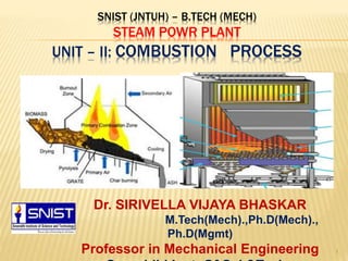
  • 1. SNIST (JNTUH) – B.TECH (MECH) STEAM POWR PLANT UNIT – II: COMBUSTION PROCESS 1 Dr. SIRIVELLA VIJAYA BHASKAR M.Tech(Mech).,Ph.D(Mech)., Ph.D(Mgmt) Professor in Mechanical Engineering
  • 2. Properties of Coal 2 2 1) Swelling index 2) Grindability 3) Weatherability 4) Sulphur content 5) Heating value 6) Ash softening temperature.
  • 3. Swelling Index 3 3 • Swelling index is a qualitative evaluation method, used to determine the extent of caking of a coal. • A free burning coal has a high value of swelling index, which indicates that it slightly expands in volume during combustion. • This swelling index is of importance for pulverised coal.
  • 4. Grindability 4  It is one the important properties in selecting the coal. This property is measured by standard grindability index  The grindability index is inversely proportional to the power required to grind the coal to a specified particle size for burning. 4
  • 5. Weatherability 5  It is a measure of how well coal can be stored for a long time with out crumbling to pieces.  Generally Modern power plants store coal supply for 90 days in large Trapezoidal piles.  Crumbling of coal due to climatic condition may result in small particles of coal which can be carried away by wind or rain. 5
  • 6. Sulphur content 6  Sulphur in coal is combustible and generates heat by its oxidation forming SO2 is very essential during combustion.  It is a major source of air pollution.  Its removal is very essential. 6
  • 7. Heating value / Calorific value 7  This property is of fundamental importance.  It is the heat transferred when the products of complete combustion of sample of coal are cooled to the initial temperature of air and fuel.  It is generally determined by Bomb calorimeter. Anthracite: 32,500 - 34,000 kJ/kg Bituminous coal: 17,000 - 23,250 kJ/kg Charcoal: 29,600 kJ/kg Coal: 15,000 - 27,000 kJ/kg Coke: 28,000 - 31,000 kJ/kg 7
  • 8. Ash Softening Temperature 8  The Ash softening temperature is the temperature at which the ash softens and becomes plastic.  This temperature is slightly less than melting temperature of ash.  This A.S.T. is an important factor in designing a steam generator.  For a furnace that would discharge ash in solid form, a high A.S.T. is required otherwise clinkers would be formed. It is difficult to remove these clinkers.  Failure to remove the ash and the clinkers results in inefficient combustion. 8
  • 9. 9 FIRING SYSTEM The firing system is mainly classified into two types 1) Hand firing 2) Stoker firing. Hand firing: • This is the simplest method of fuel firing. The combustion efficiency is very low, when compared to others. • Due to lower combustion efficiency it cannot be used in Modern power plants.
  • 10. Method of fuel firing : Hand firing  This is a simple method of firing coal into the furnace. It requires no capital investment. It is used for smaller plants.  Adjustments are to be made every time for the supply of air when fresh coal is fed into furnace.  Hand fired grates: used to support the fuel bed and admit air for combustion.  While burning coal the total area of air openings varies from 30 to 50% of the total grate area.  The grate area required for an installation depends upon various factors such as its heating surface, the rating at which it is to be operated and the type of fuel burnt by it.  The width of air openings varies from 3 to 12 mm.  The construction of the grate should be such that it is kept uniformly cool by incoming air. It should allow ash to pass freely.  Hand fired grates are made up of cast iron.
  • 11. 11 Stoker Firing • A stoker is a power- operated fuel feeding mechanism using a grate. • This method of firing is used for burning solid coal on a grate. Stoker are classified as follows: 1) overfeed stokers 2) underfeed stokers
  • 12. Classification of Stokers 12 Stokers Overfeed Stoker Travelling Grate Stoker Chain Grate Stoker Bar Grate Stoker Spreader Stoker Underfeed Stoker Single Retort Stoker Multi Retort Stoker
  • 13. 13 Over feed stokers • In the overfeed mechanism a forced draught fan slightly pressurizes the atmosphere air before it enters under the bottom of the grate. • The fuel bed receives fresh coal on top surface • The ignition zone lies between green coal and incandescent coke. • The air gets heated up as it follows through the grate openings where as the grate gets cooled. • This warm air gets additional heat energy by further passing through a layer of hot ashes.
  • 14. 14
  • 15. Primitive Method of solid Combustion Primary Air Secondary AirFlame Green Coal Incandescent coke Grate CO+CO2+N2+H2 VM+CO+CO2+N2+H2 O2+CO2+N2+H2O ASH
  • 16. OVER FEED STOKERS 16 Different types of over feed stokers: These type of stokers are used for large capacity boiler installations where the coal is burnt without pulverization. 1)Travelling grate stoker a) Chain grate type b) Bar grate type 2) Spreader stoker
  • 17. CHAIN GRATE STOKER 17  A chain grate stoker consists of an endless chain which forms a support for the fuel bed.  The chain surface is made of a series of cast iron links connected by pins. 
  • 18. CHAIN GRATE STOKER 18  The chain travels over two sprocket wheels located at the front and at the rear of the furnace.  The front sprocket is connected to a variable speed drive mechanism  Speed range 15 cm/ min to 50 cm/ min
  • 19. Chain grate stoker  The chain travels over two sprocket wheels, one at the front and one at the rear of furnace. The traveling chain receives coal at its front end through a hopper and carries it into the furnace.  The speed of grate (chain) can be adjusted to suit the firing condition.  The air required for combustion enters through the air inlets situated below the grate.  The stokers are suitable for low ratings because the fuel must be burnt before it reaches the rear of the furnace.
  • 20. CHAIN GRATE STOKER – ADVANTAGES & DISADVANTAGES 20 ADVANTAGES: 1) Simple in construction 2) Low initial cost. 3) Self-cleaning stoker. 4) The rate of heat release can be controlled just by controlling chain speed. 5) Rate of heat release is high per unit volume of furnace. DISADVANTAGES: 1) cannot be used for high capacity boilers. 2) temperature of pre-heated air limited to 180 0 C 3) clinker troubles are very common. 4) loss of coal in the form of fine particles - carried away with the ash.
  • 21. Spreader stoker 21  Spreader stoker mechanism involves throwing (spreading) the coal uniformly on the grate.  The grate may be of stationary or moving type, with air openings for admitting the air.  The selection of coal size is very important for a spreader stoker -- the coal size should be in between 6 cm to 36 cm.  The spreader stoker is mostly used for steam capacities of 9.5 to 50 kg/sec. (34 to 180 tonnes/hr)  It can burn a wide variety of coals from high ranking bituminous to lignite.
  • 22. 22
  • 24. Spreader Stoker 24 Advantages: 1) A wide variety of coal can be burnt. 2) The clinkering problems can be reduced by spreading action. 3) High temperature preheated air can be used. 4) Volatile matter is removed by burning coal in suspension. 5) Good response to load fluctuation. 6) Low running cost. Disadvantage:  Difficult to operate with varying sizes of coal with varying moisture content.  Fly ash is a major problem.  Fuel loss due to suspension and exhaust gases.
  • 25. UNDER FEED STOKERS 25 1) This underfeed mechanism is best situated for bituminous and semi bituminous coals. 2) In this underfeed mechanism the fuel is fed from underneath the fire and moves upwards gradually. 3) The air entering through the grate opening comes in contact with raw fuel and mixes with the volatile matter released from raw fuel and enters into the combustion chamber.
  • 27. UNDER FEED STOKERS 27 Different types of under feed stokers. 1) single retort stoker 2) multi-retort stoker. Single retort stoker  The single retort stoker consists of a trough shaped retort to which the fuel (coal) is fed by a reciprocating ram or screw conveyor.  The capacity of this stoker ranges from 100 to 2000 kg of coal burned per hour.
  • 28. MULTI RETORT STOKER 28  The coal falling from the hopper is pushed forward during the inward stroke of stoker ram. The distributing rams (pushers) then slowly move the entire coal bed down the length of stoker.  The slope of stroke helps in moving the fuel bed downwards.  The primary air enters the fuel bed from main wind box situated below the stoker. Partly burnt coal moves on to the extension grate.  The air entering from the main wind box into the extension grate wind box is regulated by an air damper.
  • 29. MULTI RETORT STOKER 29 The number of retorts may vary from 2 to 20 with coal burning capacity of 300 to 2000 kg/hr.
  • 30. MULTI RETORT STOKER - ADVANTAGES 30 1) High thermal efficiency when compared with chain grate stoker. 2) The grate is self cleaning. 3) Part load efficiency is high with multiple retort system. 4) high combustion rate. 5) wide variety of coals can be used. 6) best suitable for non-clinkering, high volatile and low ash content coals.
  • 31. MULTI RETORT STOKER DISADVANTAGES 31 1) Initial cost is high. 2) Large building area is required. 3) Clinker troubles are usually present. 4) Low grade fuels with high ash content cannot be burnt economically.
  • 32. Pulverized coal-fired boiler 32 • A pulverized coal-fired boiler is an industrial or utility boiler that generates thermal energy by burning pulverized coal (also known as powdered coal or coal dust since it is as fine as face powder in cosmetic makeup) that is blown into the firebox. • The basic idea of a firing system using pulverised fuel is to use the whole volume of the furnace for the combustion of solid fuels. • Coal is ground to the size of a fine grain, mixed with air and burned in the flue gas flow. Biomass and other materials can also be added to the mixture.
  • 33. Pulverized coal-fired boiler 33 • Coal contains mineral matter which is converted to ash during combustion. The ash is removed as bottom ash and fly ash. • The bottom ash is removed at the furnace bottom. • This type of boiler dominates the electric power industry, providing steam to drive large turbines. • Pulverized coal provides the thermal energy which produces about 50% of the world's electric supply.
  • 34. Pulverized Coal Power Plants-Current Technologies 34 Pulverized coal power plants are broken down into three categories; subcritical pulverized coal (SubCPC) plants, supercritical pulverized coal (SCPC) plants, and ultra- supercritical pulverized coal (USCPC) plants. The primary difference between the three types of pulverized coal boilers are the operating temperatures and pressures. • Subcritical plants operate below the critical point of water (647.096 K and 22.064 MPa). • Supercritical and ultra-supercritical plants operate above the critical point. As the pressures and temperatures increase, so does the operating efficiency.
  • 35. Requirements of Pulverised Fuel Firing 35 There are two requirements which are must for Pulverised Coal to burn successfully in a furnace. 1) Presence of large quantities of Fine particles of coal usually that would pass enough through a 200-mesh to ensure Spontaneous Ignition because of their large surface to volume ratio. 2) Presence of minimum quantity of Coarser particles to ensure High Combustion Efficiency.
  • 38. ADVANTAGES 38 1) Any grade of coal can be used efficiently because it is powdered before use. 2) Higher boiler efficiency due to complete combustion. 3) Flexible method and can respond well for sudden change in demand. 4) Fan power required is low. 5) Free from clinker problem. 6) Volume of the furnace required is less. 7) No major problem in ash handling.
  • 39. ADVANTAGES contd. 39 8) The system works successfully with or in combination with gas and oil. 9) No moving parts in the furnace are subjected to high temperatures. 10) Much smaller quantity of air is required as compared to the stoker firing. 11) The external heating surfaces are free from corrosion. 12) It is possible to use highly preheated secondary air (350 deg. C) which helps in rapid flame propagation.
  • 40. DISADVANTAGES 40 1) Additional investment for coal preparation unit/ plant. 2) Extra power is needed for pulverising coal. 3) Maintenance cost is more which depends on quality of coal. 4) Due to very high temperature, maintenance of furnace walls is difficult. 5) More space is required. 6) Special equipment is required to start the system.
  • 41. 41
  • 43. ADVANTAGES 43 1) Simple layout and easy operation. 2) It requires less space. 3) It is cheaper when compared with central system. 4) Less maintenance. 5) Simple coal transportation system. 6) Direct control of combustion from the pulveriser is possible. 7) Better control over fuel feed rate.
  • 44. DISADVANTAGES 44 1) Less flexible when compared to central system. 2) With the load factor in common practice, the total capacity of all the mills must be higher than for the control system. 3) Any fault in the coal preparation unit may stop the entire steam generating system. 4) Excessive wear and tear of the fan blades as it handles air and coal particles.
  • 45. 45
  • 46. ADVANTAGES 46 1) More flexible because the quantity of fuel and air can be controlled separately. 2) More reliable. 3) No problem of excessive wear of fan blades. 4) Less labour is required. 5) Low power consumption per tonne of coal handled.
  • 47. DISADVANTAGES 47 1) High initial cost. 2) It requires large space area. 3) Possibility of fire and explosion hazards. 4) Driers are necessary. 5) Operation and maintenance costs are high when compared to unit system of same capacity. 6) More number of auxiliaries.
  • 48. Disadvantages of Pulverised Coal Burners 48 The pulverised coal burners have the following disadvantages 1) The capital and running costs of pulverised units are considerable. 2) About 70% of the ash in coal, goes with exhaust gases in the form of fly ash requiring expensive dust collectors in the gas circuit. To overcome these disadvantages cyclone burner concept is used. In these cyclone burners crushed coal particles are burnt in vortex suspension.
  • 49. pulverized fuel plants Basically, pulverized fuel plants may be divided into two systems based on the method used for firing the coal:  Unit System or Direct System  Bin System or Central System  Unit or Direct System: This system works as follows:  Coal from bunker drops on to the feeder.  Coal is dried in the feeder by passage of hot air.  The coal then moves to a mill for pulverizing.  A fan supplies primary air to the pulverizing mill.  Pulverized coal and primary air are mixed and sent to a burner where secondary air is added.
  • 50.  Bin or Central System:  Coal from bunker is fed by gravity to a dryer where hot air is admitted to dry the coal.  Dry coal is then transferred to the pulverizing mill.  Pulverized coal then moves to a cyclone separator where transporting air is separated from coal.  Primary air is mixed with coal at the feeder and supplied to the burner.  Secondary air is supplied separately to complete the combustion
  • 52. Types of Burners for Pulverized Coal  Various types of burners are used for combustion of pulverized coal.  Long Flame (U-Flame) Burner: In this burner, air and coal mixture travels a considerable distance thus providing sufficient time for complete combustion
  • 53. Cyclone Burner 53  In this system, the coal and air will be mixed due to cyclonic whirling action  The coal is crushed into tiny powder in addition to pulverized coal The ash is easily collected due to cyclonic action
  • 55.  Cyclone Burner: In this system, the cyclonic action whirls coal and air against the wall of the furnace to facilitate thorough mixing of coal and air.  Advantage of this burner is that it can also use crushed coal in addition to pulverized coal thus providing an option.  When crushed coal is used, ash is collected in molten form for easy disposal. 
  • 56. ADVANTAGES 56 1) Costly pulverisers are not required. Instead, simple coal crushing equipment can be used. 2) By using forced draught fan it can be operated with small quantities of excess air. 3) It can burn low grades of coal effectively. 4) High temperatures are obtained. 5) Boiler fouling (sticking) problems can be reduced as all the incombustibles are retained in the cyclone burner. 6) Boiler efficiency is increased.
  • 57. Exhaust Gas - Draught System 57  The small pressure difference which causes a flow of gas to take place is termed as draught.  The function of draught is to force air to the fire and to carry away the gaseous products of combustion
  • 58. Draught System 58 Natural Draught:  Natural draught is obtained by the use of a Chimney.  Chimney produces the draught whereby the air and gas are forced through the fuel bed, furnace, boiler passes and settings  Chimney carries the products of combustion to such a height before discharging them to atmosphere
  • 59. Draught System 59 Natural Draught:  A chimney is vertical tubular structure built either of masonry, concrete or steel.  The draught produced by the chimney is due to the density difference between the column of hot gases inside the chimney and the cold air outside.
  • 60. Draught System - Artificial Draught 60  Total static draught required from 30 to 350 mm of water column and it is not possible to build a chimney high enough to produce draught of such large magnitude. So for this purpose we are using the artificial draught  It may be mechanical or steam jet draught  Mechanical system used in the central power stations  Steam jet system used for small installations and in locomotives
  • 61. Forced Draught System 61  In a mechanical draught system, the draught is produced by a fan.  In a forced draught system a blower or fan is installed near or at the base of the boiler to force the air through the cool bed and other passages through the furnace , flues, air preheater, economizer etc.  The enclosure for the furnace has to be very highly sealed so that gases from the furnace do not leak out in the boiler house
  • 63. Induced Draught System 63 • In this system fan or blower is located near the base of chimney • The pressure over the fuel bed is reduced below that of atmosphere • By creating the partial vacuum in the furnace and flues, the products of combustion are drawn from the main flue and they pass up the chimney • This draught is usually operative when economizers and air preheater are incorporated in the system • The draught is similar in action to the natural draught.
  • 65. Balanced Draught 65  It is the combination of the forced and induced draught system  The forced draught fan overcomes the resistance in the air preheater and chain grate stoker while the induced draught fan overcomes the losses through boiler, economiser, air preheaters and connecting flues.  Advantages over induced draught:  Forced draught fan does not require water cooled bearings  Tendency to air leaks into the boiler furnace is reduced  No loss due to inrush of cold air through the furnace doors  Fan size and power required for same draught is less because forced draught fan handles cold air
  • 66. Advantages of Mechanical Draught 66  Easy control of combustion and evaporation.  Increase in evaporative power in boiler  Improvement in the efficiency of the plant  Reduced chimney height  Prevention of smoke  Capability of consuming low grade fuel  Low grade fuel can be used as the intensity of artificial draught is high  The fuel consumption per kW due to artificial draught is 15% less than that for natural draught  The fuel burning capacity of grate is 200 to 300 kg/m²-hr with mechanical draught and it is 50 to 100 kg/m²-hr with natural draught
  • 67. Steam Jet Draught 67  It is simple and easy to produce artificial draught  It may be forced or induced type depending upon where the steam jet to produce draught is located  If the steam jet is directed into the smoke box near the stack the air is induced through the flues, the grate and ash pit to the smoke box.  If the jet is located before the grate air is forced through the fuel bed, furnace and flues to the chimney.  Advantages:  Very simple and economical  Occupies minimum space  Several low grade fuels can be used  Requires very little attention
  • 68. COOLING TOWERS 68  In power plants the hot water from condenser is cooled in cooling tower, so that the water can be reused in condenser for condensation of steam.  In a cooling tower water is made to trickle down drop by drop so that it comes in contact with the air moving in the opposite direction.  So that some water is evaporated and is taken away with air.  In evaporation the heat required for the evaporation is taken away from the bulk of water which is thus cooled.
  • 69. COOLING TOWERS contd. 69  Factors affecting cooling of water in a cooling tower are:  Temperature of air  Humidity of air  Temperature of hot air  Size and height of tower  Velocity of air entering the air  Accessibility of air to all parts of tower  Arrangement of plates in tower  Cooling towers are classified as  Natural draught cooling towers  Mechanical draught cooling towers  i) forced draught cooling towers  ii) induced draught cooling towers
  • 70. Natural Draught Cooling Towers 70  In this type of tower the hot water from the condenser is pumped to the troughs and nozzles situated near the bottom.  Troughs spray the water falls in the form of droplets into a pond situated at the bottom of the tower.  The air enters the cooling tower from air openings provided near the base, rises upwards and takes up the heat of falling water.
  • 71. Hyperbolic Cooling Towers 71  The Advantages of the Hyperbolic Cooling Towers over mechanical towers are:  Low operating and maintenance cost  It gives more or less trouble free operation  Less ground area required  Cooling tower structures are self supported and withstands high speed of winds  The enlarged top of the tower allows water to fall out of suspension.
  • 72. Hyperbolic Cooling Towers 72  The Drawbacks of Hyperbolic Cooling Towers are:  High initial cost  Performance varies with DBT (dry bulb temp) and RH (relative humidity) of the air  While initial cost may be higher, the saving in fan power, longer life and less maintenance always favour for this hyperbolic cooling tower.
  • 73. Mechanical Draught Cooling Towers 73  In these towers the draught of air for cooling the tower is produced mechanically by means of propeller fans.  These are built in cells or units, the capacity depending on the number of cells used.  Advantages  These towers require a small land area and built in all locations  The fans give a good control over the air flow and water temperature.  Less costly to install than natural draught towers
  • 74. Mechanical Draught Cooling Towers 74 Disadvantages  Fan power requirements and maintenance costs make them more expensive to operate  Local fogging and icing may occur in winter season
  • 75. Forced Draught Cooling Towers 75  This is similar to natural draft tower as far as construction is concerned but the sides of the tower are closed and form an air and water tight structure, except for fan openings at the base for the inlet of fresh air and the outlet at the top for the exit of air and vapours.  There are hoods at the base projecting from the main portion of tower where the fans are placed for forcing the air into tower.
  • 76. Forced Draught Cooling Towers contd. 76  Advantages  More efficient than induced draught  No problem of fan blade erosion because it handles dry air only  More safe  The vibration and noise are minimum  Disadvantages  The fan size is limited to 4 metres  Power requirement is high  In cold weather, ice is formed on equipments and the frost in the fan outlet can break the fan blades
  • 77. Induced Draught Cooling Towers 77  In these towers fans are placed at the top of the tower and they draw the air in through louvers extending all round the tower at its base.  Advantages:  Lower the first cost  Less space requirement  Capable of cooling wide range  Coldest water comes in contact with driest air and warmest with humid air  Recirculation is seldom a problem  Disadvantages:  air velocities are unevenly distributed  Static pressure loss is higher because base tends to choke at high velocity pressures
  • 78. Basic Principles of Mechanical Dust Collectors 78  Enlarging the duct cross sectional area to slow down the gas gives the heavier particles a chance to settle out.  When a gas makes a sharp change in flow direction, the heavier particles tend to keep going in the original direction and so settle out.  Impingement baffles have more effect on the solid particles than the gas, helping them to settle.
  • 79. DUST COLLECTORS 79  Dust collectors are grouped into two types 1.Mechanical Dust Collectors i) Wet type dust collectors ii) Dry type dust collectors • Gravitational separators • Cyclone separators 2.Electrical Dust Collectors i) Rod type ii) Plate type
  • 80. Mechanical Dust Collectors 80 i) Wet type dust collectors:  Wet types called scrubbers operate with water sprays to wash dust from the air.  Large quantities of wash water are needed for central station gas washing that this system is seldom is used.  It also produces a waste water that may require chemical neutralization before it can be discharged into the central bodies of water. ii) Dry type dust collectors: These are commonly used dust collectors.  Gravitational Separators: These collectors act by slowing down gas flow so that particles remain in a chamber long enough to settle in the bottom. They are not very suitable because of large chamber volume needed.  Cyclone Separators
  • 81. Cyclone (or) Centrifugal separator 81 • The cyclone is a separating chamber where in high-speed gas rotation is generated for the purpose of centrifuging the particles from the carrying gases. • There is an outer downward flowing vortex which turns into an inward flowing vortex. • Involute inlets and sufficient velocity head pressures are used to produce the vortices. • The factors which affect the performance are gas volume, particles loading, inlet velocity, temperature, diameter- to- height ratio of cyclone and dust characteristics.
  • 82. Advantages and Disadvantages of Cyclone Separator 82 ADVANTAGES:  Rugged in construction  Maintenance costs are relatively low  Efficiency increases with increase in load  Easy to remove bigger size particles DISADVANTAGES:  Requires more power than other collectors  Incapable to remove dust and ash particles which remain in suspension with still air  Less flexible  High pressure loss  Requires considerable head room and must be placed outside the boiler room
  • 83. Electrical Dust Collector 83 The main elements of an electrostatic precipitator are:  Source of high voltage  Ionizing and collecting electrodes  Dust removal mechanism  Shell to house the elements
  • 84. Electrical Dust Collector 84  The precipitator has two sets of electrodes, insulated from each other, that maintain an electrostatic field between them at high voltage  The field ionizes dust particles that pass through it, attracting them to the electrode of opposite charge.  The high voltage system maintains the negative potential of 30,000 to 60,000 volts with the collecting electrodes grounded.  Accumulated dust falls of the electrode when it is rapped mechanically  Wet type of unit removes dust by a water film flowing down on the inner side of the collecting electrode.  These units have collection efficiency around 90%
  • 85. Electrical Dust Collector 85 ADVANTAGES:  Can effectively remove very small particles like smoke, mist and fly-ash  Easy operation  Draught loss is quite less  Most effective for high dust loaded gas  Maintenance charges are minimum  The dust collected in dry form and can be removed either dry or wet DISADVANTAGES:  Space requirement is more  Need to protect the collector from sparking  Running charges are high  Capital cost of equipment is high
  • 86. Efficiency of Dust Collectors 86  The collection efficiency of a dust separator is the amount of dust removed per unit weight of dust.  Though dust collectors remove contaminants, they increase draught losses and hence the fan power.  The absolute efficiency of a dust collector is the percentage of entering solids that will be removed by the collector.
  • 87. Layout of Dust Collection System 87
  • 88. FEED WATER TREATMENT 88 Classification of impurities in water 1. Visible Impurities  Microbiological growth: Presence of micro-organisms is always undesirable as they may produce clogging troubles  Turbidity and sediments: Turbidity is the suspended insoluble matter where as sediments are the coarse particles which settle down in stationary water, both are objectionable 2. Dissolved Gases  Carbon dioxide  Oxygen  Nitrogen  Methane  Hydrogen Sulphide 3. Minerals and Salts  Iron and Manganese  Sodium and Potassium salts  Fluorides  Silica
  • 89. FEED WATER TREATMENT contd. 89 4. Mineral Acids Their presence in water is always undesirable as it may result in the chemical reaction with the boiler material. 5. Hardness  Presence of these salts is known as hardness  The salts of calcium and magnesium as bicarbonates, chlorides, sulphates etc are mainly responsible for the formation of a very hard surface which resists heat transfer and clogs the passage in pipes.
  • 90. Troubles Caused By The Impurities In Water 90 1. Scale formation  The formation of scales reduces the heat transfer and simultaneously raises the temperature of the metal wall.  Scale is due to salts of Calcium and Magnesium and Silicates  Scales choke the flow of the piping system and requires increased pressure to maintain water delivery.  Resulting overheating, blistering and rupturing.  When scale is formed tubes are cleaned with electric powered rotary brushes and cutters are pushed though the tubes during boiler overhaul.
  • 91. Troubles Caused By The Impurities In Water 91 2. Corrosion  Corrosion is the eating away process of boiler metal.  It is caused due to acids or low pH in addition to the presence of dissolved oxygen and carbon dioxide in the boiler feed water.  Corrosion can be reduced by adding alkali salts to neutralize acids in water and raise the pH value.  The effect of CO2 neutralizes by adding the ammonia for neutralizing amines in water.  The effect of oxygen is reduced by removing the oxygen from water  The effect of corrosion is prevented by applying protective coating of amines to the internal surfaces of boilers and economizers.
  • 92. Troubles Caused By The Impurities In Water 92 3. Carry over  Water solids carried over in the steam leaving a boiler drum are called carry over.  Foaming or priming of the boiler water forms the carry over  Bubbles formed on the water surface is called foaming  Foaming causes due to excessive amounts of sodium alkalinity  Priming refers to the vigorous and periodic surging of water in the boiler drum  Foaming and priming are caused due to excessive steaming rate, too high or fluctuating water level and improper boiler water circulation.  Foaming and priming can be checked by following precautions  Valves do not open suddenly to maximum  Water level should be minimum level  Water should not contain oil, soap and suspended impurities
  • 93. Troubles Caused By The Impurities In Water 93 4.Embrittlement  The caustic Embrittlement is the weakening of boiler steel as a result of inner crystalline cracks.  Presence of sodium hydroxide causes Embrittlement.  Methods to control Embrittlement are  Elimination of free sodium hydroxide from boiler water  Maintenance of correct ratio of sodium nitrate to sodium hydroxide  Using waste sulphite liquor.
  • 94. METHODS OF FEED WATER TREATMENT 94 1. Mechanical Treatment : used for suspended solids  Sedimentation  Coagulation  Filtration  Interior painting 2. Thermal Treatment: used for dissolved gases  De-aeration  Distillation by evaporators 3. Chemical Treatment: used for dissolved solids  Cold lime soda softening process  Hot lime soda softening process  Lime phosphate softening process  Ion exchange process or sodium zeolite or hydrogen zeolite process 4. Demineralisation 5. Blow down  Hot lime soda and hot zeolite process  Adding acids to control alkalinity and vice versa
  • 95. MECHANICAL TREATMENT 95 Sedimentation:  In this process the water is allowed to stand at stand still in big tanks so that solid matter settles down.  The water at a very low velocity will also have the same process  These solids are settled down and removed from the bottom wither periodically or continuously.  Clear water is then drained out from the tank surface Coagulation:  Coagulation of minute colloidal suspensions makes then settle out easily.  Adding coagulation like aluminium sulphate or sodium aluminate improves the sedimentation or filtration process.  A reaction between these salts and alkalinity in the water forms a gelatinous material which makes small particles adhere to each other, forming larger particles that settle out or filter out more easily.
  • 96. MECHANICAL TREATMENT 96 Filtration  The suspended matter which can not be removed during sedimentation is removed with the help of filtration.  The water is allowed to pass through a bed of fine sand or graded sand and then a layer of gravels.  The suspended matter adheres to the filter material leaving the water clear as it drains from the bottom.  The bed must be backwashed periodically to remove dirt that collects in the voids of the filter material.  In the pressure filter the water is forced through the filter by means of a pump whereas in gravity filters the water flows by gravity.
  • 97. 97
  • 98. THERMAL TREATMENT Deaeration  The process of removing dissolved oxygen is known as Deaeration.  If the water is heated to 110º C with suitable agitation the dissolved oxygen is expelled.  In this tray type deaerating heater feed water after passing through the vent condenser is sprayed upwards in the spray pipe.  Water falls in the form of uniform showers over the heating trays and air separating trays and finally collected in the storage space.  Steam enters the heaters through a nozzle fitted in the side of the heater shell.  The steam makes its way downwards though the perforations in the top plate of tray compartment.  While flowing downwards the steam comes in contact with the falling water.  Most of the steam condenses in between the spray and heating trays.  From the bottom of heating trays, the remaining steam and separated gases flows to the cent condenser.  The steam used for heating may be from turbine bled steam or 98
  • 99. 99
  • 100. THERMAL TREATMENT 100 Distillation by Evaporators  An evaporator’s function is to produce from raw water, vapour that can be condensed to distilled water for boiler feed make up.  In the regenerative cycle the evaporator is useful as the steam used for evaporation is being used in the feed water itself.  It has the advantage of requiring lesser blow down of deconcentration in the boiler.  An evaporation system may be single effect where steam produced from one evaporator or multiple effects in which steam is produced from several evaporators in series.  They also classified as film type, flash type and submerged tube type.
  • 101. CHEMICAL TREATMENT 101 Lime Soda Softening Process  This process uses calcium hydroxide and sodium carbonate, to remove dissolved calcium and magnesium salt, by precipitating them.  This may be done by cold process or hot process.  The processes use these types of reactions: All the carbonate hardness is precipitated out, leaving pure water. The non-carbonate hardness precipitates, to be replaced by soluble sodium salts.
  • 102. Lime Soda Softening Process 102  The magnesium hydroxide [Mg(OH)2] acts as a coagulant and has the property of absorbing soluble silica from solution.  Hot process phosphate softening uses trisodium phosphate and caustic soda to precipitate and remove calcium and magnesium hardness.  The reactions are as follows:  Phosphates also remove silica compounds, which are troublesome in high pressure boilers.  Phosphate chemicals cost more than lime soda.
  • 103. ION EXCHANGE PROCESS 103 Sodium Zeolite Process  The zeolites are solid materials of a sandy texture.  They remove various ions from the water replacing them with other ions of like charge.  In Sodium zeolite the reactions are as followed where z is the symbol used for zeolite
  • 104. 104
  • 105. Sodium Zeolite Process 105  Zeolite softener consists of shell holding a bed of active sodium zeolite supported by layers of graded gravel lying over a water distribution and collection system.  Zeolite completely remove hardness but reduce alkalinity or total solids.  Turbid water does not react with zeolite salts, they remove silica and may add it.  The exhaustion capacity of the zeolite bed should be known, because regeneration should be started as soon as the exhaustion starts.  First back washing should be done by passing a strong current of water upwards.  A measured quantity of common salt solution should be injected in the softner.  The salt reacts with the zeolite thus removing magnesium in the form of soluble chlorides.  After salt rinse zeolite filter is ready to be used again.  The equation of this reaction is  The entire process regeneration period is about 4 minutes.
  • 106. ION EXCHANGE PROCESS 106 Hydrogen-Zeolite process:  Non silicious materials can be used to exchange the hydrogen ions for cations as calcium and magnesium.  The synthetic zeolites developed are sulphonated coal and polystyrene resins which withstand acid and regenerated with acid could be used to exchange hydrogen for the metals of salt in solution.  The equations for the reactions are  The main merit of this process is that the water in carbonates including sodium carbonate or bicarbonate can be softened easily without replacing the water with some other salt.
  • 107. DEMINERALISATION 107  The mineral content of water may be removed by evaporation or by series of cation and anion exchangers to produce essentially distilled water.  Demineralisation is often the most economical method to producing make up water for HP boilers.  In the diagram shows the series process for demineralisation.  A simple demineraliser uses only the first two units.  Strong base anion exchange materials absorbs weak acids as well as strong acids.  Weak base anion exchange materials are used for removing chlorides, sulphates and nitrates.
  • 108. BLOW DOWN 108  There may be some dissolved solids in the water entering the boiler .  As the water gets evaporated the concentration of these solids goes on increasing.  Beyond a certain limit of concentration these solids may cause foaming and priming.  The concentration of these solids can be reduced by drawing off some of the quantity of the boiler water from the bottom of the boiler drum.  This is called blowing down and discharged water is known as blow down.
  • 109. pH VALUE OF WATER. 109  pH value of water is the logarithm of the reciprocal of hydrogen ion concentration.  It varies from 0 to 14 with 7 indicating neutral water.  Water sample which is having pH value less than 7 indicates Acidity of water and pH value more than 7 are Alkaline.  Acidic or alkaline nature of water depends upon whether the hydrogen or hydroxyl ions predominate.  In a mixture of bases and water, hydroxyl ions result.  Hydrogen ions make a solution acidic where as hydroxyl ions make it alkaline.  When a sample contains one (OH) ion for every (H) ion, the acid effect of one balances the alkaline effect of the other.  Result is a neutral solution with a pH value of 7.0  This pH value of water can be determined by a pH meter.  The pH meter is essentially a comparator which compares  sample colour with that of many standards to determine the value.