Download
1 / 25
850 likes | 2.5k Views
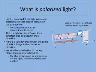
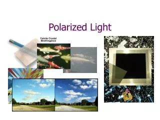
Lecture 18. OA. Extraordinary ray. Double refraction. Ordinary ray. OA. 2 images through calcite crystal. Polarizer transmits ordinary ray. Polarizer rotated about 90 transmits extraordinary ray. Production of polarized light through birefringence.

E N D
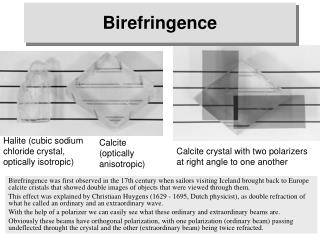
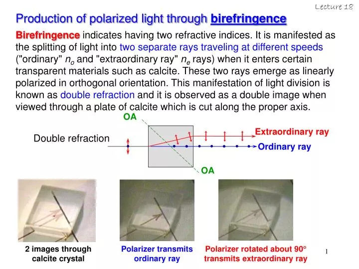
Lecture 18 OA Extraordinary ray Double refraction Ordinary ray OA 2 images through calcite crystal Polarizer transmits ordinary ray Polarizer rotated about 90 transmits extraordinary ray Production of polarized light through birefringence Birefringence indicates having two refractive indices. It is manifested as the splitting of light into two separate rays traveling at different speeds ("ordinary" no and "extraordinary ray" ne rays) when it enters certain transparent materials such as calcite. These two rays emerge as linearly polarized in orthogonal orientation. This manifestation of light division is known as double refraction and it is observed as a double image when viewed through a plate of calcite which is cut along the proper axis.
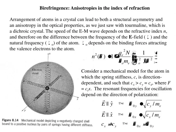
x z y How did birefringence come about in materials? • Birefringent material are optically anisotropic. • The anisotropic oscillator may be imagined as a charged shell bound by strings of different stiffness, i.e., different spring constant • Electrons displaced from equilibrium along direction parallel to one set of “springs” will oscillate with different characteristic frequency than it would when displaced in other directions. Light propagates through transparent medium by exciting the atoms. Electrons driven by the E-field will reradiate. These secondary wavelets recombine, and resultant refracted wave moves on. The speed of the wave, and therefore the index of refraction, is determined by the difference between the frequency of the E-field and the natural frequency of the atoms.
x z y How did birefringence come about in materials? Anisotropy in the binding force will result in anisotropy in the refractive index. Thus, if a polarized light traverses such crystal, its speed is dictated by the orientation of E. E.g., if E is parallel to stiff spring (in direction of strong binding, x-axis in the figure), the natural frequency of the electron would be high ( square root of spring constant) If E is parallel to y-axis (low spring constant), where the binding force is weaker, natural frequency will be lower. This will result in two different refractive indices along the x-axis, nx and the y-axis, ny, each with its own dispersion curve (n vs. )
n() Absorption band ny 1 n() Absorption band nx 1 b d How did birefringence come about in materials? If incident light has ~ d, Ey is absorbed but Ex is transmitted dichroism But if incident light has ~ b, both the Ey and Ex are transmitted with different speeds birefringence Examples of birefringent materials in the VISIBLE spectrum are: CALCITE(but dichroic in certain parts of IR spectrum); QUARTZ; ICE; MICA; CELLOPHANE Refractive index vs. frequency along two axes in a crystal. Shaded regions where dn/d < 0 correspond to absorption bands.
Each CO3 group forms a triangular cluster, its plane perpendicular to the optic axis Arrangement of atoms in CALCITE (CaCO3) Atomic arrangement for calcite looking down the optical axis. It has 3-fold symmetry - if above figure is rotated about line normal to and passing through center of any CO3 groups, same exact configuration of atoms will appear 3 times during each revolution. Optic axis is line // to line joining C and Ca atoms CALCITE a birefringent material in VIS spectrum
Calcite cleavage form has 2 blunt corners (surface planes meet to form 3 obtuse (<90) angles) Line passing through vertex of eitherblunt corners, oriented such that it makes equal 45.5 with each face, and 63.8 with each edge is the axis of 3-fold symmetry optic axis CALCITE a birefringent material in VIS spectrum • Large birefringence of Calcite arises from the CO3 groups being in planes normal to optic axis, thus the mutual interaction of induced oxygen dipoles is distinctly different when E is either in or normalto these planes (asymmetry); Calcite is also know as Iceland spar • Calcite can easily be split at cleavage planes (at which the interatomic bonding is relatively weak) • basic cleavage formof calcite is arhombohedron(each face is a parallelogram with angles 78 5’ and 101 55’)
CALCITE a birefringent material in VIS spectrum • What is the consequence? • Double image is seen • beam of natural light normal to cleavage plane splits and emerge as 2 parallel beams • Observed phenomenon: • A calcite crystal placed over a dot on a page will reveal two distinct images of the dot. One image will remain fixed as the crystal is rotated, and that ray through the crystal is called the "ordinary ray" (o-ray) since it behaves just as a ray through glass. However, the other image will rotate with the crystal, tracing out a small circle around the ordinary image. This ray is called the "extraordinary ray” (e-ray). The o- and e-rays are linearly polarized and they are orthogonal. (see slide 2)
3 Oxygen atoms form base of a tetrahedron, optic axis parallel to line joining Ca and C atoms. Figure shows unpolarized light propagating through calcite crystal from two different directions. (2) (1) CALCITE a birefringent material in VIS spectrum Direction (1): E-field resolved into two orthogonal E-components which are both perpendicular to optic axis. Both the resolved E-vibrations interact with electrons in the same way since the molecule is symmetric with respect to this direction. Direction (2): E-field resolved into two orthogonal E-components (one being parallel and the other is perpendicular to optic axis.) Thus, the resolved E-vibrations have dissimilar effects on the electrons in the base plane. E// component makes electrons oscillate along direction perpendicular to base plane; E causes oscillations within the plane
Refractive indices for various materials measured at Na wavelength of 589.3 nm. Uniaxial positive when n// n > 0; uniaxial negative when n// n < 0 CALCITE a birefringent material in VIS spectrum E-oscillations within plane - due to smaller binding forces - occur more easily than oscillations (E//) perpendicular to the plane. Since E-vibrations (E) in oxygen plane interact more strongly, its speed v < v//. And since refractive index n = c/v, therefore, n (or no) > n// (or ne)
OA OA OA CALCITE a birefringent material in VIS spectrum Note: E-components are either // or to OA; thus emerging beam remains a single beam. (a) Light propagation along optic axis; both E-components are OA, thus, both propagate at same speed through crystal with same n (b) and (c): One E-component is OA and the other is // OA thus, each propagates through crystal with different n and v Emerging beam (after traversing distance d in crystal) has cumulative relative phase difference of: QWP has thickness that yields = /2 (too thin) HWP has thickness that yields = Practical QWP: = (2)m+ /2; m = 1, 2, 3, ... (18-1) where = path difference, 0 = vacuum wavelength
OA Extraordinary ray Double refraction Ordinary ray OA Double refraction in CALCITE If OA is at an arbitrary angle to the beam direction (not 0 nor 90), the light beam undergoes double refraction, and o- and e-rays emerge. e-ray does NOT obey Snell’s law. O-ray is polarized OA, thus, propagates with no = n = c/v E-ray is polarized in direction polarization of O-ray; or has polarized components // and to OA; component propagates with speed v = c/n (like the o-ray) and // component propagates with speed v// = c/n//; net effect is the unusual bending of the e-ray
Polarization of Polychromatic light: Putting a retardation plate between crossed polarizer, we can observe complementary colours (as their combination yields white light) by rotating the analyzer by 90. (Say HWP at red light, red light will be fully transmitted through the crossed polarizer, whereas shorter VIS wavelengths will only be blocked/partially transmitted. If TA of analyzer is rotated 90, red will be blocked while the others transmitted.) As the phase difference introduced by retardation plate is wavelength and thickness(material) dependent; a crumpled piece of cellophane placed between crossed polarizers will show variety of colours, depending on how many layers it has gone through. Turning analyzer 90 will yield its complementary colours. Cellophane made from regenerated cellulose extracted from cotton or wood pulp. It is formed into sheets whereby the molecules becomes aligned, making it birefringent. Cellophane acts as HWP.
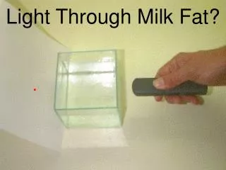
Summary on processes that produces polarized light (1) Dichroism - due to asymmetry optical property of dichroic material, it selectively absorbs light with E-component along a unique direction characteristic of the material, and easily transmits light along a transverse direction (transmission axis) orthogonal to the direction of absorption, resulting in a linearly polarized beam (or plane-polarized). (2) Reflection - when an unpolarized beam is incident on a dielectric surface, the reflected beam will be partially polarized having a predominance of Es component ( plane of incidence) while the refracted beam will also be partially polarized with predominance of Ep component (// plane of incidence). At Brewster’s angle the reflected beam will be completely linearly polarized. (3) Scattering - the orthogonal E-components of unpolarized light incident on particles/molecules (acting as electronic oscillators) set them into forced vibrations, producing radiation re-emitted in all directions. The scattered light will have maximum vibrations identical to the E-components such that when viewed from these orthogonal directions, linearly polarized light is seen. Viewed along directions off the axes of the E-components, the light is partially polarized. (4) Birefringence - refers to materials having two refractive indices due to anisotropy. It is manifested as double refraction, that is, the unpolarized light that propagates through the material is split into two orthogonal beams, the ordinary and extraordinary parts, each having speeds v and v// respectively.
Optical Activity Linearly polarized light when incident on an optically active material will emerge as a linearly polarized light but with its direction of vibration rotated from the original. Viewing beam head-on: clockwise rotation (dextrorotatory; right-handed) anti-clockwise rotation (levorotatory; left-handed) Examples of optically active materials: solids (quartz, sugar crystals) liquids (turpentine, sugar solution)
Optical Activity The d- or l-rotatory behaviour corresponds to two different crystallographic structures of quartz. Even though quartz molecules (SiO2) are identical, there are two arrangement of the molecules, each being a mirror image (or enantiomorphs) of the other. Optically active materials modify the state of polarization; this is the rotator mechanism, differs from that of the retarder (QWP, HWP)
Optical Activity Arrangement to measure optical activity. Polarizer & analyzer initially set at total extinction with their TAs orthogonal. Then the optical active cell is placed in-between them, total extinction disappears. Analyzer has to be rotated through for total extinction. Angle of rotation depends on wavelength of light and thickness of medium. Definition of specific rotation in: Solids - rotation (in degrees) produced by 1-mm plate of optically active material Liquids - rotation due to a 10-cm thickness and concentration of 1 g of active solute per cm3 of solution
Optical Activity Net angle of rotation due to light path L (in dm) through a solution of d grams of active solute / cm3 is: = Ld (18-2) When white light traverses through an optically active medium, each component wavelengths will be rotated through a slightly different degree, thus, the colours are separated (rotatory dispersion). Rotation for different colours by a plate of quartz 1mm thick A R Y G B V How does optical activity arise? Assume: (1) Linearly polarized light consists of equal amplitudes of left- (EL) and right-circularly (ER) polarized light. (2) Left- and right-circularly polarized components move through the optically active material with different velocities, vL & vR respectively (they have corresponding refractive indices nL & nR as v = c/n and considered to have circular birefringence)
t1 t2 t3 How does Optical Activity arise? In inactive medium, vL = vR, or equivalently, nL = nR and kL = kR (k = propagation vector with magnitude given by k = /v) A linearly polarized light in x-direction resolved into its left- and right-circularly polarized states will have a resultant vector sum E whose oscillations are along the x-axis (as ER and EL rotates clockwise and anti-clockwise at equal rates) Superposition of left- and right-circularly polarized light at different times. Resultant E-oscillations always along x-axis for inactive medium. Light assumed to be emerging from screen.
How does Optical Activity arise? In active medium, vLvR, or equivalently, nLnR and kLkR, thus, phases of L- and R- components are not equal, i.e., (18-3) where kL= (/c) nL and kR = (/c)nR The complex amplitudes written in vector form are: (18-4) Phases of the L- and R- components are: (18-5) The resultant is: (18-6)
How does Optical Activity arise? • The two components have the same time dependence and are therefore in-phase anywhere along direction of propagation (z-direction in this case), the resultant is linearly polarized but its orientation is a function of z. • As the two components are of equal amplitudes, the resultant E-oscillation is the diagonal of an equal-sided parallelogram, so that the angle rotated is given by: (18-7) • Substituting (18-5) into (18-7): (18-8) • Using the relations: • We have: (18-9)
Angle of rotation in optically active medium • At incidence on an optically active material, the linearly polarized light is immediately resolved into L- and R- circular modes (z = 0 and t = 0, the modes begin with L= R = 0) • If vR > vL, the R-mode reaches some point along its path before the L-mode • Until the L-mode arrives, E rotates at this point according to the circular polarization of R-mode acting alone • As soon as the L-mode arrives, the two modes superpose to fix the direction of vibration at an angle in a linear mode. (thus relative phase between the two modes at this instant given by Eq. 18-7 determines the angle ) • When vR > vL or nL > nR, right-handed rotation (dextro-rotatory) results (looking into source), positive – rotated clockwise • when vR < vL or nL < nR, left-handed rotation (levo-rotatory) results (looking into source), negative
Angle of rotation in optically active medium The superposition of an R- and L-state at z = d (kL > kR, L < R, and vL < vR). Refractive indices for quartz:
Quantitative example Find the rotation produced by a 1-cm thick quartz plate at a wavelength of 396.8 nm. What is its specific rotation? Solution: At = 396.8 nm, nL nR= 1.55821 1.55810 = 0.00011 From Eq. (18-9), the rotated angle is The specific rotation = angle of rotation produced by 1-mm thick:
Optic axis Simple explanation on why velocities of L- and R- circularly polarized modes differ. Optically active materials possess molecules or crystalline structures that have spiral shapes, with either left- handed or right-handed screw forms. Linearly polarized light transmitted through a collection of such molecules creates forced vibrations of electrons, that, in response, move along a spiral as well as around the spiral. Effect of L- circularly polarized light on a left-handed spiral would be different from its effect on a right-handed spiral. This leads to different speeds through the material. Right-handed quartz
Photoelasticity Photoelasticity – birefringence induced by mechanical stress applied to normally isotropic substances such as plastic or glass. Birefringence induced is proportional to strain. Photoelastic stress patterns for a beam resting on two supports: (upper photo) lightly loaded at the center; (lower photo) heavily loaded at the center. Where are the points under stress?