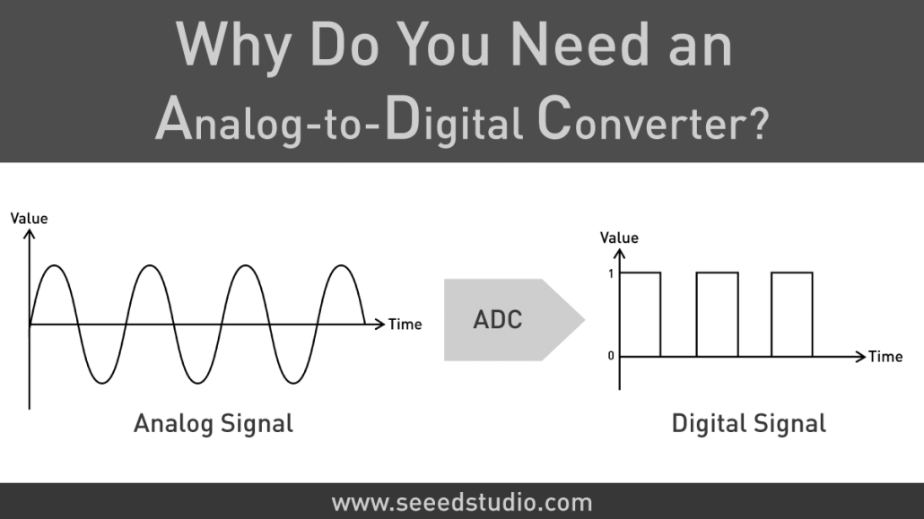
Why Do You Need an Analog-to-Digital Converter (ADC)?
You might be thinking, when would I need an Analog-to-Digital Converter (ADC) in my application? But do you know ADC is far more common than you think! Let’s look at what exactly is ADC, to begin with.
Introduction
When we build projects using an Arduino or a Raspberry Pi, we normally would connect different sensors to obtain information regarding the physical world and do some processing based on that information. So, when talking about communication, there are two types of signals that we often come across:
- Analog Signals
- Digital Signals
Let’s first understand what these signals are:
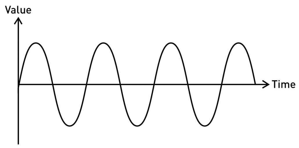
What are Analog Signals?
Analog signals are a type of continuous signals which are time-varying. Most of the environmental sensors such as temperature, light, pressure, and sound sensors communicate with microcontrollers using analog signals. These analog sensors output values in a specific range based on what the sensors are sensing. Analog signals normally take the form of sine waves and they can be defined by amplitude, frequency, and phase where amplitude denoting the highest height of the signals, frequency denoting the varying rate of the analog signals and phase denoting the position of the signal in time.
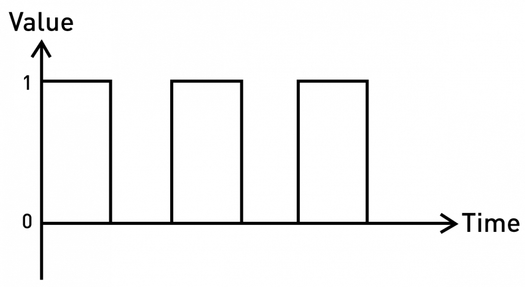
What are Digital Signals?
Digital signals are a type of discrete signals which are time-varying. The data is carried in the form of binary in a digital signal. This means it can either carry a “0” or a “1”. If you think about a switch, it sends out digital signals when pressing it to turn on while transmitting as a “1” and when pressed again to turn off while transmitting as a “0”. Digital signals also have an amplitude, frequency, and a phase just like analog signals. Digital Signals are normally defined by bit interval and bitrate where bit interval is the required time to transmit one bit and bitrate is the frequency of the bit interval.
What is an ADC?
When you need to use analog sensors and communicate with a microcontroller, it is not possible for the microcontroller to directly understand these analog signals because microcontrollers only understand digital signals which are formed by 1’s and 0’s. Therefore, this kind of system needs an intermediate device that could convert the analog signals from these sensors to digital signals in order for the microcontroller to understand these signals. An ADC (Analog to Digital Converter) is an electronic integrated circuit which is able to convert these analog signals to digital signals.
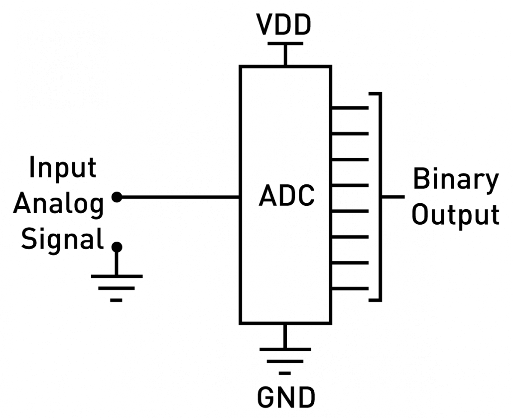
Normally an ADC would accept a range of voltage inputs and convert those into a form of binary numbers.
Arduino UNO already has an ADC?
Yes. Arduino already has an ADC with a resolution of 10-bit, which means it is able to identify 2^10 = 1024 discrete analog levels. However, this range is from 0 – 1023. Therefore. If you connect a sensor to an Arduino UNO and it outputs an analog level of 1023, the microcontroller will ultimately receive it as a 5V signal after going through the 10-bit ADC.
0 -> 0V
1023 -> 5V
But Why Do We Need an ADC?
Even though most microcontrollers have ADCs built into them, we sometimes need to connect additional ADC modules in order to get more accurate results from sensors in more advanced projects. There are different ADCs in the market such as 12-bit, 14-bit, 16-bit, 24-bit. The accuracy is directly related to the resolution of the ADC. When the resolution is higher, the accuracy becomes higher.
So, the number of discrete analog levels an ADC identifies can be expressed from the simple equation below
Number of discrete analog level = 2 ^ resolution of ADC
So, the Range of discrete analog levels in relation to the ADC resolution can be expressed by the following table.
| Resolution | Range |
|---|---|
| 24 | 16,777,216 |
| 16 | 65,536 |
| 14 | 16,384 |
| 12 | 4096 |
| 10 | 1024 |
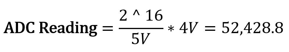
Now let’s look at a more general equation to obtain the ADC reading from the microcontroller.

For example, if you get an analog voltage of 4V on a 5V Arduino UNO while using a 16-bit ADC:
ADC Modules Offered by Seeed
We offer a range of ADC modules to use with your Arduino and Raspberry Pi in order to obtain more accurate results when working with your analog sensors.
Grove I2C ADC
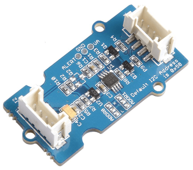
This is a 12-bit precision ADC module based on ADC121C021. It helps you increase the accuracy of value collected from analog sensors by providing a constant reference voltage. Because its address is changeable, you can use up to 9 I2C ADC at the same time at most. On the other hand, this module provides auto sleep function which lowers power consumption considerably.
Grove – 4 Channel 16-bit ADC (ADS1115) w/ Programmable Amplifier Gain
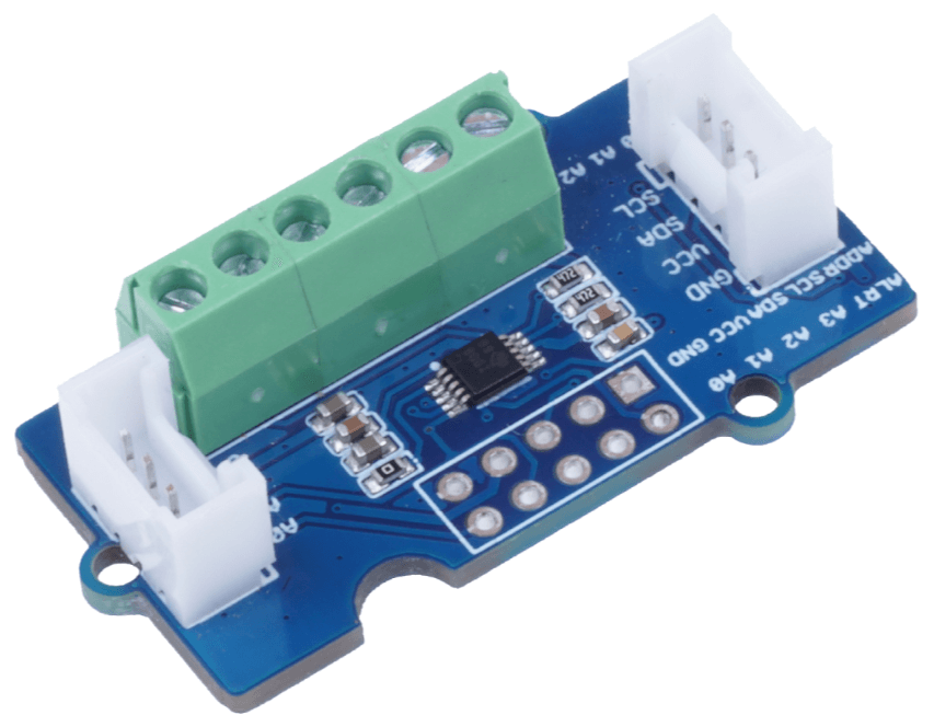
The ADS1115 is a 4-channel 16-bit high-resolution, low-power ADC chip with PGA (programmable gain amplifier) function. The PGA allows it to measure input voltages from ±256 mV to ±6.144 V, thus greatly expanding its application scenarios.
4-Channel 16-Bit ADC for Raspberry Pi (ADS1115)
This is a 4-channel 16-bit ADC for Raspberry Pi (ADS1115), based on Texas Instrument ADS1115, which is a high-precision, low-power, 16-bit ADC chip.
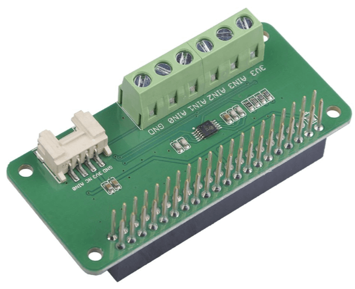
8-Channel 12-Bit ADC for Raspberry Pi (STM32F030)
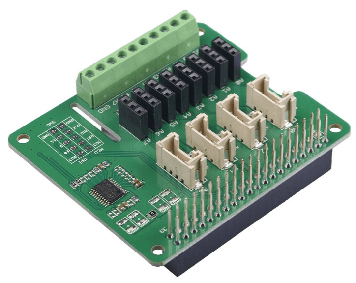
This is an 8-channel 12-bit ADC for Raspberry Pi (STM32F030), based on STM32F030 by ST, which is a high-precision, low-power, 12-bit ADC chip.
Grove – ADC for Load Cell (HX711)
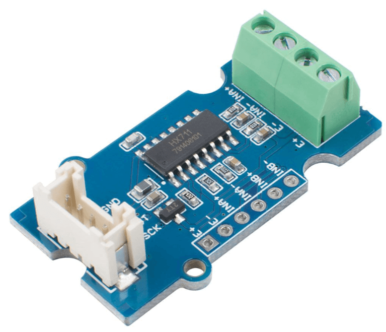
This is a 24-bit A/D converter designed specifically for the load cell. It contains an on-chip low noise programmable amplifier with an optional gain of 32, 64, and 128. The HX711 chip integrates a regulated power supply, an on-chip clock oscillator, and other peripheral circuits, which have the advantages of high integration, fast response, and strong anti-interference.
Play with Grove – 4 Channel 16-bit ADC(ADS1115) and Wio Terminal
Now let’s use the Grove – 4 Channel 16-bit ADC(ADS1115) with our Wio Terminal and see how it works.
Hardware Required
Step 1. Plug Grove – 16 Bit ADC(ADS1115) to the I2C port of Wio Terminal.
Step 2. Connect Wio Terminal to a PC via a USB cable.

Software
Step 1. Download the Seeed Arduino ADS1115 Library from Github.
Note
Follow Wio Terminal’s getting started before the following these steps.
Step 2. Download the example code here.
Step 3. Upload the demo. If you do not know how to upload the code, please check How to upload code.
Step 4. Adjust the rotary sensor and you will see the corresponding voltage values on Wio Terminal’s LCD screen:
Since this is a 16-bit ADC, the range of discrete analog values is 2^16 = 65536 and when you rotate the rotary angle sensor, the analog voltages are converted into digital voltages in the range 0 – 65535.
Conclusion
We hope you got a clear understanding of ADC and we hope you would incorporate an ADC in your next project in order to get accurate results from your analog sensors.