Influence of Gain Saturation Effect on Transverse Mode Instability Considering Four-Wave Mixing


College of Advanced Interdisciplinary Studies, National University of Defense Technology, Changsha 410073, China
*
Author to whom correspondence should be addressed.
Photonics 2022, 9(8), 577; https://doi.org/10.3390/photonics9080577
Submission received: 1 July 2022
/
Revised: 6 August 2022
/
Accepted: 8 August 2022
/
Published: 17 August 2022
(This article belongs to the Special Issue Rare Earth Doped Fiber Lasers)
Abstract
:Transverse mode instability (TMI) has been recognized as onse of the primary limiting factors for the average power scaling of high-brightness fiber lasers. In this work, a static model of the TMI effect based on stimulated thermal Rayleigh scattering (STRS) is established while considering the four-wave mixing (FWM) effect. The focus of the model is to theoretically investigate the TMI phenomenon and threshold power dominated by FWM. The gain saturation effect and fiber laser system parameters, such as seed power, pumping direction, and core numerical aperture, which have not been considered in the previous perturbation theory model, are also investigated. This work will enrich the perturbation theory model and extend its application scope in TMI mitigation strategies, providing guidance for understanding and suppressing TMI.
1. Introduction
Since the TMI phenomenon was first reported in 2010 [1], TMI has become one of the main limitations for the power scaling of high-brightness fiber lasers [2,3,4,5]. Although TMI does not directly restrict the power scaling, it will cause a sharp deterioration in beam quality and affect the stability of the laser system [6,7,8,9,10]. So far, much evidence has indicated that TMI may originate from STRS [11,12,13,14], according to which researchers have established various TMI static models based on STRS [12,15,16,17,18]. These models analyze the nonlinear coupling process between the fundamental mode and the higher-order modes to investigate the TMI characteristics under the assumption that the phase shift between the mode interference pattern and the refractive index grating is usually .
Compared with the above models, the perturbation theory model proposed by Zervas can not only obtain similar results as the TMI static model based on STRS [19], but also has a broader perspective for investigating the TMI phenomenon induced by four-wave mixing (FWM) [20]. The model indicates that high-power fiber laser systems will become more sensitive to small perturbations at high average powers, and that TMI is caused by FWM and cross-phase modulation (XPM) under certain conditions [20]. The influence of some factors in fiber laser systems on TMI, such as average gain, signal wavelength, and quantum defects, is also clearly shown using a succinct TMI threshold formula [21]. However, the model’s unique threshold definition and simplified temperature solution obscure many details of the physical processes underlying TMI, and it is unclear how some factors, such as gain saturation, seeding power, and pump direction, affect the TMI threshold, or whether the effects of the aforementioned factors in this model conform to other models [22,23,24,25,26,27,28,29]. Therefore, it is necessary to study these issues in order to better understand the TMI mechanism and mitigate the TMI effect in high-power fiber lasers.
In this work, a static model is established based on STRS and taking into consideration FWM. The model focuses on the theoretical study of the TMI phenomenon and threshold power dominated by FWM, where the connection between the FWM threshold and the TMI threshold is elucidated by analyzing the mode gain characteristics of the fiber amplifier. Moreover, the impact of gain saturation on the maximum the TMI threshold power of fiber amplifiers is investigated. Finally, some fiber laser system parameters, such as seed power, pumping direction, and core numerical aperture (NA), which were previously not considered in the perturbation theory model, are also investigated.
2. Theoretical Model
Some assumptions are made to simplify the model without loss of generality. Firstly, it is assumed that high-power fiber laser systems have only two modes (LP01 and LPmn). When the fiber laser system operates below or near the TMI threshold power and the seed is injected into the fiber amplifier with near-diffraction-limited beam, although the fiber may support multiple modes as the core radius increases, it can be ensured that the dynamic mode coupling only occurs between LP01 and LP11 modes due to the maximum nonlinear coupling gain of LP01 and LP11 modes [30]. Most TMI models make similar assumptions [18,31]. Secondly, the thermal lensing effect, which has no obvious effect on TMI induced by FWM in single core fiber amplifiers, is not considered.
Under the slow variation approximation in the time domain and space domain, the first order Helmholtz equation can be expressed as [32]
where is group velocity, is pump gain, is the propagation constant in vacuum, is the electric field, is the slow-varying amplitude, is the normalized transverse mode field distribution, is the propagation constant, and is the circular frequency. and represent LP01 and LPmn.
In high-power fiber laser systems, the temperature effect usually has a significantly greater influence on TMI than the Kramers–Kronig (KK) effect [15,19]. By neglecting the impact of the KK effect, the thermal nonlinear refractive index can be stated similarly to reference [23], as:
where is the thermal-optical coefficient, is the nonlinear refractive index coefficient, and temperature is expressed through heat conduction Equation (4) and boundary condition (5):
where , , and are fiber core density, specific heat capacity, and thermal conductivity, respectively, is the fiber thermal density, and is the convective coefficient. is the radius of the optical fiber cladding. If fulfills infinity, the boundary condition (5) can be simplified as follows because the refrigeration form has no significant effect on the TMI threshold [18].
By ignoring the background loss and photon darkening and assuming that quantum defect is the only source of heat in the fiber, the thermal density of the fiber amplifier can be expressed as:
where , the quantum defect coefficient , is the signal (pump) wavelength, is the transverse distribution of the fiber amplifier gain, is the small-signal gain, is the total concentration, () is the signal (pump) absorption (emission) cross-section, is the cladding area, is the pump power, .
Equations (3)–(11) are solved using the Green’s function method to obtain the nonlinear refractive index coefficient.
where is the second Bessel function of order , is the -th positive root of equation , .
According to the orthogonality of the modes, without considering the time domain variation, Equation (1) can be expressed as
where the first term on the right of Equations (13) and (14) is the pump gain, the second and third terms are SPM, the fourth term is XPM, and the last term is FWM. is the nonlinear coupling coefficient.
If , for simplification, XPM and FWM are ignored in Equation (13) and SPM is ignored in Equation (14), then the solution of Equations (13) and (14) is obtained.
where
and are the real and imaginary parts of . The first term of represents the influence of FWM on higher-order modes. The second term represents the gain of XPM on higher-order modes. The term is the pump gain. The output power of LPmn mode is expressed as:
3. Results and Discussions
According to Equations (16)–(20) in the above model, the nonlinear gain of higher-order modes and TMI threshold power in the fiber amplifier are simulated and calculated to explore the influence of FWM on TMI.
3.1. Nonlinear Gain of Higher-Order Modes
Most of the parameters used in the modeling are consistent to those used by Smith et al. [30], as listed in Table 1. Unlike reference [30], the fiber core is doped with a higher concentration of ytterbium ions, which has a higher thermal load and makes it easier to observe the effect of FWM in the fiber amplifier [33]. Incidentally, the concentration of ytterbium ions mentioned here can be achieved under current fiber fabrication technology. Thus, the fiber length is also shortened to 0.5 m.
Figure 1 shows the simulation results of the amplifier specified in Table 1, where the LP11 mode of the seed laser is evolved from the quantum noise [30]. Since TMI first occurs between the fundamental mode and the first higher-order mode (LP11) [34,35], it is assumed that the fiber only contains LP01 and LP11. The LP11 mode is seeded with 1 × 10⁻¹⁶ W [30]. The counter pump input power is 280 W, of which 0.17 W is not absorbed. The input LP01 power is 50 W and is amplified to 279 W in the output light.
Figure 1a shows the relationship between LP11 mode gain and frequency shift at different positions of the fiber amplifier. Figure 1b shows the gain curve at five specific positions of Figure 1a. When the fiber position Z moves from the seed input end to the pump end, the local gain gradually increases, and a sharp gain peak occurs at the fiber amplifier’s output end due to the function of FWM in Figure 1a. When Z ≤ 0.4 m, the maximizes local gain is still at the Stokes frequency shift of ~500 Hz, as shown in Figure 1b, which is the same as reference [30]. However, the LP11 mode with the small Stokes frequency shift obtains the maximum gain at the position of Z = 0.45 m (Stokes frequency shift is smaller than 100 Hz). The above result indicates that the effect of FWM can be ignored in the fiber amplifier when Z is less than 0.4 m.
The total gain of higher-order modes is shown in Figure 2, and the LP11 mode with a Stokes shift of ~90 Hz eventually has the maximum total gain (36.0) due to the FWM effect. However, the maximum local gain is still at the Stokes frequency shift of ~500 Hz at the position of Z < 0.4 m. Thus, we only focus on the LP11 mode with Stokes shifts of ~90 Hz and ~500 Hz. For simplification, it is assumed that all Stokes shift LP11 power is ~1 × 10⁻¹⁶ W in the seed. The output LP11 power with Stokes shift of ~90 Hz increases from 10−6 W (green dotted line) to 0.45 W (black solid curve) due to the FWM effect. It is obvious that the influence of FWM on the LP11 mode (90 Hz) becomes significant at the fiber length of 0.43 m, where the power of LP11 mode (90 Hz) quickly exceeds that of the LP11 mode (500 Hz) in Figure 2b. Therefore, the effect of FWM on higher-order modes cannot be negligible in the 80/250 μm fiber amplifier.
It is noted that when the signal power is 165 W, the LP11 mode with the same frequency as the LP01 mode begins to be affected by FWM. However, until the signal power reaches 280 W, the LP11 power is still far less than 5% of the output power, which is regarded as the threshold of TMI defined by some researchers [18,27,36]. If the TMI threshold is set at the signal optical power of 5% in the LP11 mode of the output light, the fiber amplifier still does not reach the trigger condition of TMI. Therefore, the FWM threshold cannot be completely equivalent to the TMI threshold.
3.2. The Threshold of TMI Affected by Gain Saturation
In high-power fiber amplifiers, it is difficult to obtain the general TMI threshold formula because of the variation of pump gain along the fiber. It is extremely unreasonable to calculate the TMI threshold induced by FWM using average gain [20]. Some assumptions need to be made in order to intuitively understand the influence of gain saturation on TMI and directly derive a more explicit TMI threshold formula. According to reference [37], when backward pump is applied and the seed power is comparable to the residual pump power, the connection between the pump power and the signal power can be simplified as follows:
Ignoring the amplified spontaneous emission and combining the Equations (9)–(11), the gain can be expressed as:
where is the effective mode field area of signal light and is positively proportional to .
According to reference [20], the TMI threshold power is defined when starts to be greater than 0. Thus, the TMI threshold can be obtained:
where represents the influence of phase matching required by FWM on the TMI threshold, and demonstrates the influence of refractive index grating intensity formed by thermal-optical effect in the fiber on TMI.
The relationship between and can be expressed by Equations (24) and (25) in step-index straight fiber [38]. is the transverse wave number. The cutoff wave number of LP01 and LP11 modes is 2.405 and 3.832, respectively. is inversely proportional to the square of the core radius.
Nonlinear coupling coefficient is incorporated along with Equations (12) and (15), and the relationship between and is obtained [12,22].
TMI threshold can be written as:
where is utilized to evaluate the gain saturation of high-power fiber amplifiers ( is often larger than 1). The effect of gain saturation on the TMI threshold is substantial if , and the larger the cladding area, the higher the TMI threshold [39]. As the core radius increases, the effective mode field area rises and the TMI threshold drops. The TMI threshold will rise as the signal emission cross-section increases and the pump absorption cross-section decreases [40,41]. For example, the TMI threshold of tandem pumping at 1018 nm is higher than laser diode pumping at 976 nm [21], and the TMI threshold rises with decreasing core radius [42].
The simulation results of Equation (26) are shown in Figure 3. According to reference [19], the normalized parameter V is 3, and the average gain of the fiber amplifier is 20 dB/m. Other parameters are listed in Table 1. As shown in Figure 3a, the effective mode field area grows and the threshold drops as the core radius increases. When V remains constant, is hardly affected by the core radius [12]. TMI threshold power will continue to decline as the core radius grows because is inversely proportional to the core radius and is also negatively correlated with the core radius. Two kinds of TMI thresholds are simulated in Figure 3b; the blue curve represents the result of Equation (27) in this paper, the black curve shows the TMI threshold of the well-saturated fiber amplifiers calculated by Zervas. In the well-saturated fiber amplifiers, is around 2. As shown in Figure 3b, when the core diameter is less than 40 μm, is substantially bigger than 2 and the gain saturation effect can significantly improve the TMI threshold which is inversely proportional to . The two kinds of TMI thresholds in Figure 3b are almost equal when the core diameter is larger than 70 μm, and gain saturation makes an insignificant contribution to TMI threshold increment. TMI threshold power is inversely proportional to due to the effect of and well saturation.
If only the influence of FWM on TMI is considered, the TMI threshold is indeed very high when the core is very small. However, the actual situation is that STRS is also an important factor affecting TMI in Figure 4b. When the core diameter is less than 50 μm, the STRS threshold is already smaller than the FWM threshold, and the TMI threshold will be dominated by the STRS threshold. If the actual situation is considered, STRS needs to be taken into account when the core is small, then the actual TMI threshold is not so high. Another work of ours has systematically studied the impact of both STRS and FWM on the TMI threshold [43].
This section illustrates how the pump gain, core/cladding radius, and wavelength of signal and pump affect the TMI threshold through the assumptions of backward pump and small signal input. The impacts of seed power, pumping direction, and core NA on the TMI threshold will then be investigated by numerical simulation.
3.3. Numerical Simulation Results of Other Fiber Laser System Parameters
Using backward pumping, a succinct TMI threshold formula was derived in the above section. The TMI threshold formula, however, could not be obtained directly for larger seed power and different pumping directions. Moreover, the influence of NA on TMI also needs to be considered. Therefore, in order to verify the effects of the seed power, pump directions, and core NA on the TMI threshold, the model in the second section is used for precise simulation calculations. The parameters for the 80/250 μm fiber amplifiers are listed in Table 1.
3.3.1. Forward Pumping with Different Seed Power
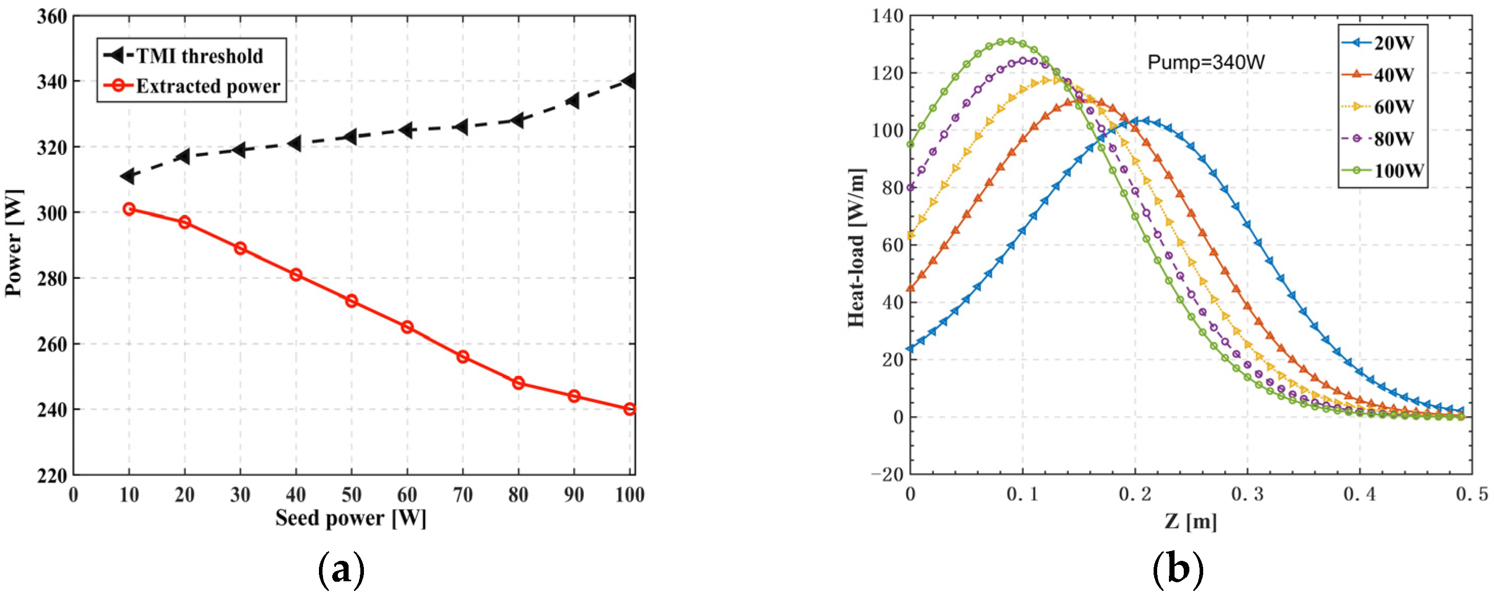
Forward pumping is a common pumping method in high-power fiber amplifier systems. The influence of seed power on TMI threshold in a forward pumped fiber amplifier is investigated, the results of which are shown in Figure 4. When the seed power is increased from 10 to 100 W, the TMI threshold only increases from 311 to 340 W, while the extracted power decrease from 301 to 240 W. The results differ from those in the prior simulation [27] due to the consideration of FWM. As shown in Figure 4b, the peak heat load of the forward pumping amplifier with the same pump power of 340 W continuously grows as the seed power increases from 20 to 100 W, and the gain of higher-order modes is positively associated with the peak heat load, resulting in a decrease in TMI threshold power. The choice of small signal seed will not significantly lower the TMI threshold for the forward pumped large core short fiber amplifiers.
3.3.2. Backward and Bidirectional Pumping with Different Seed Power
Previous research has demonstrated the influence of the gain saturation effect on the TMI threshold of fiber amplifiers with different pump direction and core diameters between 20 and 40 μm [25]. The influence of seed power on the TMI threshold is depicted in Figure 5 for the 80/250 μm backward and bidirectional pumped fiber amplifier, where the contribution of the gain saturation effect on TMI may be neglected. As shown in Figure 5a, when the seed power increases from 10 to 100 W in the backward pumping amplifier, the TMI threshold increases continually from 235 to 333 W, and the extracted power has no significant change, which is similar to a backward pumping amplifier that is not influenced by FWM [44]. As shown in the Figure 5b, with the continuous increase of seed power, the TMI threshold increases, and the extracted power firstly increases and then decreases for the bidirectional pumped fiber amplifiers with equally distributed forward and backward pump power. When the seed power is less than 80 W, only the fiber position near the output end meets the conditions of FWM excitation. When the seed power increases to more than 80 W, the position near the seed laser input also meets the conditions of FWM excitation, which will limit the growth of the TMI threshold and lead to the reduction of extracted power. The bidirectional pumped fiber amplifiers have a higher TMI threshold than the backward pumped fiber amplifiers, but the extracted power of the backward pumped fiber amplifier is less sensitive to the seed power.
3.3.3. Core Numerical Aperture
Core NA has a complex impact on TMI dominated by FWM according to Equation (27), and the nonlinear coupling coefficient and have a positive correlation with NA in Figure 6a. The growth of is very tiny compared to that of when NA increases from 0.04 to 0.07, which is consistent with reference [45], hence the TMI output threshold power will rise from 306 to 336 W in Figure 6b. It is advantageous to boost NA properly for large core short fiber amplifiers, such as the 80/250 μm forward pumping amplifier in this paper, where the influence of on TMI is more significant compared with .
4. Conclusions
The gain amplification process of higher-order modes in fiber laser is demonstrated in this work using the TMI numerical simulation model incorporating FWM. When the gain saturation effect is taken into account, the TMI threshold of the fiber amplifier is initially inversely proportional to the fourth power of the core radius, and finally inversely proportional to the square of the core radius as the mode area increases. The influence of FWM on the TMI threshold is investigated for the large core short fiber, i.e., 80/250 μm, by taking account of the pumping direction, seed power, and core NA. It was discovered that the backward pumping amplifier’s pumping threshold practically remained constant, whereas the forward pumping amplifier’s pumping threshold fell linearly with the rise in seed power. The larger the core NA, the greater the difference in mode wave vectors and the higher the TMI threshold. This work could help gain a better understanding of TMI from a new perspective and would further contribute to TMI mitigation in high-power fiber lasers.
Author Contributions
Methodology: L.H.; validation: L.H.; investigation: H.L., L.H., H.W. and Z.P.; writing—original draft preparation: H.L.; writing—review and editing: L.H., H.W. and P.Z.; supervision: L.H.; project administration: P.Z.; funding acquisition: P.Z. All authors have read and agreed to the published version of the manuscript.
Funding
This research was funded by the National Natural Science Foundation of China (62061136013, 62035015) and the Natural Science Foundation of Hunan province, China (2019JJ10005).
Institutional Review Board Statement
Not applicable.
Informed Consent Statement
Not applicable.
Data Availability Statement
The data that support the findings of this study are available from the authors upon reasonable request.
Acknowledgments
The authors would like to thank Yi An and Xiao Chen for inspiring discussions.
Conflicts of Interest
The authors declare no conflict of interest.
References
- Eidam, T.; Hanf, S.; Seise, E.; Andersen, T.V.; Gabler, T.; Wirth, C.; Schreiber, T.; Limpert, J.; Tünnermann, A. Femtosecond fiber CPA system emitting 830 W average output power. Opt. Lett. 2010, 35, 94–96. [Google Scholar] [CrossRef]
- Jauregui, C.; Stihler, C.; Limpert, J. Transverse mode instability. Adv. Opt. Photonics 2020, 12, 429–484. [Google Scholar] [CrossRef]
- Stihler, C.; Jauregui, C.; Kholaif, S.E.; Limpert, J. Intensity noise as a driver for transverse mode instability in fiber amplifiers. PhotoniX 2020, 1, 8. [Google Scholar] [CrossRef]
- Ballato, J.; Otto, H.-J.; Jauregui, C.; Limpert, J.; Tünnermann, A. Average power limit of fiber-laser systems with nearly diffraction-limited beam quality. In Proceedings of the Fiber Lasers XIII: Technology, Systems, and Applications, San Francisco, CA, USA, 9 March 2016. [Google Scholar]
- Ren, S.; Lai, W.; Wang, G.; Li, W.; Song, J.; Chen, Y.; Ma, P.; Liu, W.; Zhou, P. Experimental study on the impact of signal bandwidth on the transverse mode instability threshold of fiber amplifiers. Opt. Express 2022, 30, 7845–7853. [Google Scholar] [CrossRef]
- Li, Z.; Huang, Z.; Xiang, X.; Liang, X.; Lin, H.; Xu, S.; Yang, Z.; Wang, J.; Jing, F. Experimental demonstration of transverse mode instability enhancement by a counter-pumped scheme in a 2 kW all-fiberized laser. Photonics Res. 2017, 5, 77–81. [Google Scholar] [CrossRef]
- Lupi, J.F.; Johansen, M.M.; Michieletto, M.; Laegsgaard, J. Static and dynamic mode coupling in a double-pass rod-type fiber amplifier. Opt. Lett 2018, 43, 5535–5538. [Google Scholar] [CrossRef]
- Cao, R.; Chen, G.; Chen, Y.; Zhang, Z.; Lin, X.; Dai, B.; Yang, L.; Li, J. Effective suppression of the photodarkening effect in high-power Yb-doped fiber amplifiers by H2 loading. Photonics Res. 2020, 8, 288–295. [Google Scholar] [CrossRef]
- Ye, Y.; Lin, X.; Xi, X.; Shi, C.; Yang, B.; Zhang, H.; Wang, X.; Li, J.; Xu, X. Novel constant-cladding tapered-core ytterbium-doped fiber for high-power fiber laser oscillator. High Power Laser Sci. Eng. 2021, 9, e21. [Google Scholar] [CrossRef]
- Pulford, B.; Holten, R.; Matniyaz, T.; Kalichevsky-Dong, M.T.; Hawkins, T.W.; Dong, L. kW-level monolithic single-mode narrow-linewidth all-solid photonic bandgap fiber amplifier. Opt. Lett. 2021, 46, 4458–4461. [Google Scholar] [CrossRef]
- Jauregui, C.; Eidam, T.; Otto, H.-J.; Stutzki, F.; Jansen, F.; Limpert, J.; Tuennermann, A. Physical origin of mode instabilities in high-power fiber laser systems. Opt. Express 2012, 20, 12912–12925. [Google Scholar] [CrossRef]
- Dong, L. Stimulated thermal Rayleigh scattering in optical fibers. Opt. Express 2013, 21, 2642–2656. [Google Scholar] [CrossRef]
- Smith, A.V.; Smith, J.J. Overview of a Steady-Periodic Model of Modal Instability in Fiber Amplifiers. IEEE J. Sel. Top. Quantum Electron. 2014, 20, 472–483. [Google Scholar] [CrossRef]
- Kong, F.; Xue, J.; Stolen, R.H.; Dong, L. Direct experimental observation of stimulated thermal Rayleigh scattering with polarization modes in a fiber amplifier. Optica 2016, 3, 975–978. [Google Scholar] [CrossRef]
- Smith, A.V.; Smith, J.J. Mode instability in high power fiber amplifiers. Opt. Express 2011, 19, 10180–10192. [Google Scholar] [CrossRef]
- Ward, B.; Robin, C.; Dajani, I. Origin of thermal modal instabilities in large mode area fiber amplifiers. Opt. Express 2012, 20, 11407. [Google Scholar] [CrossRef]
- Tao, R.; Zhou, P.; Ma, P.; Wang, X.; Liu, Z. Study of Wavelength Dependence of Mode Instability Based on a Semi-Analytical Model. IEEE J. Quantum Electron. A Publ. IEEE Quantum Electron. Appl. Soc. 2015, 51, 1–6. [Google Scholar]
- Hansen, K.R.; Alkeskjold, T.T.; Broeng, J.; Lægsgaard, J. Theoretical analysis of mode instability in high-power fiber amplifiers. Opt. Express 2013, 21, 1944–1971. [Google Scholar] [CrossRef]
- Zervas, M.N. Transverse mode instability analysis in fiber amplifiers. In Proceedings of the Fiber Lasers XIV: Technology and Systems, San Francisco, CA, USA, 17 March 2017. [Google Scholar]
- Zervas, M.N. Modal instability in two-mode optical fiber amplifiers. In Proceedings of the Fiber Lasers XVIII: Technology and Systems, Online Only, 7 March 2021. [Google Scholar]
- Zervas, M.N. Transverse mode instability, thermal lensing and power scaling in Yb3+-doped high-power fiber amplifiers. Opt. Express 2019, 27, 19019–19041. [Google Scholar] [CrossRef]
- Dong, L. Accurate Modeling of Transverse Mode Instability in Fiber Amplifiers. J. Lightwave Technol. 2022, 40, 4795–4803. [Google Scholar] [CrossRef]
- Tao, R.; Wang, X.; Zhou, P. Comprehensive Theoretical Study of Mode Instability in High-Power Fiber Lasers by Employing a Universal Model and Its Implications. IEEE J. Sel. Top. Quantum Electron. 2018, 24, 1–19. [Google Scholar] [CrossRef]
- Smith, A.V.; Smith, J.J. Increasing mode instability thresholds of fiber amplifiers by gain saturation. Opt. Express 2013, 21, 15168–15182. [Google Scholar] [CrossRef]
- Tao, R.; Ma, P.; Wang, X.; Zhou, P.; Liu, Z. Theoretical study of pump power distribution on modal instabilities in high power fiber amplifiers. Laser Phys. Lett. 2017, 14, 025002. [Google Scholar] [CrossRef]
- Hansen, K.R.; Laegsgaard, J. Impact of gain saturation on the mode instability threshold in high-power fiber amplifiers. Opt. Express 2014, 22, 11267–11278. [Google Scholar] [CrossRef] [PubMed]
- Tao, R.; Wang, X.; Zhou, P.; Liu, Z. Seed power dependence of mode instabilities in high-power fiber amplifiers. J. Opt. 2017, 19, 065202. [Google Scholar] [CrossRef]
- Tao, R.; Ma, P.; Wang, X.; Zhou, P.; Liu, Z. Mitigating of modal instabilities in linearly-polarized fiber amplifiers by shifting pump wavelength. J. Opt. 2015, 17, 045504. [Google Scholar] [CrossRef]
- Naderi, S.; Dajani, I.; Madden, T.; Robin, C. Investigations of modal instabilities in fiber amplifiers through detailed numerical simulations. Opt. Express 2013, 21, 16111–16129. [Google Scholar] [CrossRef] [PubMed]
- Smith, A.V.; Smith, J.J. Influence of pump and seed modulation on the mode instability thresholds of fiber amplifiers. Opt. Express 2012, 20, 24545–24558. [Google Scholar] [CrossRef] [PubMed]
- Hendow, S.T.; Hu, I.N.; Zhu, C.; Zhang, C.; Thomas, A.; Galvanauskas, A. Analytical time-dependent theory of thermally induced modal instabilities in high power fiber amplifiers. In Proceedings of the Fiber Lasers X: Technology, Systems, and Applications, San Francisco, CA, USA, 22 March 2013. [Google Scholar]
- Agrawal, G.P. Nonlinear Fiber Optics, 5th ed.; Academic Press: Boston, MA, USA, 2013; pp. 45–47. [Google Scholar]
- Zervas, M.N. Transverse-modal-instability gain in high power fiber amplifiers: Effect of the perturbation relative phase. APL Photonics 2019, 4, 022802. [Google Scholar] [CrossRef]
- Huang, L.; Yao, T.; Leng, J.; Guo, S.; Tao, R.; Zhou, P.; Cheng, X. Mode instability dynamics in high-power low-numerical-aperture step-index fiber amplifier. Appl. Opt. 2017, 56, 5412–5417. [Google Scholar] [CrossRef]
- Otto, H.-J.; Stutzki, F.; Jansen, F.; Eidam, T.; Jauregui, C.; Limpert, J.; Tünnermann, A. Temporal dynamics of mode instabilities in highpower fiber lasers and amplifiers(Article). Opt. Express 2012, 20, 15710–15722. [Google Scholar] [CrossRef] [PubMed]
- Smith, A.V.; Smith, J.J. Maximizing the mode instability threshold of a fiber amplifier. arXiv 2013, arXiv:Physics/1301.3489. [Google Scholar] [CrossRef]
- Ward, B.G. Maximizing power output from continuous-wave single-frequency fiber amplifiers. Opt. Lett. 2015, 40, 542–545. [Google Scholar] [CrossRef] [PubMed]
- Snyder, A.W. Asymptotic Expressions for Eigenfunctions and Eigenvalues of a Dielectric or Optical Waveguide. IEEE Trans. Microw. Theory Tech. 1969, 17, 1130–1138. [Google Scholar] [CrossRef]
- Smith, A.V.; Smith, J.J. Raising the mode instability thresholds of fiber amplifiers. In Proceedings of the Fiber Lasers XI: Technology, Systems, and Applications, San Francisco, CA, USA, 7 March 2014. [Google Scholar]
- Li, R.; Wu, H.; Xiao, H.; Leng, J.; Zhou, P. More than 5 kW counter tandem pumped fiber amplifier with near single-mode beam quality. Opt. Laser Technol. 2022, 153, 108204. [Google Scholar] [CrossRef]
- Wu, H.; Li, R.; Xiao, H.; Huang, L.; Yang, H.; Leng, J.; Pan, Z.; Zhou, P. First demonstration of a bidirectional tandem-pumped high-brightness 8 kW level confined-doped fiber amplifier. J. Lightwave Technol. 2022, 40, 5673–5681. [Google Scholar] [CrossRef]
- Leidner, J.P.; Marciante, J.R. Three fiber designs for mitigating thermal mode instability in high-power fiber amplifiers. Opt. Express 2020, 28, 28502–28517. [Google Scholar] [CrossRef]
- Li, H.; Huang, L.; Wu, H.; Chen, Y.; Pan, Z.; Zhou, P. Threshold of transverse mode instability considering four-wave mixing. Opt. Express 2022. [Google Scholar] [CrossRef]
- Roohforouz, A.; Eyni Chenar, R.; Rezaei-Nasirabad, R.; Azizi, S.; Hejaz, K.; Hamedani Golshan, A.; Abedinajafi, A.; Vatani, V.; Nabavi, S.H. The effect of population inversion saturation on the transverse mode instability threshold in high power fiber laser oscillators. Sci. Rep. 2021, 11, 21116. [Google Scholar] [CrossRef] [PubMed]
- Tao, R.; Ma, P.; Wang, X.; Zhou, P.; Liu, Z. Influence of core NA on thermal-induced mode instabilities in high power fiber amplifiers. Laser Phys. Lett. 2015, 12, 085101. [Google Scholar] [CrossRef]
Figure 1.
(a) The local gain as a function of frequency shift and fiber length, (b) the gain at different position of fiber of 0.1, 0.2, 0.3, 0.4, and 0.45 m.
Figure 1.
(a) The local gain as a function of frequency shift and fiber length, (b) the gain at different position of fiber of 0.1, 0.2, 0.3, 0.4, and 0.45 m.

Figure 2.
(a) The total gain and (b) different mode power in the 80/250 μm fiber amplifier.

Figure 3.
TMI threshold power (given by Equation (27)) and effective mode field area (a) as a function of core diameter, and (b) the TMI threshold in this work is compared with the reference [19].
Figure 3.
TMI threshold power (given by Equation (27)) and effective mode field area (a) as a function of core diameter, and (b) the TMI threshold in this work is compared with the reference [19].

Figure 4.
(a) Relationship between TMI threshold and seed power of the forward pumped 80/250 μm fiber amplifier, and (b) the heat load of fiber amplifiers with different seed power.
Figure 4.
(a) Relationship between TMI threshold and seed power of the forward pumped 80/250 μm fiber amplifier, and (b) the heat load of fiber amplifiers with different seed power.

Figure 5.
The TMI threshold and extracted power in (a) backward and (b) bidirectional pumped fiber amplifiers.
Figure 5.
The TMI threshold and extracted power in (a) backward and (b) bidirectional pumped fiber amplifiers.

Figure 6.
Relationship between NA and (a) wave vector difference between the fundamental mode and higher-order modes and , (b) the TMI threshold.
Figure 6.
Relationship between NA and (a) wave vector difference between the fundamental mode and higher-order modes and , (b) the TMI threshold.


Table 1.
The simulation parameters of fiber amplifiers.
| Parameter | Value | Parameter | Value |
|---|---|---|---|
| 40 μm | 125 μm | ||
| 976 nm | 1064 nm | ||
| m2 | |||
| m2 | m2 | ||
| 1.451 | 1.45 | ||
| L | 500 mm | ||
| 901 μs | m−3 | ||
| 1.38 W/K | J/(m3·K) |
Publisher’s Note: MDPI stays neutral with regard to jurisdictional claims in published maps and institutional affiliations. |
© 2022 by the authors. Licensee MDPI, Basel, Switzerland. This article is an open access article distributed under the terms and conditions of the Creative Commons Attribution (CC BY) license (https://creativecommons.org/licenses/by/4.0/).
Share and Cite
MDPI and ACS Style
Li, H.; Huang, L.; Wu, H.; Pan, Z.; Zhou, P. Influence of Gain Saturation Effect on Transverse Mode Instability Considering Four-Wave Mixing. Photonics 2022, 9, 577. https://doi.org/10.3390/photonics9080577
AMA Style
Li H, Huang L, Wu H, Pan Z, Zhou P. Influence of Gain Saturation Effect on Transverse Mode Instability Considering Four-Wave Mixing. Photonics. 2022; 9(8):577. https://doi.org/10.3390/photonics9080577
Chicago/Turabian StyleLi, Haobo, Liangjin Huang, Hanshuo Wu, Zhiyong Pan, and Pu Zhou. 2022. "Influence of Gain Saturation Effect on Transverse Mode Instability Considering Four-Wave Mixing" Photonics 9, no. 8: 577. https://doi.org/10.3390/photonics9080577
Note that from the first issue of 2016, this journal uses article numbers instead of page numbers. See further details here.