

A Misalignment-Insensitive Hybrid IPT System with Constant Current Output Based on Parameter Optimization
1
School of Electrical Engineering, Xi’an University of Technology, 58, Yanxiang Rd., Xi’an 710054, China
2
School of Electronic Information Engineering, Xi’an Technological University, 2, Xuefu Rd., Xi’an 710021, China
*
Author to whom correspondence should be addressed.
Electronics 2023, 12(5), 1138; https://doi.org/10.3390/electronics12051138
Submission received: 28 January 2023
/
Revised: 20 February 2023
/
Accepted: 24 February 2023
/
Published: 26 February 2023
(This article belongs to the Special Issue Future Development in Wireless Power Transfer Technology for Internet of Things (IoT) in Smart Grid)
Abstract
:High misalignment-insensitive capacity is of great importance for inductive power transfer (IPT) systems. A hybrid topology based on a parameter optimization design method is presented to obtain constant current output regardless of the coupling and load. DDQ coils are employed to protect against system key parameter changes, and a particle swarm optimization (PSO) method has been presented to achieve a nearly constant current output without using complex control schemes. A hybrid IPT system using DDQ coils has been built. The experimental results verify that the current fluctuation is within 5% when the load varies from 5 Ω to 10 Ω within 50% misalignment of the coupling pads. Moreover, the maximum system DC–DC efficiency is up to 91%.
1. Introduction
Inductive power transfer technology (IPT) utilizes the high-frequency electromagnetic field to transfer power, which has superior advantages compared with conventional conductive charging system, such as reliability, safety, convenience [1,2], etc. Hence, IPT technology has a wide application prospect, such as underwater equipment, unmanned aerial vehicles (UAVs) [3], implantable medical devices [4], electric vehicles (EVs) [5], and automatic guided vehicles (AGVs) [6].
For EV applications, the primary and pick-up coils dramatically vary, which may cause the coupling fluctuation, the output power fluctuation, and efficiency reduction [7,8,9,10,11]. Many closed-loop control schemes have been presented to mitigate these issues. An additional dc–dc converter is one of the popular methods to maintain the output power under misalignment conditions. For a dynamic EV charging application, a cascade dc–dc converter is added at secondary side of the IPT system to deliver a power of 15 kW to an EV charger, which can operate along the direction of travel within the lateral misalignment of ±200 mm. However, this method needs double receivers and complex control strategies [12]. In addition, a cascade buck-boost converter is also added at the secondary side of the IPT system to achieve maximum efficiency tracking against coupling and load variation [13]. However, the above-mentioned cascade dc–dc converter may cause extra volume and cost. In addition, pulse frequency modulation (PFM) and phase-shift modulation can also be adopted to provide the stable output power against misalignment [14,15,16]. In order to achieve stable output with wide misalignment, pulse frequency modulation is used in the primary inverter to regulate the output voltage of the load [14]. However, this method needs the help of wireless communication, which may cause bifurcation phenomena when the couplings vary dramatically. Moreover, this method can only realize stable output for single load. In order to meet the demand for multi-loads, both the pulse frequency modulation and phase-shift modulation are adopted to maintain stable output power under multi-load conditions [15]. However, all above-mentioned control schemes usually need the additional help of wireless communications to get the current or voltage of the load and then regulate the inverter at the primary side, which may reduce system dynamic response and cause instability issues.
Hence, in order to improve the system performance without additional cascade dc–dc converter, closed-loop control schemes and RF wireless communication, optimization in WPT compensation topology and parameters has been proposed to improve the power output stability [17,18,19,20,21]. A design method of primary T-type topology is presented to mitigate the output power fluctuation, which contains the considerations of soft switching and system efficiency. This method can achieve stable output voltage under large misalignment, which is up to 200% coupling variation [17]. In [18], a reformed LCC–LCC topology based on dual-coupled coils is presented to improve misalignment tolerance. However, this reformed LCC–LCC topology can only provide 56.8% and 82.6% of the well aligned position, which means the output power fluctuation is still a little larger. In addition, the reconfigurable compensation topology is proposed to limit transmission power fluctuation within 5% when the coupling coefficient ranges from 0.1 to 0.25 [19]. However, this reconfigurable compensation topology can only realize relatively constant power output and ignore the load-independent characteristics, which is the real demand for many applications. In [20], a dual-side detuned series–series (SS) topology is proposed to limit the output power drop within 20%, when the coupling coefficient ranges from 0.08 to 0.2. An optimized LCC compensation topology is presented to realize robust reaction to large coupling variations [21] when the coupling coefficient ranges from 0.18 to 0.32. However, the above-mentioned approaches based on parameter optimization usually cannot achieve load-independent output, which may limit the practical applications.
Apart from the proposed control schemes and topology parameter optimization, some investigations try to solve the issues by designing novel magnetic couplers. Double-D coils [22], tripolar coils [23], quadruple-D coils [24],unsymmetrical coils [25], and series solenoid and DD coils [26] have been presented to provide a relatively uniform magnetic distribution under misalignment conditions. Moreover, some investigations try to maintain stable output power by designing hybrid topologies with opposite output trends [27,28,29,30]. A hybrid IPT system combining with LCC topology and SS topology is presented to achieve smoothly output current fluctuation against coupling variation [27,28]. Moreover, a reconfigurable hybrid topology with a T-type is proposed to maintain relatively constant voltage and current output [30]. However, this method needs many resonant components and switches, which may cause an increase in volume and cost. Additionally, the output current of the inverter will increase dramatically when the secondary side is removed, which may lead the instability and insecurity factor. Although the mentioned above hybrid topologies can achieve stable output, the above-mentioned approaches ignore the effect of parasitic parameters on system output, and the simple and efficient parameter optimization design method is still missing.
In this article, a hybrid topology based on parameter optimization design method is proposed to achieve stable output under the pad misalignment conditions, and the main contributions are as follows.
- (1)
- The hybrid topology model with parasitic impedance is established, and the influence of parasitic impedance on system output is summarized and analyzed. In addition, the proposed hybrid topology can safely operate without secondary side, which utilizes the characteristics of the circuit without additional control schemes.
- (2)
- The DDQ coils are adopted in this system, which can eliminate the influence of the cross coupling on system output. The PSO parameter optimization design method is proposed to maintain constant output against coupling variation, which can effectively simplify the complexity of the system design.
The rest of this paper is organized as follows. Section 2 introduces the hybrid topology containing parasitic impedance and the detailed theoretical analysis. In Section 3, the mutual inductance characteristic of the DD2Q pads is summarized, and the PSO parameter optimization design method is given. In Section 4, the rationality and effectiveness of the system are experimentally validated. Finally, Section 5 concludes this article.
2. Theoretical Analysis
The hybrid topology containing parasitic impedance is shown in Figure 1, which consists of LCC–LCC topology and SS topology. L1, L3 and L2, L4 are the primary and secondary self-inductances of the DDQ coupling pad. M12, M34 are the main couplings, and M13, M14 and M23, M24 are the cross couplings. R1, R2, R3, and R4 are parasitic resistances of the DDQ coupling coil, respectively. In addition, R0, R5 are parasitic resistances of the resonant inductors. The hybrid topology is supplied by dc voltage E with high frequency inverter. Q1–Q4 constitutes the high frequency inverter, and the system operates at a fixed frequency ω and duty cycle. Uout and Iout are the output voltage and the output current of the inverter, respectively. D1–D4 constitutes the high rectifier circuit, CL is the filter capacitor. I3 is the input AC current before rectification, and IL is the load current.
In order to reduce the size and weight of the system, L0 (L5) and C3 (C4) at the primary side and secondary side can be combined as one passive component, which can be expressed by
the relationship between the equivalent load RAB and the load RL can be given by [7]
the hybrid IPT system is completely resonant, the resonant angular ω satisfies the following relations,
according to Figure 1, the KVL and KCL equations between the voltages and currents can be described as
therefore, by solving (4), we can obtain the output current I0 of the inverter, the output current I1 of the L1 coil, the output current I2 of the L2 coil and the output current I3 of the system,
from (5), the output current I0 of the inverter, the output current I1 of the L1 coil, the output current I2 of the L2 coil, and the output current I3 of the system all are related with the parasitic resistance (R0~R5). Additionally, the output current expression is relatively complicated, therefore, it is difficult to analyze the influence of parasitic resistance (R0~R5) on the output of the system. For simplifying the analysis, the parasitic resistances of self-induction (L1, L2, L3 and L4) of DDQ coils are assumed equal, and the parasitic resistances of compensation inductors L0 and L5 are assumed equal, thus we can obtain
where a and b are coefficients.
Then, according to (6), we can get the simplified expression of (5), which can be deduced as,
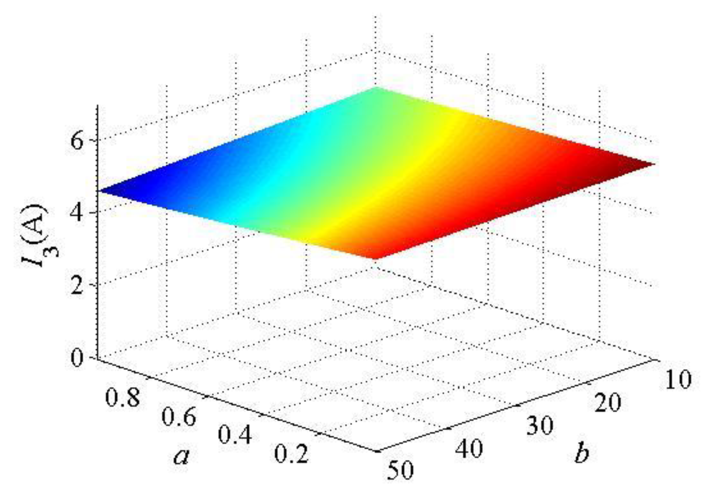
Figure 2 shows the output current of the hybrid topology containing parasitic impedance when assuming R1 = 0.5 Ω, a = [0.01, 1], b = [100, 200]. Evidently, the output current I3 drops when the coefficient a rises gradually, which indicates that the parasitic resistance affects the output current. Additionally, the output current I3 also drops when the coefficient b rises gradually, which indicates that the load resistance affects the output current. In the actual design process, we can use high frequency Litz wire with very low parasitic impedance to reduce the influence of parasitic impedance on the output current of the IPT system. Moreover, it can be concluded that the output current I3 gradually drops as the system load increases due to the existence of parasitic resistances.
In addition, according to (7), we can get the efficiency of the system,
Figure 3 shows the efficiency of the hybrid topology containing parasitic impedance. It is evident that the system efficiency shows a trend in convex function when the coefficient a rises gradually, which indicates that the parasitic resistance affects the output efficiency. Additionally, the output efficiency drops when the coefficient b rises gradually, which indicates that the load resistance affects the output current. Moreover, the compensation element with parasitic impedance has less influence on the output efficiency than the load.
In practical applications, parasitic impedance is usually small enough to be ignored. Therefore, the parasitic resistance of the coupling coil and the compensated inductor is assuming R0 = R1 = R2 = R3 = R4 = R5 = 0. By solving (4), the output current I0 of the inverter, the output current I1 of the L1 coil, the output current I2 of the L2 coil, and the output current I3 of the system can be expressed as,
thus, according to the output current I0 of the inverter in (9), the total input equivalent impedance of the IPT system can be derived by
from (9) and (10), the total input impedance is pure resistant, which can help to improve overall transmission efficiency. In addition, when the coupling coil misalignment occurs, the M12 and M34 may decrease simultaneously. Thus, the system can achieve stable output through optimizing the compensation parameters L0 and L5.
3. Magnetic Coupler Design Additionally, Parametric Design
3.1. Magnetic Coupler Design
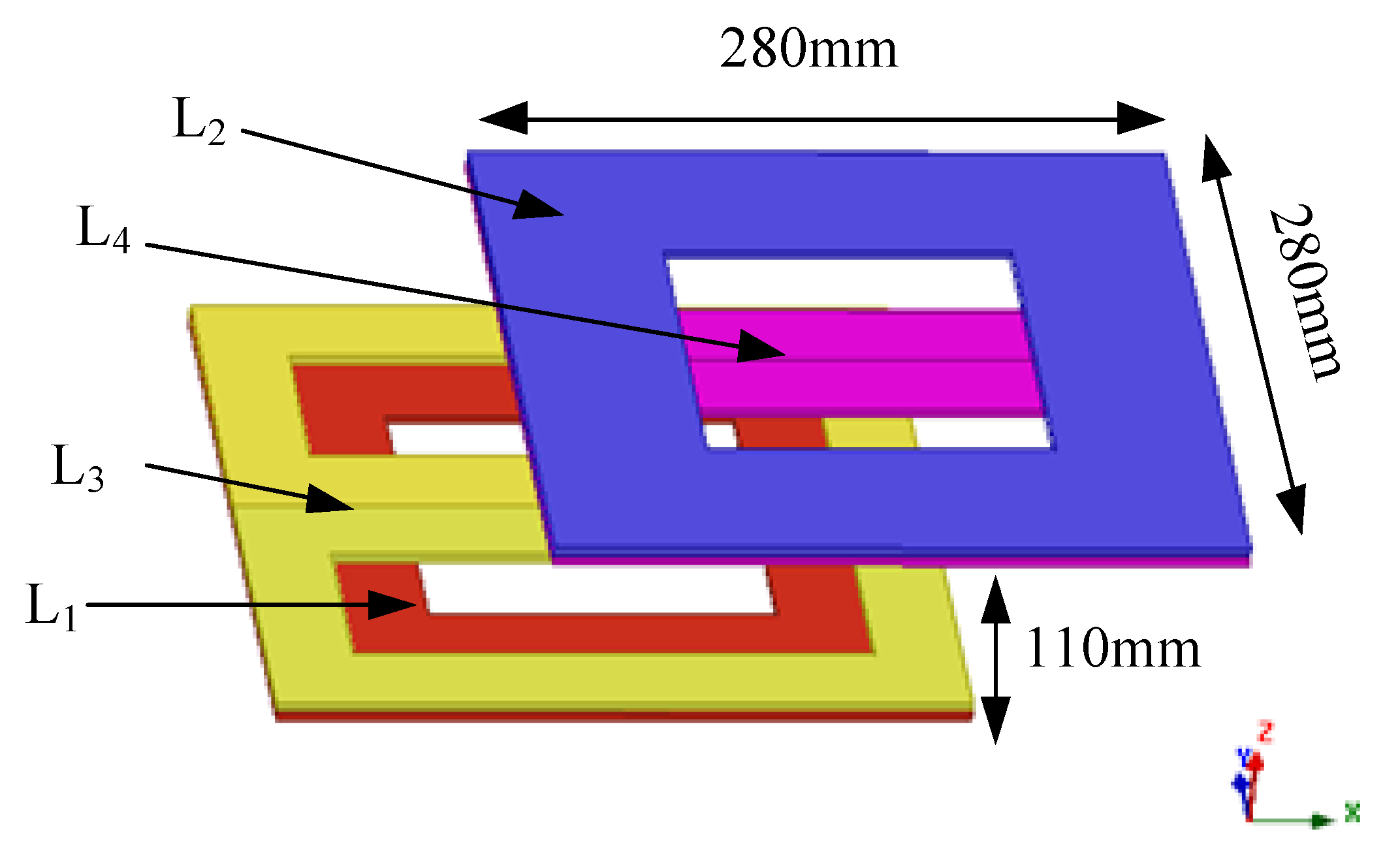
The DDQ pads and DD pads have been presented in [27,29], which are used to maintain stable power output against misalignment. Therefore, the DDQ magnetic coupler is adopted [2], as shown in Figure 4. All the self-inductances and the mutual inductances are measured along the X-, Y-, and Z-axis, as shown in Figure 5. The self-inductances almost remain constant when the misalignment occurs, as shown in Figure 5a, which illustrates that the pad misalignment cannot affect the self- inductance of the DDQ pad. In addition, only the main mutual inductances change apparently when the X-axis misalignment occurs, and the cross mutual inductances are small enough to be ignored in Figure 5b. Moreover, M12 and M34 have almost the same variation trend, which means that they have a linear trend. However, the M12, M34, M14, and M23 change dramatically in Figure 5c. In practice, when Y-axis misalignment occurs, auxiliary equipment can be used to adjust parameters such as the car reversing image or reversing radar. In Figure 5d, we can clearly find only the main mutual inductances change apparently when the Z-axis misalignment occurs, and the cross mutual inductances are also small enough to be neglected. However, the Z-axis misalignment rarely appeared in practical applications. Thus, this paper focuses on the analysis of X-axis misalignment.
3.2. Parametric Design Method
Particle Swarm Optimization (PSO) is a computational method with evolutionary characteristics. It originates from complex adaptive systems. Additionally, it mainly studies the phenomenon that adaptive subjects learn from the interaction between the environment and other subjects, as to change their own structure or behavior. The basic idea behind PSO is based on one of the most common population system birds, and the algorithm is based on the foraging behavior of birds. Each bird in the flock forages randomly in a large and fixed area, which does not know the exact location of the target and the food, but it can know the distance between its current location and the final target. Additionally, then the flocks of birds can exchange information by calling or marking, so that the bird closest to the food is identified by comparison, and more birds flock in that direction to find the food.
In the PSO, the whole optimization problem is the process of birds looking for food, and each bird flying in the air looking for food is the basic search unit of the algorithm: particles. In other words, particle swarm optimization is the process of a group of particles looking for all the solutions in the feasible domain. Each particle has five ever-changing properties: its current position, its own best position, the group’s best position, its current velocity, and its current velocity. Where the current position refers to each particle in this iteration, the position of the latter is represented by the adaptive value in the algorithm. The optimal position of a particle is the position closest to the solution reached in the past, the optimal position of the group is the position of the particle closest to the solution among all particles, and the current speed is the step size of each iteration of the particle adjusted according to the above three data. Through the iterative changes of these four attributes, the basic steps of particle swarm optimization algorithm are formed: firstly, a certain number of particles are randomly initialized, and the optimal solution of the problem is found through iteration at each time. After the iteration, each particle updates its position and compares the current position with the group optimal position to determine whether it is a new position closer to the optimal solution. At the same time, all particles update the speed of the next iteration according to the new optimal position of the population and the current position after each iteration.
As shown in Figure 6, the running process of the algorithm is as follows:
- (1)
- Generate a certain number of particles randomly in the feasible domain, and each particle has a random position and random initial velocity. Additionally, define a population optimal position and initialize it to 0.
- (2)
- Select the particle with the best position from all the particles and save its position information into the best position of the group.
- (3)
- Perform iteration, and the particle updates the new position after iteration according to its current position and speed.
- (4)
- Each particle updates the speed of the next iteration according to the current optimal position of the group and its own position.
- (5)
- Determine whether each particle meets the iteration stop condition in turn. If so, it is confirmed as the optimal solution. If not, then go to (2).
Therefore, PSO is proposed to optimize the parameters in this paper to provide stable output power with high misalignment tolerance.
Figure 6.
Flowchart describing each step of optimization.

From the mutual inductances M12 and M34 in Figure 5b, we can assume that M12 and M34 satisfy the following relation,
where a and b are coefficient, which can be calculated with the help of linear fitting method in MATLAB.
Thus, by substituting (11) into (9), we can get the output current I3 related to mutual inductance M12, which can be deduced as
according to (12), the relationship of the output current IL and I3 can be expressed,
therefore, the output current of the load RL can turn out to be
from (14), the output current IL is related to the mutual inductance M12 and compensation inductance L0 and L5, which means that the output current expression has the characteristics of nonlinear, multi-variable, multi-constraint, etc. Thus, the output current expression is very difficult to optimize the system parameters using the traditional algorithm. Particle swarm optimization, as a new type of swarm intelligent optimization algorithm, has the characteristics of a fast search speed, high efficiency, and a simple algorithm.
Firstly, the objective function of output current deviation is established,
where M12_i is mutual inductance between coupling coils, L0 and L5 are compensation inductance, and IL_nom is the desired current output.
The constraint inequality of these variables in this paper can be expressed as,
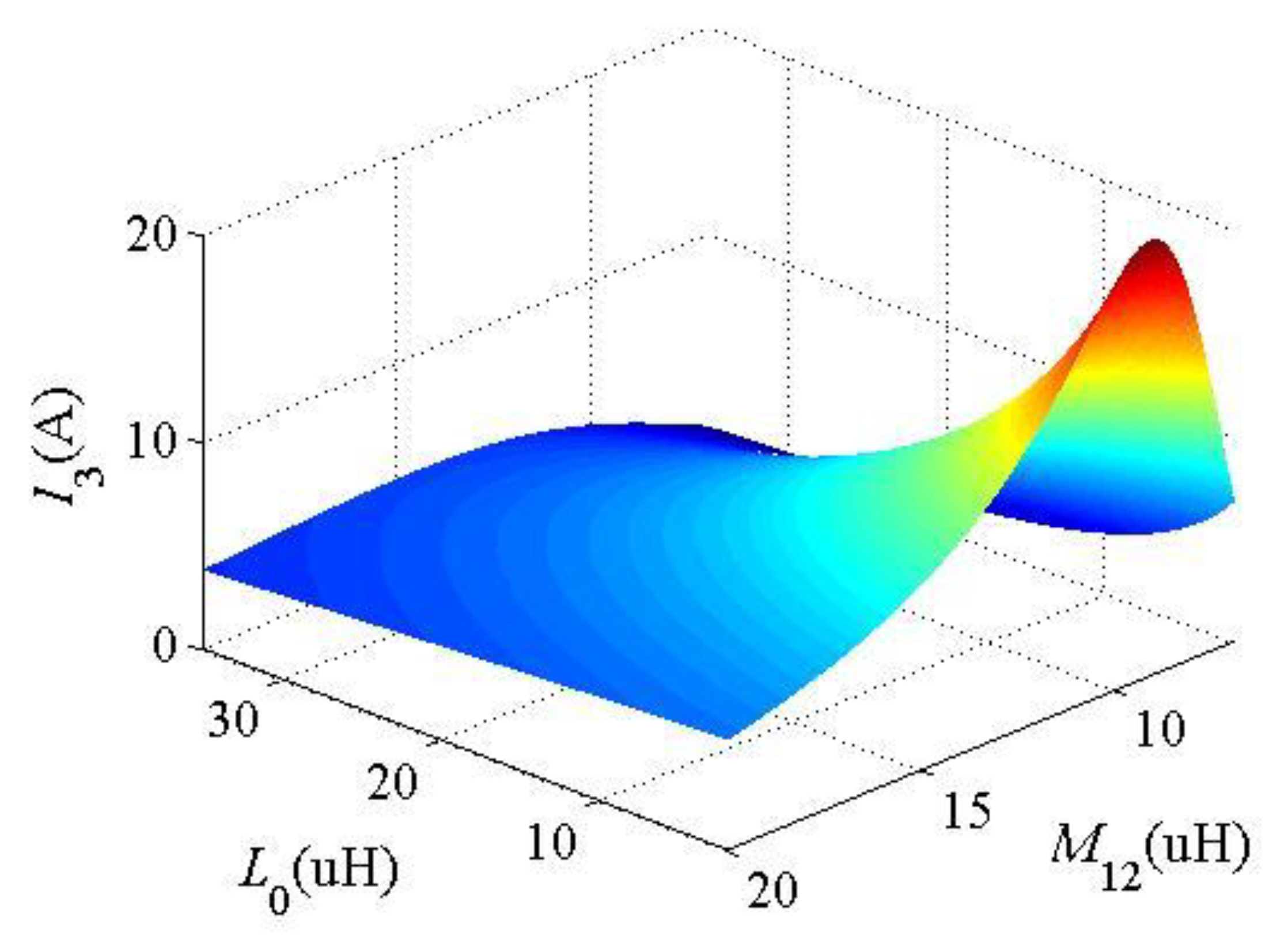
the parameters of mutual inductance M12 and the compensation inductance L0 and L5 are optimized in Figure 7. In the PSO process, the particle population size N = 500, iteration number k = 100, learning factor c1 and c2 = 0.5, and inertia weight w = 1. The final parameters of L0 and L5 are 18.79 uH and 13.46 uH. From (15), the product of L0 and L5 jointly affects the output current. In order to ensure the symmetry of the circuit topology, this paper chooses to keep them consistent. Therefore, parameters of L0 and L5 are both designed as 16 uH. The current output varies with the inductance L0 and mutual inductance M12, as shown in Figure 8. When the mutual inductance varies, the output current shows a convex function, which is beneficial to realize constant current output. Thus, the other compensation parameters C0, C1, C2, C3, C4, and C5 in the proposed hybrid topology can be calculated from (1) and (3).
4. Experiment Verification
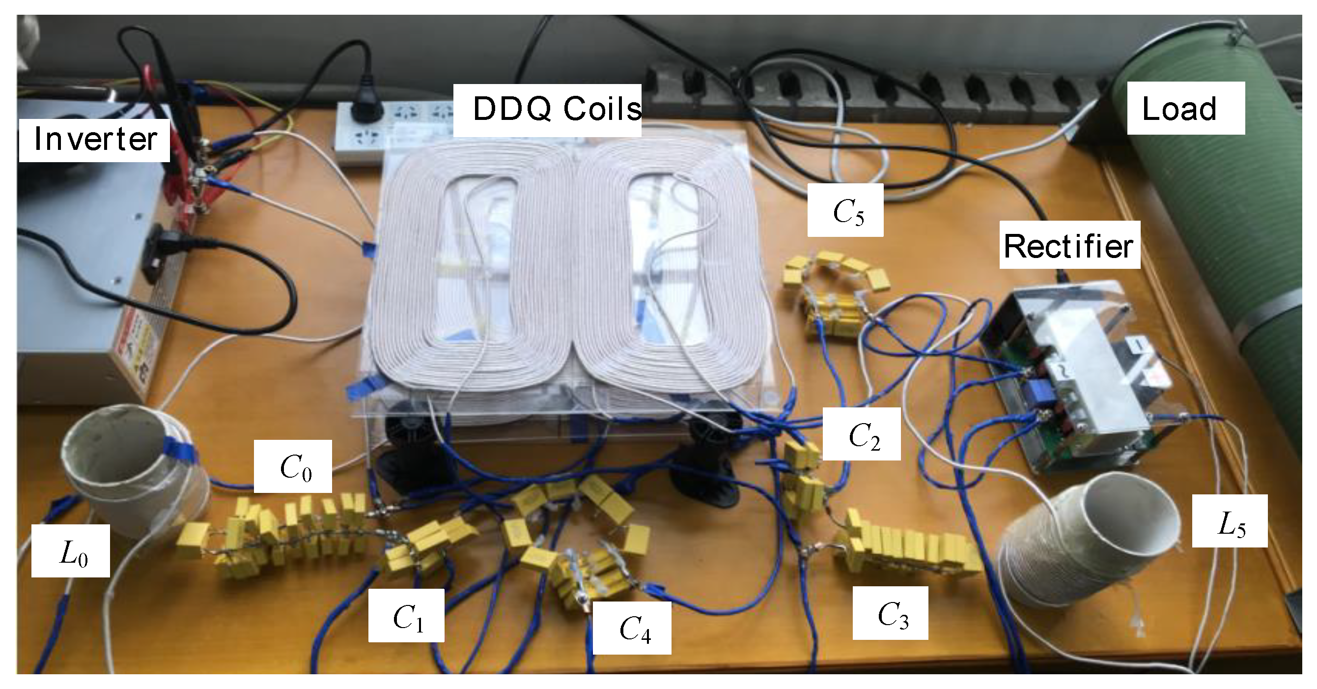
With the designed experimental parameters in Table 1, a 200 W hybrid topology wireless charging platform was built, as shown in Figure 9. The DC input voltage was 70 V, and the coefficient a and b of M12 and M34 was 0.52 and 2.17 uH, respectively. The hybrid IPT system operated with a fixed frequency at 85 kHz to validate the performance of the proposed method under misalignment conditions.
Figure 10 depicts the change in the output current when the load varies from 5 Ω to 10 Ω, and the lateral misalignment varies from 0 mm to 140 mm. The output current is between 4.25 A and 4.75 A, which illustrates that the fluctuation is less than 5%. In addition, the output current climbs initially and then drops when the X-axis misalignment occurs, which is consistent with the previous parameter optimization curve. Additionally, the output current increases to the peak at the 80 mm X-axis misalignment. The experimental results clearly validate the feasibility of the PSO parameter optimization, which can realize a wide range of anti-migration outputs.
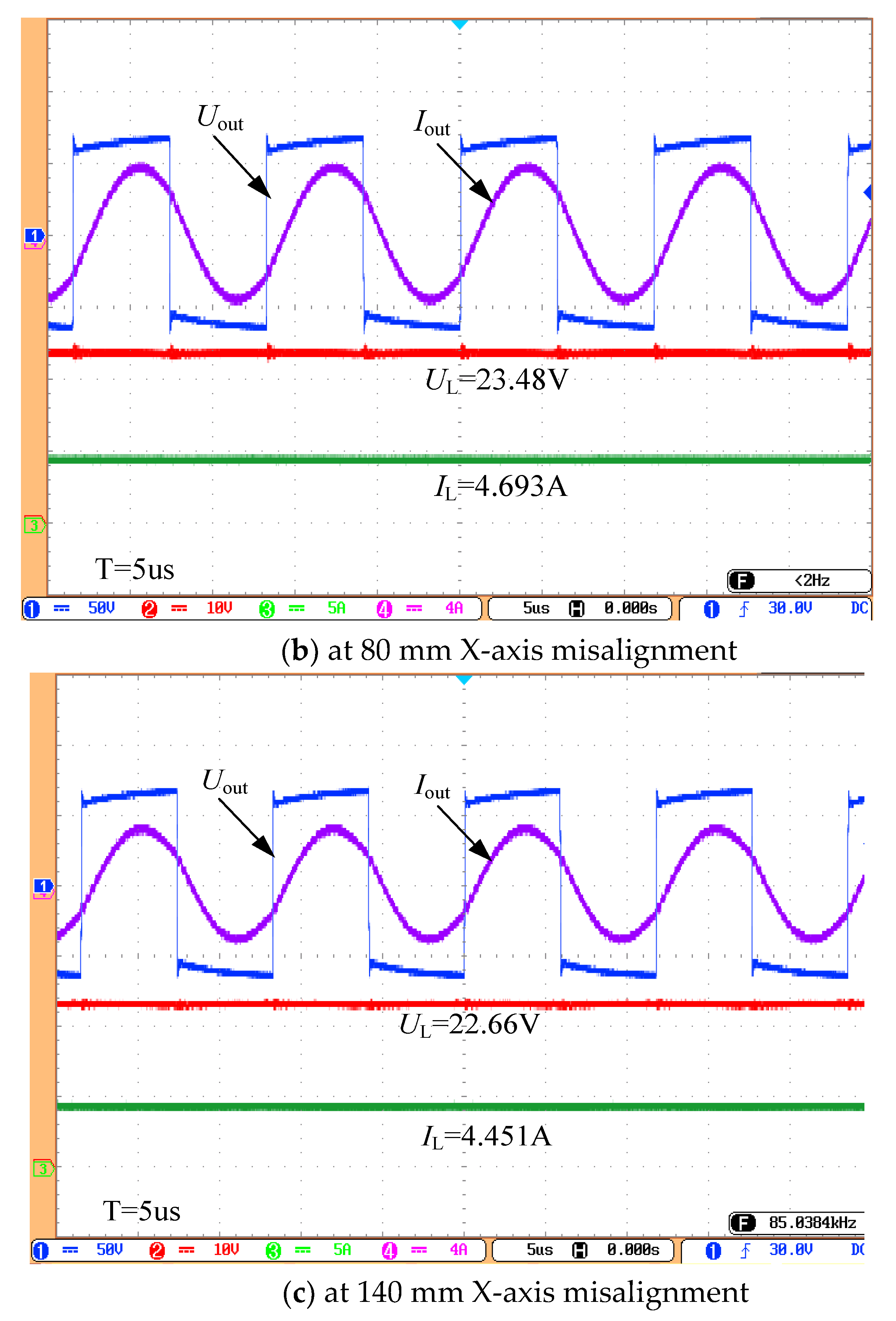
Figure 11 illustrates the experimental waveforms of the load at RL = 5 Ω with different misalignments. The maximum and minimum output current of the load at RL = 5 Ω and 10 Ω is 4.693 A and 4.451 A, respectively. Additionally, the total current fluctuation is less than 5%. Moreover, during the pads misalignment process, the output voltage is ahead of the output current, which means that the IPT system can achieve ZVS.
The experimental waveforms of the load at RL 10 Ω with different misalignments are shown in Figure 12. It is clear that the output current is 4.485 A, 4.665 A, and 4.383 A, respectively. In addition, the output current at RL = 10 Ω is slightly lower than the output current at RL = 5 Ω because the parasitic impedance results in a lower output under heavy load than under light load, which is consistent with theoretical analysis.
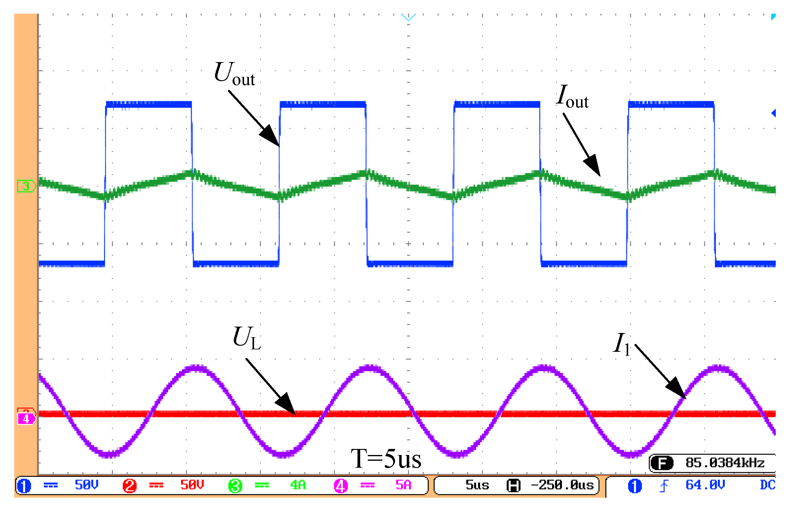
Figure 13 shows the experimental waveforms without a secondary side. It is clear that the output current of the inverter is less than 1 A, which illustrates that the output current is small enough and the system can operate safely without additional control schemes, which is consistent with theoretical analysis. In addition, the output current I1 of the L1 coil works in a resonant state, and the output current presents pure sine.
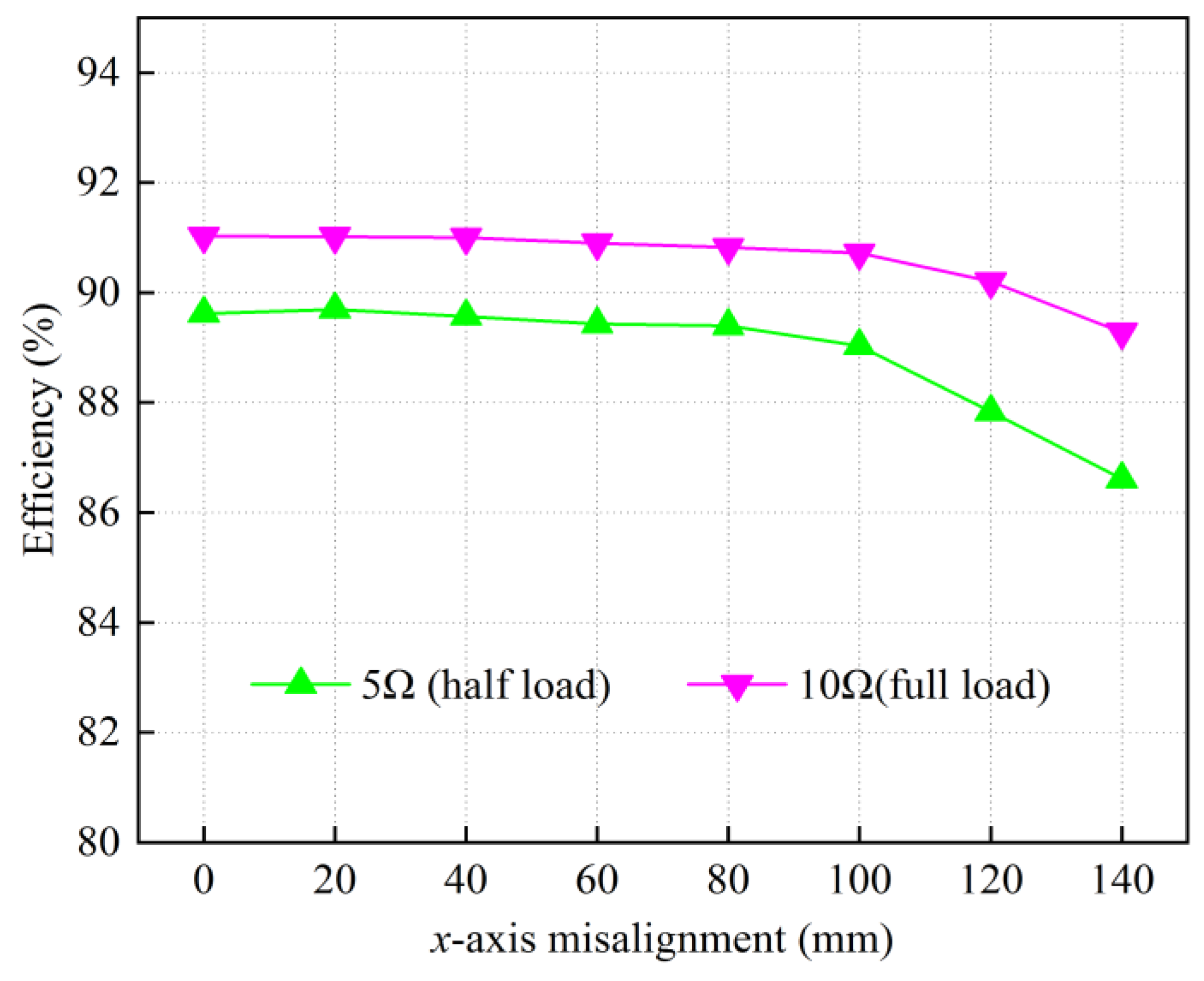
The output power and efficiency of the system under different load and misalignment conditions is shown in Figure 14 and Figure 15, respectively. It is evident that the output power can achieve relatively stable conditions when the misalignment varies from 0 mm to 140 mm, which can reach 50% of the DDQ coil. Additionally, the maximum output power is 220 W at RL = 10 Ω when the X-axis misalignment is 80 mm. As shown in Figure 14, the efficiency decreases as the X-axis misalignment increases because the power loss on the parasitic impedance of the IPT hybrid system increases relatively. Moreover, the maximum efficiency is up to 91%.
Several comparisons have been made in Table 2. Compared with [12,15], this work can achieve misalignment tolerance without complex controls and additional wireless communication. In addition, this work has less resonant components compared with [30], which can reduce the volume and cost. Compared with [28,30], this work can safely operate when the secondary side is out of working region, which can improve the stability and safety of the system. Moreover, this work proposes a PSO parameter optimization method, which is beneficial to reduce the complexity of system parameter optimization design [28,29,30].
5. Conclusions
This paper proposed a hybrid topology based on parameter optimization method to achieve load-independent current output against wide misalignment. The mathematical model with parasitic impedance was established, and the influence of parasitic impedance on system output was summarized. In addition, DDQ coils were employed against system key parameter changes, and the particle swarm optimization method was presented to achieve a nearly constant current output without using complex control schemes. In the experiment, the variation in the system output current was less than 5% when the misalignment of the coupling pad changed from 0 mm to 140 mm. The results clearly verified that the hybrid IPT topology based on the PSO method had good misalignment performance against misalignment and load variations.
Author Contributions
Conceptualization, Z.G., J.L. and X.T.; methodology, Z.G., J.L. and X.T.; software, Z.G.; validation, Z.G., J.L. and X.T.; formal analysis, Z.G.; investigation, Z.G. and J.L.; resources, J.L. and X.T.; data curation, J.L. and X.T.; writing—original draft preparation, Z.G.; writing—review and editing, Z.G., J.L. and X.T.; visualization, Z.G., J.L. and X.T.; supervision, J.L. and X.T.; project administration, Z.G. and J.L.; funding acquisition, Z.G. and J.L. All authors have read and agreed to the published version of the manuscript.
Funding
This research was funded by the Key Research Project of Shaanxi Province of China under Grant 2022GY-310.
Acknowledgments
This work was supported by the Key Research Project of Shaanxi Province of China under Grant 2021KWZ-20, 2021JY-324 and 2022JQ-424, and the Xi 'an Science and Technology Planning Project under Grant 21XJZZ0029.
Conflicts of Interest
The authors declare no conflict of interest.
References
- Wang, Y.; Zhang, H.; Lu, F. 3.5-kW 94.2% DC–DC Efficiency Capacitive Power Transfer with Zero Reactive Power Circulating. IEEE Trans. Power Electron. 2023, 38, 1479–1484. [Google Scholar] [CrossRef]
- Gong, Z.; Li, J.; Tong, X. Misalignment-Tolerant Series Hybrid with Active Adjustable Constant Current and Constant Voltage Output Wireless Charging System. Energies 2021, 14, 7594–7611. [Google Scholar] [CrossRef]
- Wu, J.; Dai, X.; Gao, R.; Jiang, J. A Coupling Mechanism with Multi-degree Freedom for Bidirectional Multistage WPT System. IEEE Trans. Power Electron. 2021, 36, 1376–1387. [Google Scholar] [CrossRef]
- Gu, P.; Wang, Y.G.; Mai, J.; Yao, Y.; Gao, S.; Huang, S.; Xu, D.G. A Three-Stage-Five-Coil IPT System Based on Cylindrical Solenoid Coupler Applied to State Detection Equipment of HV Device. IEEE Trans. Power Electron. 2022, 37, 2382–2393. [Google Scholar] [CrossRef]
- Mi, C.C.; Buja, G.; Choi, S.Y.; Rim, C.T. Modern Advances in Wireless Power Transfer Systems for Roadway Powered Electric Vehicles. IEEE Trans. Ind. Electron. 2016, 63, 6533–6545. [Google Scholar] [CrossRef]
- Dai, X.; Li, X.; Li, Y.; Sun, Y. Impedance-Matching Range Extension Method for Maximum Power Transfer Tracking in IPT System. IEEE Trans. Power Electron. 2018, 33, 4419–4428. [Google Scholar] [CrossRef]
- Yang, B.; Lu, Y.; Peng, Y.; He, S.; Chen, Y.; He, Z.; Mai, R.; Wang, Z. Analysis and Design of A T/S Compensated IPT System for AGV Maintaining Stable Output Current Versus Air Gap and Load Variations. IEEE Trans. Power Electron. 2022, 37, 6217–6228. [Google Scholar] [CrossRef]
- Chen, Y.; He, S.; Yang, B.; Chen, S.; He, Z.; Mai, R. Reconfigurable Rectifier-Based Detuned Series-Series Compensated IPT System for Anti-Misalignment and Efficiency Improvement. IEEE Trans. Power Electron. 2023, 38, 2720–2729. [Google Scholar] [CrossRef]
- Zhou, L.; Mai, R.; Liu, S.; Yu, J.; Li, Y.; Fu, L. Minimizing Input Current of the Rectifier Of LCC-LCC Compensated IPT Systems by Switch-Controlled Capacitor for Improving Efficiency. IEEE Trans. Ind. Appl. 2022, 58, 1010–1021. [Google Scholar] [CrossRef]
- Li, J.; Zhang, X.; Tong, X. Research and Design of Misalignment-Tolerant LCC–LCC Compensated IPT System With Constant-Current and Constant-Voltage Output. IEEE Trans. Power Electron. 2023, 38, 1301–1313. [Google Scholar] [CrossRef]
- Yang, B.; Chen, Y.; Ruan, W.; Liu, H.; Ren, Y.; Mai, R. Current Stress Optimization for Double-Sided CLLLC Topology-Based IPT System with Constant Output Current Tolerating Pad Misalignments. IEEE Trans. Ind. Appl. 2022, 58, 1032–1043. [Google Scholar] [CrossRef]
- Zaheer, A.; Neath, M.; Beh, H.Z.Z.; Covic, G.A. A Dynamic EV Charging System for Slow Moving Traffic Applications. IEEE Trans. Transp. Electrification 2017, 3, 354–369. [Google Scholar] [CrossRef]
- Dai, X.; Li, X.; Li, Y.; Hu, A.P. Maximum Efficiency Tracking for Wireless Power Transfer Systems with Dynamic Coupling Coefficient Estimation. IEEE Trans. Power Electron. 2018, 33, 5005–5015. [Google Scholar] [CrossRef]
- Miller, J.M.; Onar, O.C.; Chinthavali, M. Primary-Side Power Flow Control of Wireless Power Transfer for Electric Vehicle Charging. IEEE J. Emerg. Sel. Top. Power Electron. 2015, 3, 147–162. [Google Scholar] [CrossRef]
- Zhang, X.; Liu, F.; Mei, T. Multifrequency Phase-Shifted Control for Multiphase Multiload MCR WPT System to Achieve Targeted Power Distribution and High Misalignment Tolerance. IEEE Trans. Power Electron. 2021, 36, 991–1003. [Google Scholar] [CrossRef]
- Wang, C.-S.; Covic, G.; Stielau, O. Power Transfer Capability and Bifurcation Phenomena of Loosely Coupled Inductive Power Transfer Systems. IEEE Trans. Ind. Electron. 2004, 51, 148–157. [Google Scholar] [CrossRef]
- Zhao, J.; Cai, T.; Duan, S.; Feng, H.; Chen, C.; Zhang, X. A General Design Method of Primary Compensation Network for Dynamic WPT System Maintaining Stable Transmission Power. IEEE Trans. Power Electron. 2016, 31, 8343–8358. [Google Scholar] [CrossRef]
- Lu, F.; Zhang, H.; Hofmann, H.; Su, W.; Mi, C.C. A Dual-Coupled LCC-Compensated IPT System with A Compact Magnetic Coupler. IEEE Trans. Power Electron. 2018, 33, 6391–6402. [Google Scholar] [CrossRef]
- Chen, Y.; Yang, B.; Li, Q.; Feng, H.; Zhou, X.; He, Z.; Mai, R. Reconfigurable Topology for IPT System Maintaining Stable Transmission Power Over Large Coupling Variation. IEEE Trans. Power Electron. 2020, 35, 4915–4924. [Google Scholar] [CrossRef]
- Feng, H.; Cai, T.; Duan, S.; Zhang, X.; Hu, H.; Niu, J. A Dual-Side-Detuned Series-Series Compensated Resonant Converter for Wide Charging Region in A Wireless Power Transfer System. IEEE Trans. Ind. Electron. 2018, 65, 2177–2188. [Google Scholar] [CrossRef]
- Feng, H.; Cai, T.; Duan, S.; Zhao, J.; Zhang, X.; Chen, C. An LCC-Compensated Resonant Converter Optimized for Robust Reaction to Large Coupling Variation in Dynamic Wireless Power Transfer. IEEE Trans. Ind. Electron. 2016, 63, 6591–6601. [Google Scholar] [CrossRef]
- Zhao, L.; Thrimawithana, D.J.; Madawala, U.K.; Hu, A.P. A Push-Pull Parallel Resonant Converter-Based Bidirectional IPT System. IEEE Trans. Power Electron. 2020, 35, 2659–2667. [Google Scholar] [CrossRef]
- Zhang, Z.; Zhang, B. Angular-Misalignment Insensitive Omnidirectional Wireless Power Transfer. IEEE Trans. Ind. Electron. 2020, 67, 2755–2764. [Google Scholar] [CrossRef]
- Chen, Y.; Yang, B.; Zhou, X.; Li, Q.; He, Z.; Mai, R.; Lai, J.-S. A Hybrid Inductive Power Transfer System with Misalignment Tolerance Using Quadruple-D Quadrature Pads. IEEE Trans. Power Electron. 2020, 35, 6039–6049. [Google Scholar] [CrossRef]
- Yao, Y.; Wang, Y.; Liu, X.; Pei, Y.; Xu, D.G. A Novel Unsymmetrical Coupling Structure Based on Concentrated Magnetic Flux for High-Misalignment IPT Applications. IEEE Trans. Power Electron. 2019, 34, 3110–3123. [Google Scholar] [CrossRef]
- Mai, J.; Wang, Y.; Yao, Y.; Sun, M.; Xu, D. High-Misalignment-Tolerant IPT Systems with Solenoid and Double-D Pads. IEEE Trans. Ind. Electron. 2022, 69, 3527–3535. [Google Scholar] [CrossRef]
- Zhao, L.; Thrimawithana, D.J.; Madawala, U.K.; Hu, A.P.; Mi, C.C. A Misalignment-Tolerant Series-Hybrid Wireless EV Charging System with Integrated Magnetics. IEEE Trans. Power Electron. 2019, 34, 1276–1285. [Google Scholar] [CrossRef]
- Zhao, L.; Thrimawithana, D.J.; Madawala, U.K. Hybrid Bidirectional Wireless EV Charging System Tolerant to Pad Misalignment. IEEE Trans. Ind. Electron. 2017, 64, 7079–7086. [Google Scholar] [CrossRef]
- Qu, X.; Yao, Y.; Wang, D.; Wong, S.-C.; Tse, C.K. A Family of Hybrid IPT Topologies with Near Load-Independent Output and High Tolerance to Pad Misalignment. IEEE Trans. Power Electron. 2020, 35, 6867–6877. [Google Scholar] [CrossRef]
- Chen, Y.; Yang, B.; Kou, Z.; He, Z.; Cao, G.; Mai, R. Hybrid and Reconfigurable IPT Systems with High-Misalignment Tolerance for Constant-Current and Constant-Voltage Battery Charging. IEEE Trans. Power Electron. 2018, 33, 8259–8269. [Google Scholar] [CrossRef]
Figure 1.
The hybrid topology containing parasitic impedance.

Figure 2.
The output current I3 with parasitic resistances a and b.

Figure 3.
The output efficiency with parasitic resistances a and b.

Figure 4.
The DDQ magnetic coupler.

Figure 5.
The measured self and mutual inductances of the DDQ pads.


Figure 7.
Profile of fitness with respect to particle generation.

Figure 8.
Current output of the hybrid IPT system with the PSO parameters.

Figure 9.
Experimental platform.

Figure 10.
Measured output current with different load and misalignment.

Figure 11.
Experimental waveforms at RL = 5Ω.


Figure 12.
Experimental waveforms at RL = 10 Ω.

Figure 13.
Experimental waveforms without the secondary side.

Figure 14.
The output power under different load and misalignment conditions.

Figure 15.
The efficiency under different load and misalignment conditions.


Table 1.
Experimental parameters of the system.
| Parameter | Value | Parameter | Value |
|---|---|---|---|
| f | 85 kHz | C5 | 26.5 nF |
| L0 | 16.1 uH | E | 70 V |
| L1 | 150.1 uH | a | 0.52 |
| L2 | 149.8 uH | b | 2.17 uH |
| L3 | 156.1 uH | RL | 5–10 Ω |
| L4 | 156.0 uH | R0 | 0.06 Ω |
| L5 | 16.1 uH | R1 | 0.42 Ω |
| C0 | 220.2 nF | R2 | 0.42 Ω |
| C1 | 26.6 nF | R3 | 0.41 Ω |
| C2 | 220.1 nF | R4 | 0.41 Ω |
| C3 | 22.5 nF | R5 | 0.07 Ω |
| C4 | 22.5 nF |
Table 2.
Comparisons with existing topologies.
| Proposed in | Ref. [12] | Ref. [15] | Ref. [28] | Ref. [29] | Ref. [30] | This Work |
|---|---|---|---|---|---|---|
| Control strategy | Additional DC–DC | pulse frequency modulation | No | No | No | No |
| Number of Component | 5 | 4 | 8 | 8 | 12 | 8 |
| Coupling coils | BPs | Multi-phase coils | DDs | DDQs | DDQs | DDQs |
| output characteristic | CV | CV | CC | CV | CC-CV | CV |
| Parameter optimization | / | / | / | Complex | Complex | Easy |
| Wireless communication | Yes | Yes | No | No | No | No |
| Operate without secondary side | / | / | No | Yes | No | Yes |
Disclaimer/Publisher’s Note: The statements, opinions and data contained in all publications are solely those of the individual author(s) and contributor(s) and not of MDPI and/or the editor(s). MDPI and/or the editor(s) disclaim responsibility for any injury to people or property resulting from any ideas, methods, instructions or products referred to in the content. |
© 2023 by the authors. Licensee MDPI, Basel, Switzerland. This article is an open access article distributed under the terms and conditions of the Creative Commons Attribution (CC BY) license (https://creativecommons.org/licenses/by/4.0/).
Share and Cite
MDPI and ACS Style
Gong, Z.; Li, J.; Tong, X. A Misalignment-Insensitive Hybrid IPT System with Constant Current Output Based on Parameter Optimization. Electronics 2023, 12, 1138. https://doi.org/10.3390/electronics12051138
AMA Style
Gong Z, Li J, Tong X. A Misalignment-Insensitive Hybrid IPT System with Constant Current Output Based on Parameter Optimization. Electronics. 2023; 12(5):1138. https://doi.org/10.3390/electronics12051138
Chicago/Turabian StyleGong, Zhaowei, Jingang Li, and Xiangqian Tong. 2023. "A Misalignment-Insensitive Hybrid IPT System with Constant Current Output Based on Parameter Optimization" Electronics 12, no. 5: 1138. https://doi.org/10.3390/electronics12051138
Note that from the first issue of 2016, this journal uses article numbers instead of page numbers. See further details here.