Experimental and Numerical Study of Engineered Cementitious Composite with Strain Recovery under Impact Loading


1
Department of Civil and Environmental Engineering, Western University, London, ON N6G 5L1, Canada
2
Department of Civil Engineering, Military Technical College, Cairo, CA 11765, Egypt
*
Author to whom correspondence should be addressed.
Appl. Sci. 2019, 9(5), 994; https://doi.org/10.3390/app9050994
Submission received: 22 October 2018
/
Revised: 15 February 2019
/
Accepted: 1 March 2019
/
Published: 10 March 2019
(This article belongs to the Section Materials Science and Engineering)
Abstract
:Featured Application
Construction of protective structures with superior impact and blast resistance.
Abstract
An engineered cementitious composite, endowed with strain recovery and incorporating hybrid shape memory alloy (SMA) and polyvinyl alcohol (PVA) short fibers, was subjected to drop weight impact loading. Numerical simulation of the composite’s impact behavior was performed, and the model predictions agreed well with the experimental findings. Numerical and experimental investigations demonstrated that incorporating SMA fibers in the composite yielded superior impact resistance compared to that of control mono-PVA specimens. Heat treatment stimulated the SMA fibers to apply local prestress on the composite’s matrix owing to the shape memory effect, thus enhancing energy absorption capacity, despite the damage incurred by PVA fibers during the heating process. The superior impact performance of the hybrid composite makes it a strong contender for the construction of protective structures, with a potential to enhance the safety of critical infrastructure assets against impact and blast loading.
1. Introduction
Missiles, bombs, aircraft and truck crashes, accidental explosions, and rock falls have been major threats to civilian structures and military facilities [1]. There have also been rapid advances in the technology of explosives and ammunition over the last few decades, about not only its destructive capacity but also its sophisticated ability to penetrate the aimed target. Coupled with the growing number of intended attacks on civilian infrastructure, a superior level of protection against explosive and impact loading will be required in the future.
Reinforced concrete has been the construction material of choice for critical civilian infrastructure and defensive structures. Due to its low tensile strength, concrete exhibits brittle failure under dynamic loading, which can compromise structural integrity and safety within and near protective facilities. When a structural concrete element is subjected to dynamic loadings, such as impacts or explosions, it experiences unique states of stresses. For instance, near the impacted location, severe hydrostatic compression can propagate, and the state of stress irreversibly compresses the concrete. Simultaneously, away from the impacted area, confinement stresses are decreased, and the concrete undergoes compression with a moderate state of stress. Moreover, the reflected rear face compressive wave of the target produces tensile waves, which interacts with compressive waves possibly leading to spalling of the concrete [2].
Incorporating randomly discrete short fibers in concrete yields significant improvements in engineering properties, such as tensile and flexural capacities, ductility, resistance to fatigue, and impact loading [3]. In the early 2000s, a new kind of fiber-reinforced cementitious composite, commonly known as Engineered Cementitious Composite (ECC), had emerged. ECC exhibits superior tensile characteristics compared to that of conventional fiber-reinforced concrete (FRC) with strain capacity of up to 8% [4]. Owing to its superior mechanical performance, unique micro-cracking capability, energy absorption capacity, and impact resistance, ECC has become a strong contender for the construction of protective structures [5]. Cement, supplementary cementitious materials, micro-sand (typically less than 200 microns), water, and short fibers are the main constituents of ECC. Polyvinyl alcohol (PVA), polypropylene (PP), polyethylene (PE), rubber, and steel (SE) fibers have been utilized in the production of ECC. Recently, the authors have pioneered the use of short shape memory alloy (SMA) fibers in ECC production [6]. SMAs are a class of metallic alloys that “remember” their original shape, with unique ability to undergo large inelastic deformation and regain its un-deformed shape when subjected to stimuli, such as radiation, thermo-mechanical or magnetic variations, and electric heating.
The unique behavior of ECC structural elements under impact loading has triggered significant research aiming at the development of design guidelines for ECC in protective structures. On the other hand, several experimental and numerical investigations have been conducted on the impact resistance of ECC elements. The most pertinent recent research work focused on the impact behavior of cement-based materials reinforced by mono-fibers [7,8,9] and/or hybrid-fibers with two different types of fibers or more [10,11,12]. Due to technical difficulties and the high cost of conducting large-scale missile impact tests, often small-scale drop weight impact testing has rather been adopted, despite the limitations associated with such a testing approach. For instance, Maalej et al. [13] investigated the impact resistance of hybrid-fiber ECC panels reinforced with 1.5% polyethylene (PE) and 0.5% steel fibers. Results showed that the ECC panels could perform as a protective material in various applications, such as improving shatter resistance with reduced scabbing and spalling associated with distributed micro-cracking. Furthermore, Yang and Li [14] conducted a series of drop weight impact tests on hybrid-fiber-reinforced ECC panels and beams incorporating PVA and PE fibers. It was observed that the ductility of ECC specimens led to enhanced impact resistance through improving the load carrying capacity and energy dissipation capability of the tested structural elements. Similarly, Soe et al. [10] concluded that a hybrid-fiber reinforced ECC incorporating a combination of 1.75% PVA and 0.58% steel fibers achieved superior performance and dissipated more energy when subjected to high-velocity projectiles than that of a control conventional concrete. Recently, Ali et al. [6] experimentally investigated the impact resistance of SMA-ECC composites under drop weight impact. Up to six hundred blows were applied per specimen to cause a fracture, which reflects the time and efforts required to conduct such tests. Therefore, numerical simulation is a highly attractive alternative considering the costs and difficulties of experimental tests.
For an accurate numerical prediction of the impact behavior of ECC structures, adequate material models, which can represent the dynamic behavior of ECC, are essential [2]. Various commercial codes have emerged modeling the dynamic behavior of concrete materials, such as ABAQUS, ANSYS, AUTODYN, and LS-DYNA. Various material models representing different types of concrete have been proposed for impact analysis [15,16,17]. However, they often require many input parameters, some of which have no clear physical meaning and cannot be estimated by traditional material tests [18]. So far, there is a dearth of numerical studies on the behavior of ECCs under dynamic loading.
For instance, Chin [19] utilized the LS-DYNA code in modeling the behavior of hybrid-fiber ECC panels under drop-weight impact loading. It was observed that the Finite Element (FE) model gave a reasonable prediction of the local and global responses of the ECC panels and closely predicted the impact load-time histories of the impactor. Likewise, Li and Zhang [2] performed a numerical simulation of ECC panels under high-velocity impact loading using the LS-DYNA code. Their results demonstrated the effectiveness of the proposed model in simulating the dynamic behavior of ECC materials. Recently, Anil et al. [20] conducted an FE study on ECC beams under impact loading using the commercial ABAQUS software package to observe the stress distribution in beams and attain an accurate and verified model capable of simulating such loading conditions. Their analytical results were in good agreement with the experimentally measured data in terms of maximum displacement and load values. In addition, they observed that the stress distribution through the beams was in reasonable agreement with the experimental crack distribution. Hence, it appears that accurate simulation and prediction of the structural response under dynamic load can be a convenient way to decrease the cost and efforts related to testing new materials and applications. The availability of powerful FE modeling codes with the flexibility to incorporate new material models developed by the user has stimulated such efforts.
In the present study, experimental testing and numerical simulation of a novel hybrid fiber-reinforced engineered cementitious composite incorporating SMA and PVA short fibers (HECC-SMAF) under impact loading were carried out, and the findings are discussed below. All test results and curves present the average values of the tested specimen in triplicate for each test.
2. Experimental Program
2.1. Materials, Sample Preparation, and Curing
Type I ordinary Portland cement conforming to ASTM C150 [21] (Standard Specification for Portland Cement), fly ash (FA) meeting the requirements of ASTM C618 [22] (Standard Specification for Coal Fly Ash and Raw or Calcined Natural Pozzolan for Use in Concrete), and micro silica-sand with a maximum particle size of 200 µm were used in this study. Polycarboxylate high-range water reducing admixture (HRWRA) in accordance with ASTM C494 [23] (Standard Specification for Chemical Admixtures for Concrete) was added as a percentage of cement weight to adjust the workability of the tested mixtures. Furthermore, two types of fibers were used: 8-mm long polyvinyl-alcohol (PVA) and 16-mm long nickel-titanium (NiTi) shape memory alloy (SMA) fibers conforming to ASTM F2063 [24] (Standard Specification for Wrought Nickel-Titanium Shape Memory Alloys for Medical Devices and Surgical Implants). Table 1 provides the mechanical characteristics of the SMA and PVA fibers, while the mixture proportions for all tested specimens are given in Table 2. The first number in the mixture label indicates the PVA fiber content, while the second number is the SMA fiber content. For instance, ECC2-1.5 refers to an engineered cementitious composite incorporating 2% PVA fiber and 1.5% SMA fiber by volume fraction.
All ECC mixtures were prepared using a 20-L concrete mixer. First, all solid ingredients, including the cement, FA, and silica sand, were dry mixed for one minute. This was followed by HRWRA and water addition over another three minutes of continuous mixing. Subsequently, PVA and SMA fibers were randomly dispersed and mixing resumed for another three minutes until fibers were uniformly distributed. Subsequently, the required test specimens from each mixture were cast. Specimens were demolded after 24-h and cured in sealed plastic bags for 7-days at T = 21 ± 2 °C) without external moisture supply, which is a common curing method for ECC. Thereafter, specimens were stored in lab conditions (T = 20 ± 2 °C and RH = 55 ± 5%) until testing.
2.2. Mechanical Properties
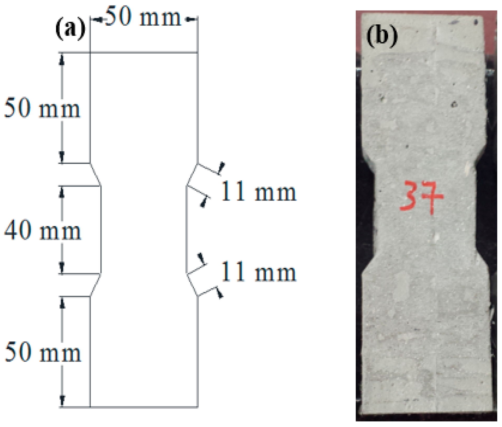
From each ECC mixture, three 50 mm × 50 mm × 50 mm cubic specimens were prepared and tested at the age of 90 days as per ASTM C39 [25] (Standard Test Method for Compressive Strength of Cylindrical Concrete Specimens) to obtain the compressive strength of the various ECC mixtures using a 2000 kN compressive testing machine. Also, three 75 mm in diameter by 150 mm in height [3 in × 6 in] cylindrical specimens were prepared and tested to evaluate the elastic modulus and Poisson’s ratio for all ECC mixtures per ASTM C469 [26] (Standard Test Method for Static Modulus of Elasticity and Poisson’s Ratio of Concrete in Compression). Three uniaxial tensile coupon specimens (Figure 1) from each ECC mixture were tested at 90 days using an Instron testing machine under displacement control and a loading rate of 0.5 mm/min. Also, a 50 mm extensometer was attached to the coupon specimens to estimate the strain capacity of each specimen. The ultimate tensile strength and strain capacity were determined directly from an automated data analysis system connected to the Instron testing machine. More details on the test procedures can be found in [6].
2.3. Drop-Weight Impact Test
Considering that large-scale missile impact tests are costly, and their results are often not available in the public domain, smaller laboratory-scale tests are more common [27]. The drop-weight impact test is one of the most widely used techniques for evaluating the impact resistance of fiber-reinforced cementitious materials [28,29,30]. In the present study, the drop weight impact test was carried out in compliance with the procedure outlined by the American Concrete Institute (ACI) Committee 544 [31], on four different ECC mixtures at the age of 90 days. Another series of similar ECC specimens were heat treated up to 150 °C to explore the shape memory effect of SMA fibers on the overall behavior of the hybrid composite under impact loading. The heat treatment was applied for 3 min using a heat gun fixed at 35 mm away from the specimen. The gun was able to heat the specimens by up to 150 °C. The heat treatment process was similar to that proposed by Kim et al. [32] and used to activate the SMA fibers, which were in the martensite phase before heating.
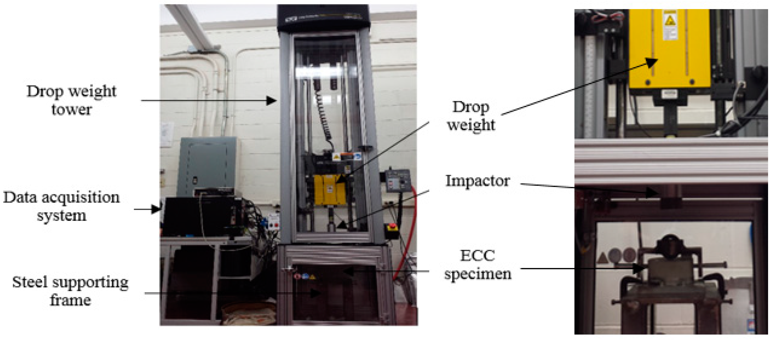
The ECC mixtures were cast in cylindrical molds having dimensions of 100 mm × 200 mm [4 in × 8 in]. Each cylindrical specimen was cut into three 100 mm × 50 mm [4 in × 2 in] discs using a diamond saw. The discs were then tested under a drop weight impactor using an Instron impact loading machine (Figure 2) with a maximum impact force of 44,000 N. Further details about the test method can be found elsewhere [33].
3. Experimental Results
3.1. Compression and Tensile Behavior
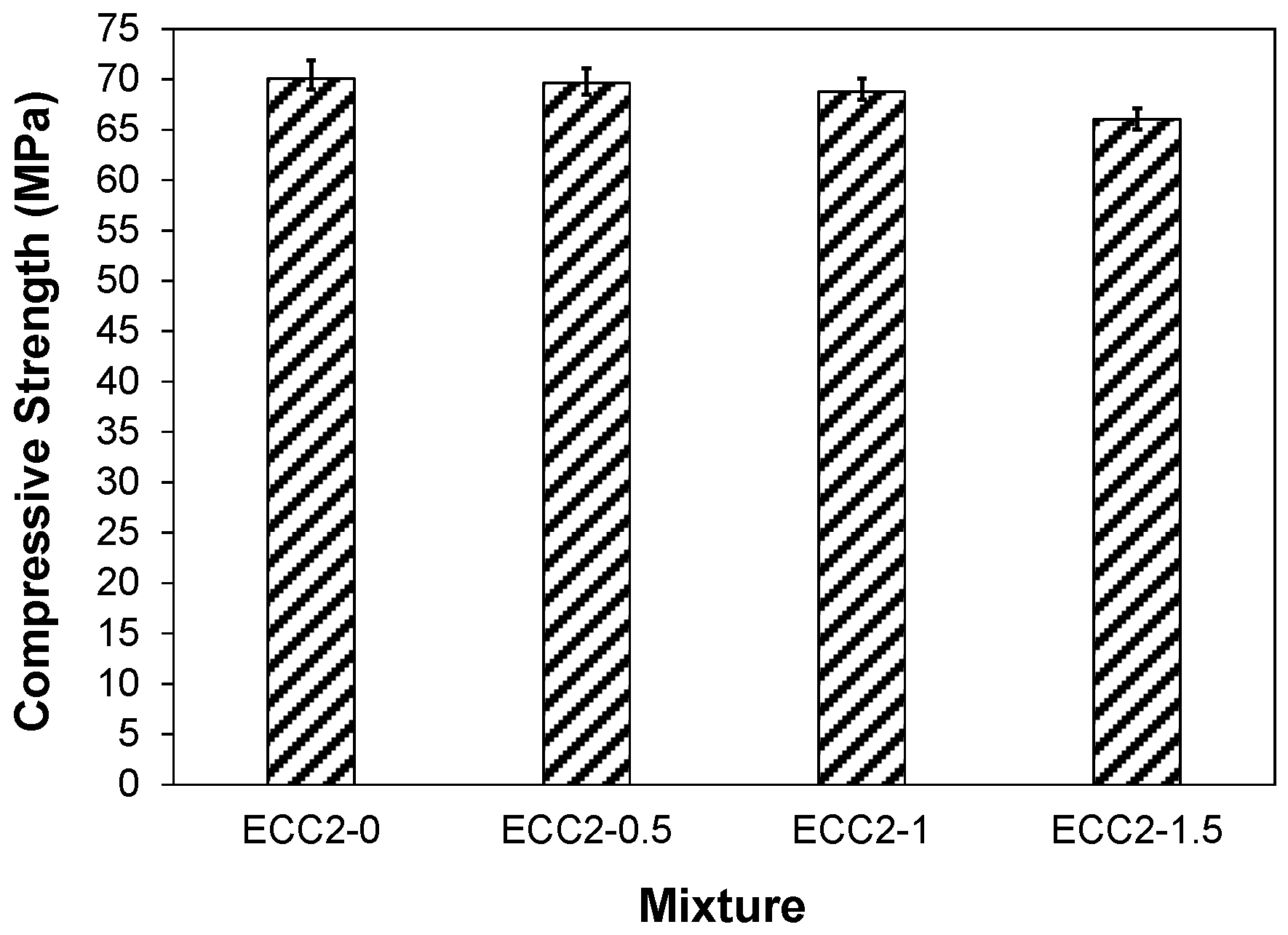
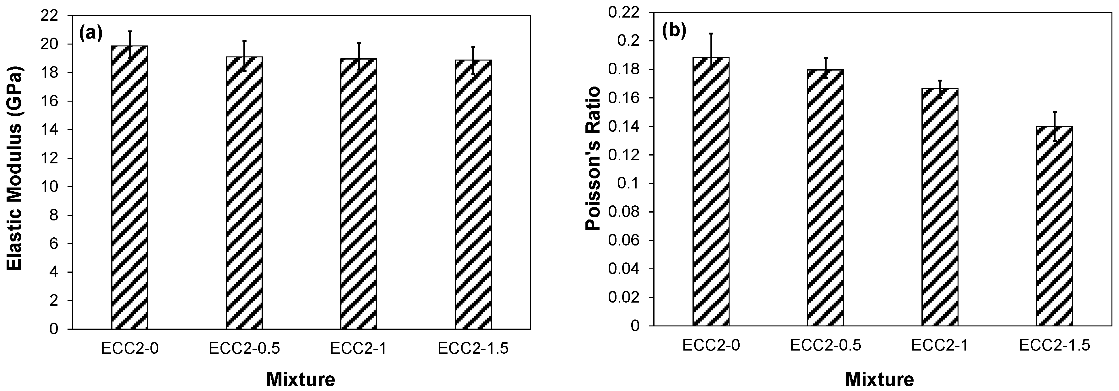
The 90-day compressive strength of the composite specimens was about 70 MPa. Figure 3 displays the variation in compressive strength test results. It can be observed that SMA fiber addition led to slight or no increase in compressive strength of the composite. For instance, the compressive strength of the ECC2-0.5, ECC2-1, and ECC2-1.5 mixtures slightly decreased by about 1.1%, 1.9%, and 5.8% compared to that of the ECC mixture produced with 2% PVA fibers alone, respectively. This is ascribed to increased porosity because of fiber clustering. Evidence of this was presented by Ali et al. [6]. Similarly, incorporating SMA fibers in ECC led to a general reduction in the elastic modulus and Poisson’s ratio of the composite compared to that of the PVA-ECC control mixture (Figure 4a,b). Also, it was observed that the elastic modulus of the different ECC mixtures was generally lower than that of comparable strength conventional concrete. This is attributed to the absence of coarse aggregates in ECC mixtures. The elastic modulus and Poisson’s ratio of ECC incorporating SMA and/or PVA fibers ranged from 18.8 to 19.9 GPa and 0.14 to 0.19, respectively, depending on the fiber type and content. The incorporation of SMA fibers in the ECC mixture led to a general reduction in the elastic modulus and Poisson’s ratio of ECC compared to that of the mono-PVA control mixture. For example, 0.5%, 1%, and 1.5% SMA fiber addition led to a reduction in elastic modulus by about 3.9%, 4.5%, and 4.7%, respectively, compared to that of the mono-PVA fiber-reinforced ECC mixture. A similar trend was observed for Poisson’s ratio. For example, specimens ECC2-0.5, ECC2-1, and ECC2-1.5 had Poisson’s ratio of 1.1%, 8.1%, and 24.3% lower than that of the control ECC2-0 specimens, respectively. The overall reduction in elastic modulus of the ECC mixtures can be ascribed to the reduced compressive strength caused by increased porosity due to fiber addition because of possible fiber clustering, while the reduction in Poisson’s ratio imparted by fibers is attributed to the fiber restriction on the lateral strain.
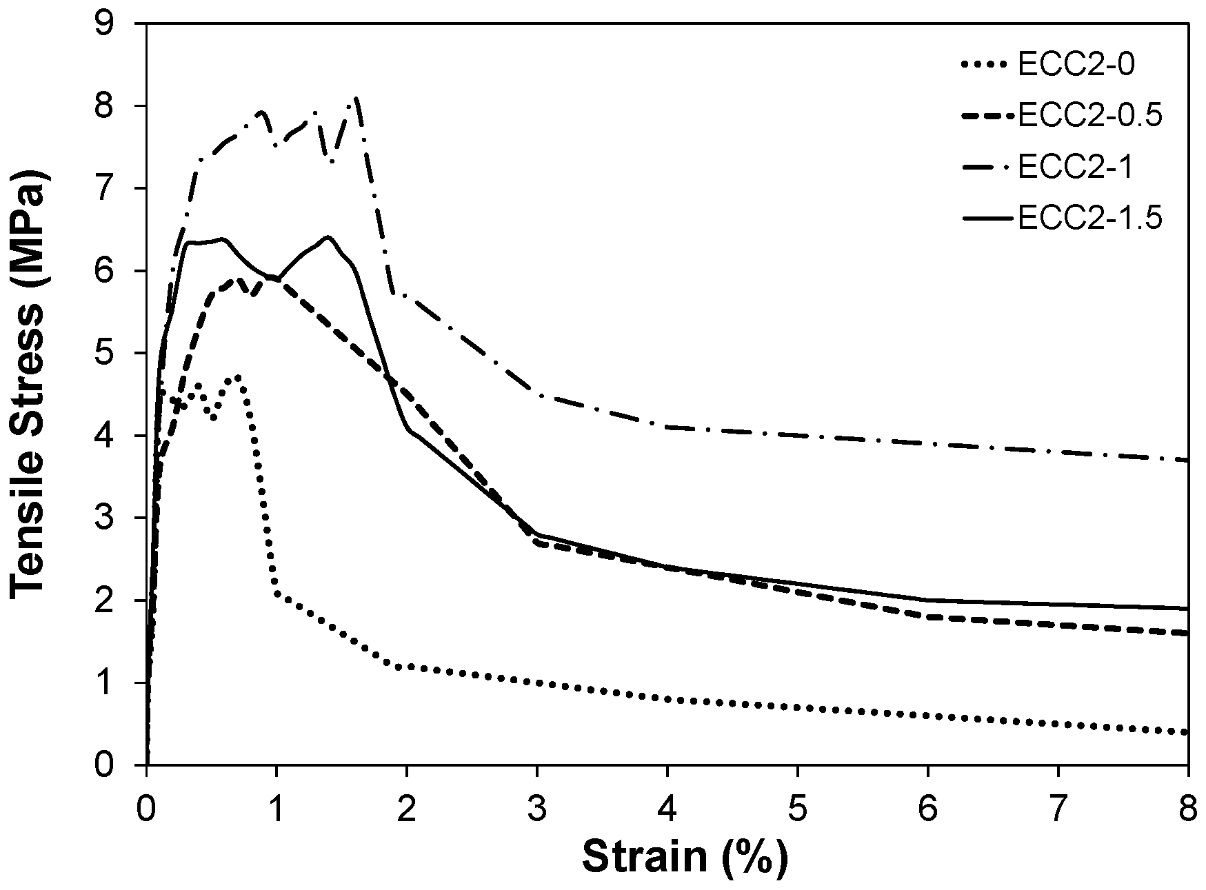
Furthermore, Figure 5 displays typical stress-strain curves from uniaxial tensile tests for the various ECC mixtures. The achieved tensile strength ranged between 6 and 8 MPa with strain capacity by up to 8%, depending on the SMA fiber content. Generally, the tensile properties of the composite were improved owing to SMA fiber addition. For instance, the ultimate tensile strength of ECC2-0.5, ECC2-1, and ECC2-1.5 specimens increased by 29.8%, 74%, and 39.8%, respectively, compared to that of mono-PVA-ECC control specimens. Also, the strain capacity corresponding to peak strength was significantly enhanced by SMA fiber addition. The enhanced tensile behavior of the hybrid ECC specimens is ascribed to enhancing the fiber-matrix interfacial bond area (i.e., chemical and frictional) via fiber addition, thus improving the overall load carrying capacity of the composite.
3.2. Impact Behavior
3.2.1. Energy Penetration
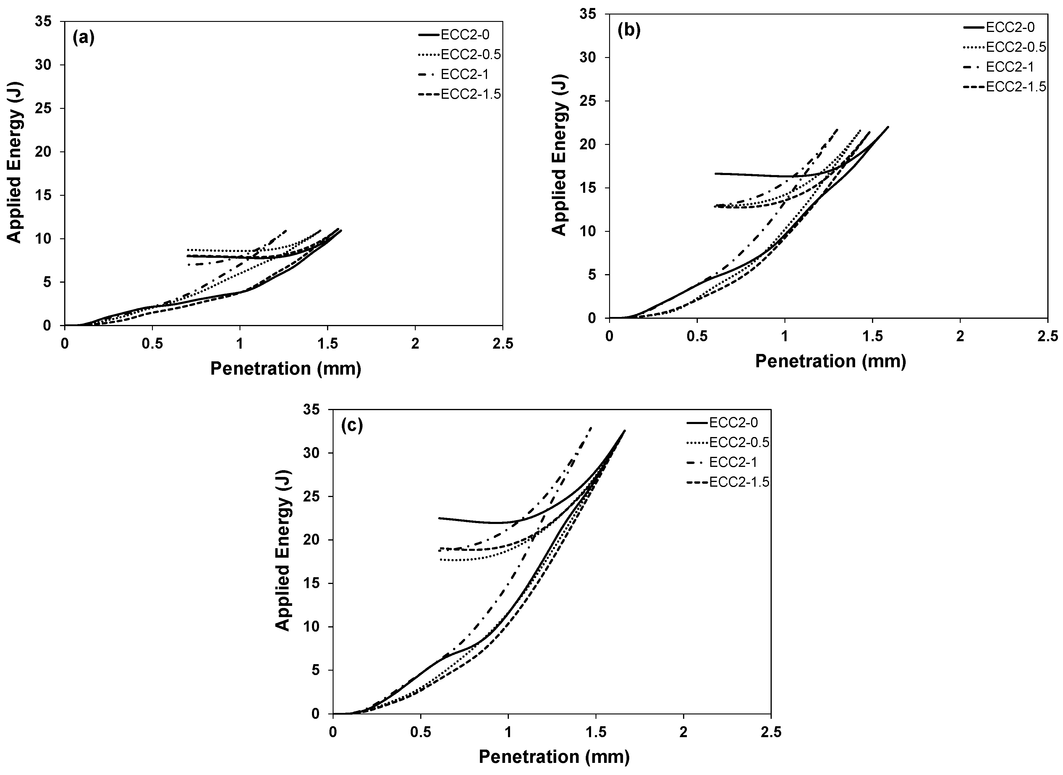
Figure 6a–c display the energy-time history curves for different composite specimens at different drop levels. Each specimen was subjected to multiple impacts at different drop levels such that the first, second, and third impacts were at 50 mm, 100 mm, and 150 mm, respectively, measured from the upper end of the spherical steel ball up to the lower end of the impactor. It was observed that all tested ECC specimens did not fail or even crack under the effect of multiple impacts up to the maximum capacity of the testing machine. Also, it was revealed that among all tested specimens, ECC2-1 showed the best performance at low impact levels, as shown in Figure 6a. ECC2-1 sustained the impact load with better energy dissipation capability and lower penetration depth compared to all other specimens. A similar trend was observed at higher levels of impact, as displayed in Figure 6b,c. Incorporating fiber dosages higher than 2% PVA and 1% SMA, led to a general reduction in the energy dissipation capability and penetration resistance at all impact levels. This is ascribed to increased porosity and tendency of fiber clustering implemented with a high dosage of fibers.
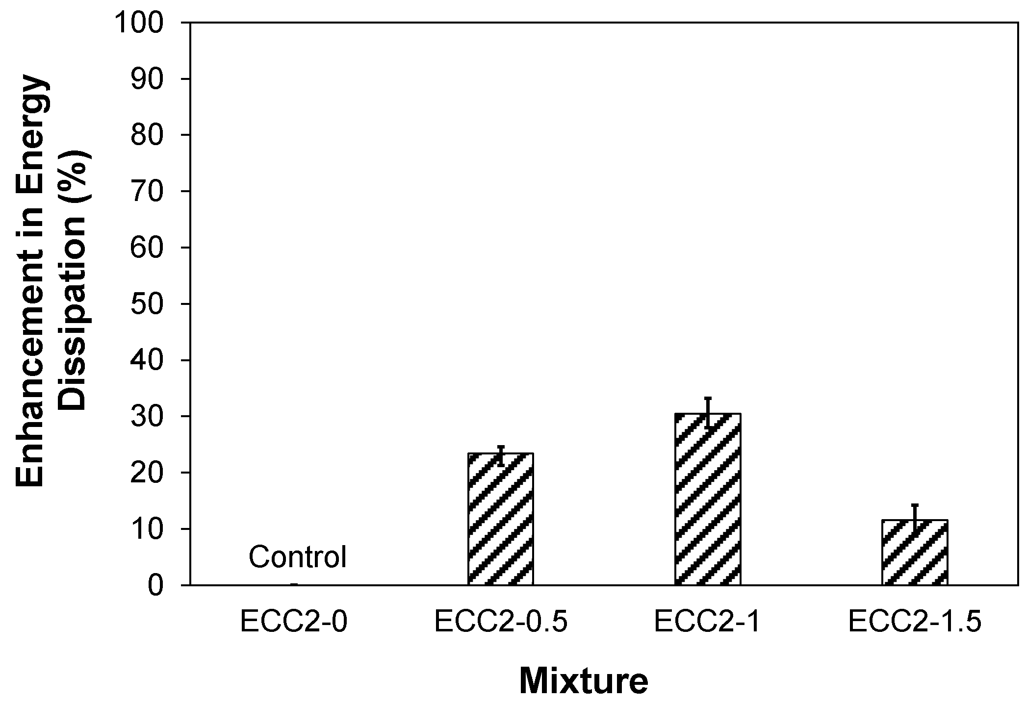
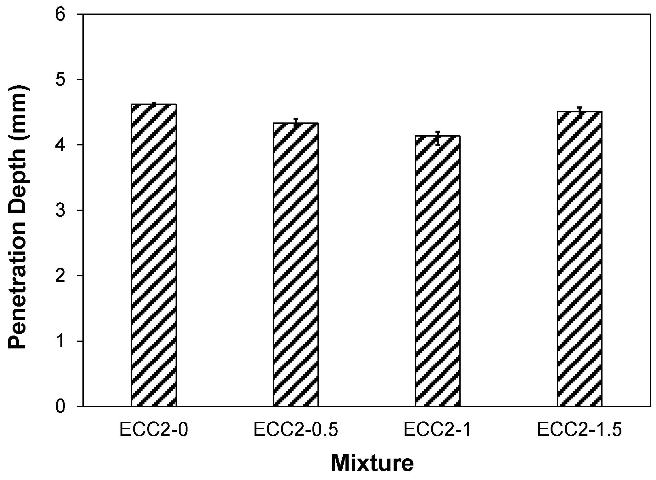
The computerized system, which was used in the data acquisition during impact, was programmed to calculate the energy dissipation capacity of the different ECC specimens through estimating the difference between the applied impact energy and that remaining in the system upon impact. The cumulative enhancement in energy dissipation capability of the ECC specimens is illustrated in Figure 7. It can be observed that the energy dissipation capability was generally improved by SMA fiber addition. For instance, the ECC2-0.5, ECC2-1, and ECC2-1.5 specimens achieved dissipated energy of 23.39%, 30.43%, and 11.53% higher than that of the control ECC specimens made with PVA fibers alone, respectively. This underscores the significant enhancement in impact resistance of the composite owing to SMA fiber addition. The accumulated impactor penetration depth in the different ECC specimens is illustrated in Figure 8. Only small penetration occurred upon impact loading. A general reduction in penetration depth was observed owing to SMA fiber addition. For example, the ECC2-0.5, ECC2-1, and ECC2-1.5 specimens had 6.3%, 10.1%, and 2.6% lower penetration depth compared to that of the control ECC2-0 specimens, respectively. This is ascribed to the resistance of the composite’s fiber-matrix interfacial frictional bond. The ECC specimen incorporating 2% PVA and 1% SMA fibers achieved the highest energy dissipation capacity and lowest penetration depth among all tested specimens. Higher fiber dosage led to impact strength degradation due to increased porosity via fiber clustering, as evidenced by the authors elsewhere [6].
3.2.2. Impact Load-Time History
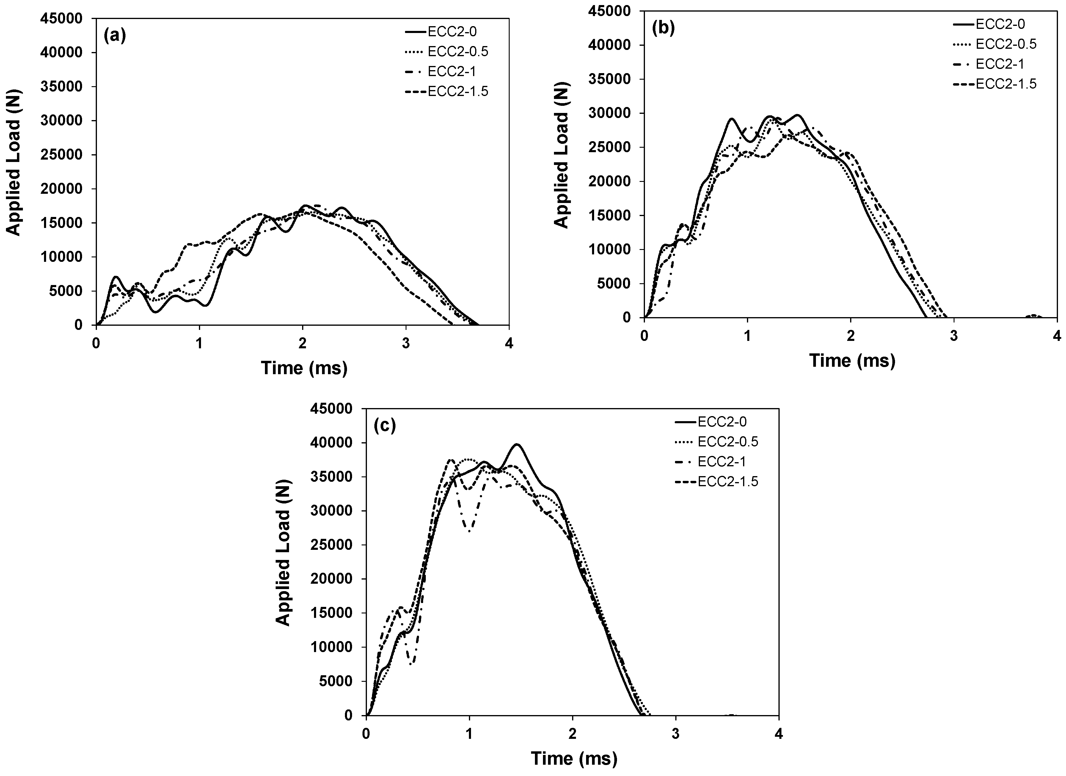
The impact load was measured during each impact as derived from the accelerometer measurements. The impact load-time history curves are displayed in Figure 9a–c. It was observed that all composite specimens did not fail or even crack under the effect of multi-impacts up to the maximum capacity of the testing machine (44,000 N). The peak impact force for hybrid mixtures, which incorporated 0.5%, 1%, and 1.5% SMA fiber, slightly increased by about 2.38%, 7.19%, and 3.03%, respectively, compared to that of the control mono PVA-ECC mixture. The ability of ECC specimens to resist impact load mainly depended on the fiber type and content. The material’s response under impact load depends on its interactive behavior under compressive and shear stresses [34]. Since all ECC mixtures had a slight difference in compressive strength, it appears that the SMA fibers-matrix bond allowed to better resist shear stresses induced by the impact load, thus leading to higher impact resistance.
3.2.3. Local Pre-Stressing Effect
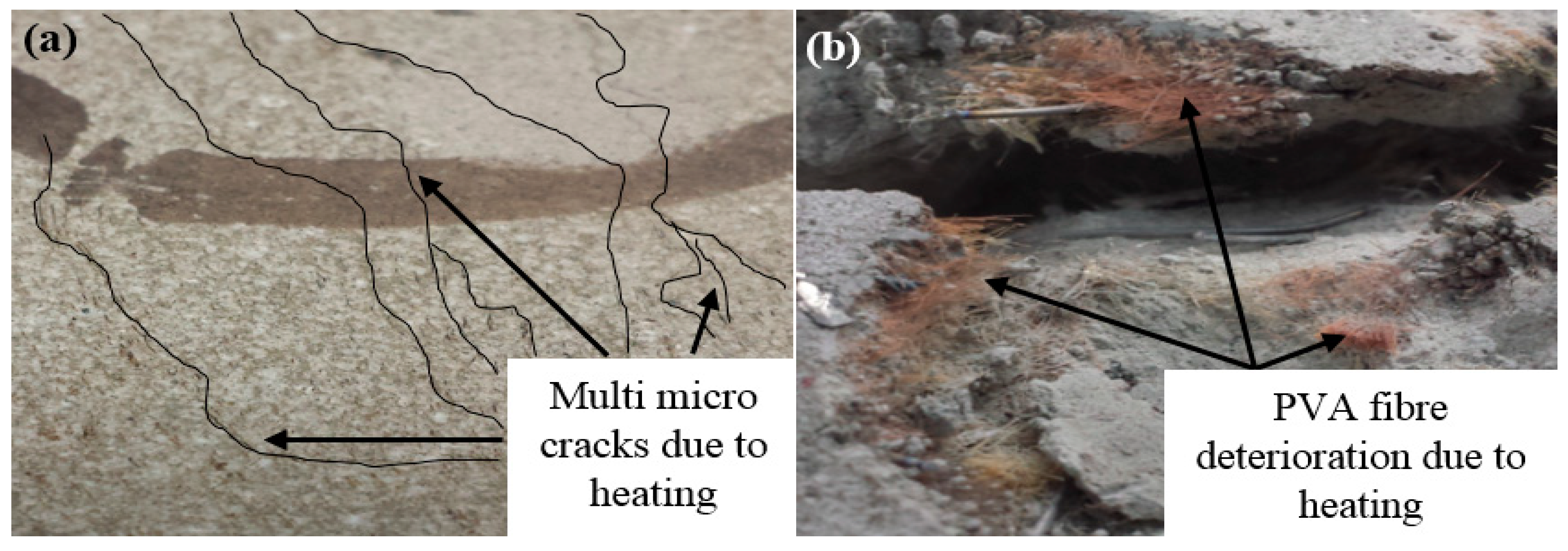
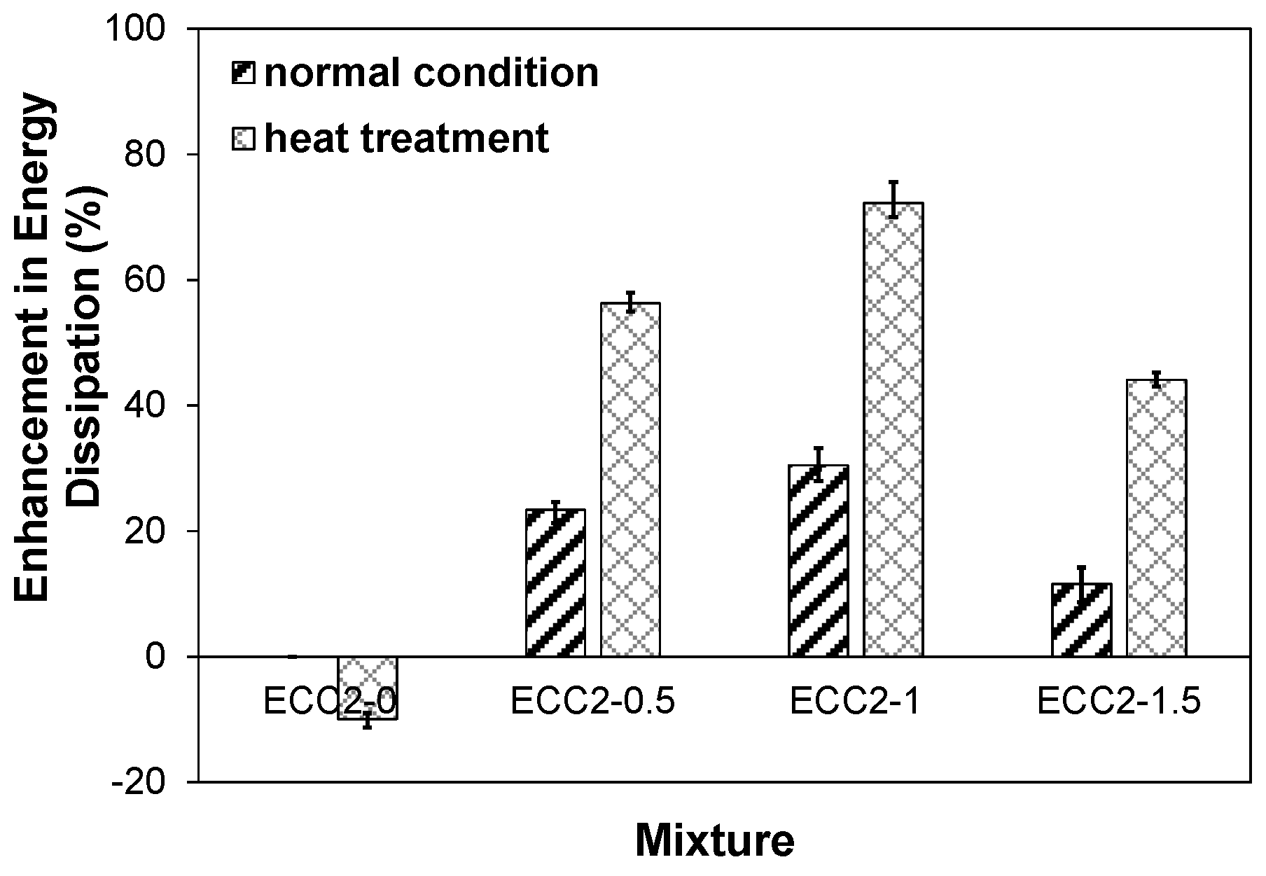
Heating the composite specimens by up to 150 °C led to the formation of multiple hairline cracks of less than 10 µm in width at the front surface of the specimen, as shown in Figure 10a. The heat treatment also led to strength degradation in the ECC specimens incorporating PVA fibers due to the melting of the fibers in the proximity of the heating nozzle, as shown in Figure 10b. Figure 11 exhibits the accumulated energy dissipated by heat-treated and non-heat-treated ECC specimens. For instance, the energy dissipation capability of the heated ECC2-0 specimens decreased by about 9.9% compared to that of its non-heated counterpart. Conversely, the hybrid SMA-PVA fiber-reinforced specimens displayed different performance after the heating process, as demonstrated in Figure 11. For example, the energy absorption capacity of the heated ECC2-0.5, ECC2-1, and ECC2-1.5 specimens increased by about 20.1%, 32%, and 26.56% compared to that of its non-heated counterparts, respectively. This can be ascribed to the shape memory effect of the heated SMA fibers, which led to a local pre-stressing effect of the specimens, consequently enhancing its energy dissipation capability. This highlights the crack arresting capability of SMA fibers in concrete structures, even when affected by high temperature.
4. Numerical Simulation
Numerical simulation and analysis were carried out using the commercial finite element (FE) ABAQUS/Explicit software [35]. This tool incorporates various constitutive models for concrete, including the Concrete Damage Plasticity (CDP) and Drucker/Prager (DP) models.
As per Tahmasebinia [36], the DP model can better simulate the behavior of ductile concrete, especially under low-velocity impact loading compared to Brittle-Cracking models. While Li and Zhang [2] demonstrated the effectiveness of simulating the dynamic behavior of cementitious materials under impact loading using the CDP Model. In the present study, both the CDP and DP models were utilized. Their effectiveness in modeling the behavior of HECC-SMAF composite under impact loading was explored and compared with the experimental results.
4.1. Constitutive Models of Concrete
4.1.1. Concrete Damage Plasticity Model
The Concrete Damage Plasticity (CDP) proposed by Lubliner et al. [37] and Lee and Fenves [38] was used. The CDP model assumes isotropic damage and is suitable for applications in which the concrete is subjected to arbitrary loading conditions, such as cyclic loading. It accounts for degradation of the elastic stiffness created by plastic straining that takes place in tension and compression, and for stiffness recovery effects under cyclic loading [35].
Plasticity and damage are the main phenomena that characterize the nonlinear behavior of cementitious materials. Strain softening, progressive deterioration, and volumetric expansion are the major phenomena that describe the plastic performance of concrete. These phenomena lead to the degradation of strength and stiffness of cementitious materials [37,39,40]. Similarly, the damage is characterized by the reduction of stiffness. A scaled isotropic damage model from the continuum damage mechanics is introduced in ABAQUS (2012). This model describes the stiffness degradation under uniaxial loading as per Equation (1):
where σ is the stress, d is the damage factor, which represents the elastic stiffness degradation and has values in the range between 0 (undamaged) to 1 (fully damaged). E0 is the initial (undamaged) elastic stiffness, while ε and εpl are the total strain and plastic strain, respectively. If no damage is considered in the concrete (d = 0), then Equation (1) can be reduced to Equation (2) as follows:
Stiffness degradation models are classified into elastic degradation models and plastic degradation models according to the presence of plastic strain [37]. The elastic degradation models are represented by the total strain, implying that no plastic strain exists (i.e., = 0, where is the plastic strain with stiffness degradation). In this case, Equation (1) can be modified as follows:
where ε is the total strain. On the other hand, plastic degradation models have been presented to overcome the problems associated with elastic degradation models [37]. Through the plastic degradation models, the stiffness degradation deals with the plastic deformation instead of the total deformation as in the case of elastic models. It means that, after damage, plastic strain still exists (i.e., ≠ 0). According to the aforementioned approach, Equation (1) can be rewritten in the form of Equation (4):
4.1.2. Drucker-Prager Model
The DP model is a plasticity model that describes the behavior of granular materials in which the yield behavior is affected by the equivalent pressure stress [41]. It also takes into consideration inelastic deformations that may be associated with frictional mechanisms, such as sliding of particles across each other [35]. Furthermore, it has the ability to describe the hardening and softening behavior of cementitious materials [42]. A Drucker–Prager failure criterion can be presented in the form of Equation (5):
where J2D and J1 are respectively the second and first invariant of stress deviator. θ is a friction parameter which depends on the plain concrete strength, fco. Function f(K) relates to Lode’s angle, which combines the second and third invariant of deviatoric stress (termed as J3D). It takes into consideration the variation of shear strength of concrete for different load paths and a given hydrostatic pressure and demonstrates the shape of failure function in the deviatoric plane. It can be estimated as shown in Equation (6):
The hardening-softening parameter (κ) can be determined using Equation (7):
where σc is the uniaxial compression stress carried by concrete.
4.2. Simulation Technique
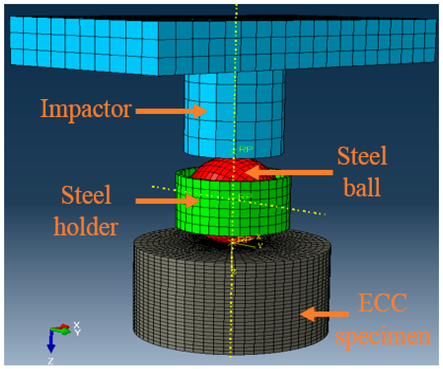
Three-dimensional finite element models of the tested ECC specimens were constructed in ABAQUS/Explicit solver [35]. The cylindrical ECC specimen, spherical steel ball, hollow steel ring holder, and steel drop weight were modeled using their actual dimensions in the experimental test setup. The drop weight was modeled as a prismatic bar with a cylindrical head, as shown in Figure 12. The different ECC specimens were modeled using 8-noded hexagonal solid elements (C3D8R), which is commonly used in the simulation of impact behavior in the ABAQUS [35] library. A sensitivity analysis was conducted to determine an optimum number of elements. The problem was solved with increasingly finer mesh size, and the analysis was assumed to be optimum when the numerical response nearly matched the corresponding experimental data.
4.3. Damage Criterion
Since there is no material model for ECC composites in ABAQUS, the CDP and DP material models were tested as concrete material models to capture the ductile behavior of ECC. Also, the Damage Initiation Criterion and Element Deletion options [35] were utilized in these models for defining the material’s tensile failure criterion [43]. The uniaxial compressive behavior of ECC is characterized by the stress-strain relationship presented by Saenz [44] as follows:
where σc and εc are the compressive stress and strain, respectively. σp and εp are the maximum stress and its corresponding strain, which were evaluated experimentally in this study and considered to be the compressive strength fc’ (MPa) and 0.002, respectively. Furthermore, the elastic modulus (E0) and Poisson’s ratio (ν) of the ECC material were estimated experimentally, as shown in Figure 4a,b.
On the other hand, the problem in the case of uniaxial tension involves tensile cracking. The tension stiffening is defined according to Tao et al. [45], with linear uniaxial tensile stress for the ECC up to the reaching of the tensile strength assumed to be 0.1 of fc0. The softening response is then defined by means of fracture energy GF depending on the uniaxial compressive strength fc0 and the maximum coarse aggregate size d0. The fracture energy is defined as the energy required to create a unit area of the stress-free crack surface, which is size independent, instead of the descending branch of the stress-strain curve, which is size dependent [46]. Accordingly, the stress-crack opening displacement relationship proposed by Hordijk [47] is utilized:
where wt is the crack opening width, wcr is the crack opening width at tensile stress failure, σt is the tensile stress normal to the crack direction, ft is the uniaxial tensile strength, and c1 and c2 are constants determined from tensile tests of ECC. The CEB-FIB [48] model is used in this paper to estimate ft and GF:
where da is the maximum aggregate size. da is assumed to be zero in this study since no coarse aggregate was utilized. Once the stress-crack opening displacement relationship is known, the stress-strain relationship can be determined for each element. Pertinent ECC material parameters, including compressive strength, density, and tensile behavior, were implemented in the models using actual corresponding experimental values shown in Table 3. Also, the constitutive parameters of the CDP and DP models, such as dilation angle Ψ (ranges between 36° and 40°), plastic potential eccentricity e (recommended value e = 0.1), stress ratio fbo/fco (ratio between the compressive strength in bi-and uni-compression stress field, respectively), shape of the loading surface Kc, and viscosity parameter V, were estimated based on the recommended range of values by the ABAQUS manual [35] and Kmiecik and Kaminski [49].
4.4. Initial and Boundary Conditions
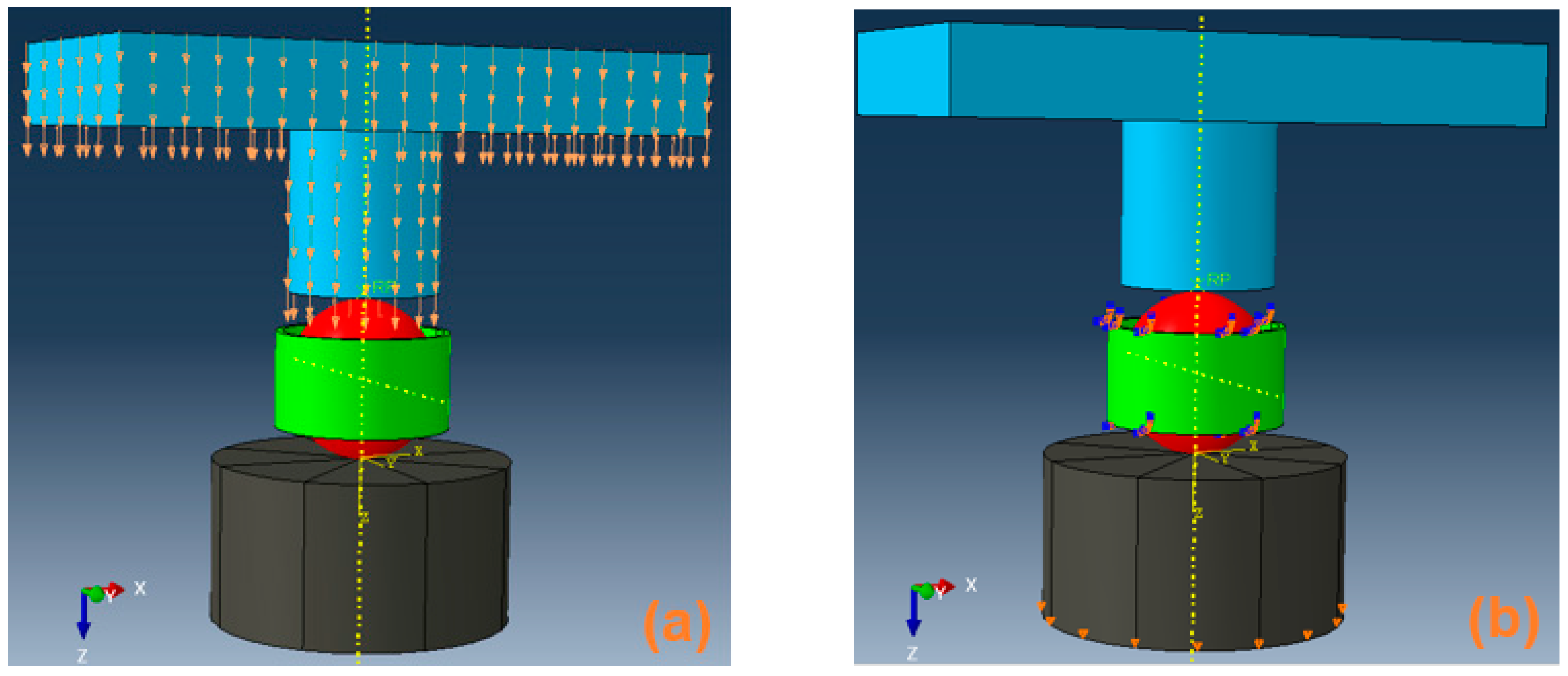
Two types of conditions were adopted in the modeling procedures, initial and boundary conditions. The initial condition was assigned to the impactor with a velocity of 1.38 m/s when it touches the spherical ball, as displayed in Figure 13a. All the nodes of the impactor and spherical ball could move only in the Z-direction. All the nodes of the hollow steel ring were prevented from movement in all directions, while all the nodes of the lower base of the ECC specimen were prevented from moving in Z-direction, as shown in Figure 13b.
5. Analysis of Results and Discussion
Dynamic analysis in this numerical simulation was conducted for the first, second, and third free drops of the impactor. Thereafter, the accumulated damage, due to multiple impacts, was presented. Numerical predictions were compared to the corresponding experimental data as discussed below.
5.1. Effect of Mesh Density on Model Accuracy
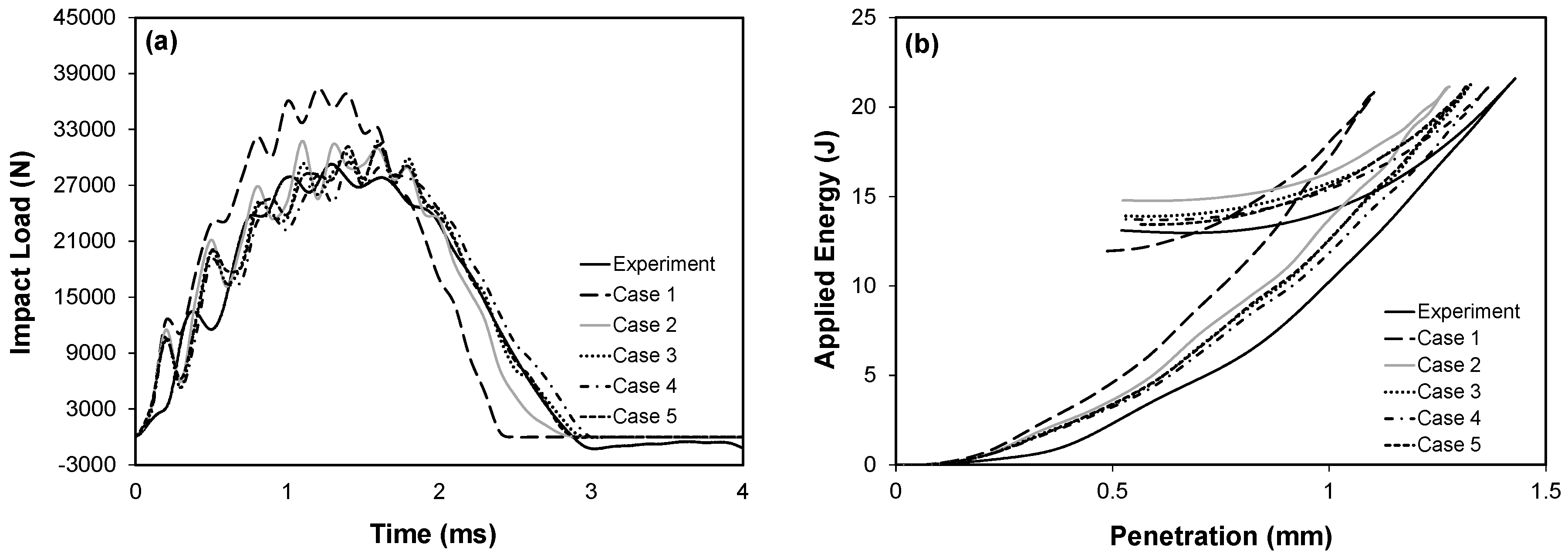
To investigate the effectiveness of utilizing different mesh densities on model accuracy, the load-time history and applied energy-penetration curves resulting from the numerical analysis were compared with the corresponding results obtained from the experimental investigation as portrayed in Figure 14a,b. Five different meshing densities were examined ranging from very fine to coarse. Table 4 displays the number of elements utilized in each case and the ratio between the results obtained from the finite element analysis (FEA) and the corresponding experimental results. It can be observed that as the number of elements increased, the shape of the predicted curves became smoother and progressively converged toward the experimental behavior. Cases 1 and 2 were far from the experimental curve. Conversely, cases 3 and 5 almost gave similar results to the experimental curves. Case 4 achieved the closest prediction of the experimental results. Based on the results in Table 4, the near optimum number of elements utilized in simulating the ECC specimens was 15,180 elements. Since the spherical steel ball, holder steel ring, and drop weight were considered rigid, their element sizes had no significant effect on the solution.
5.2. Energy-Penetration Behavior
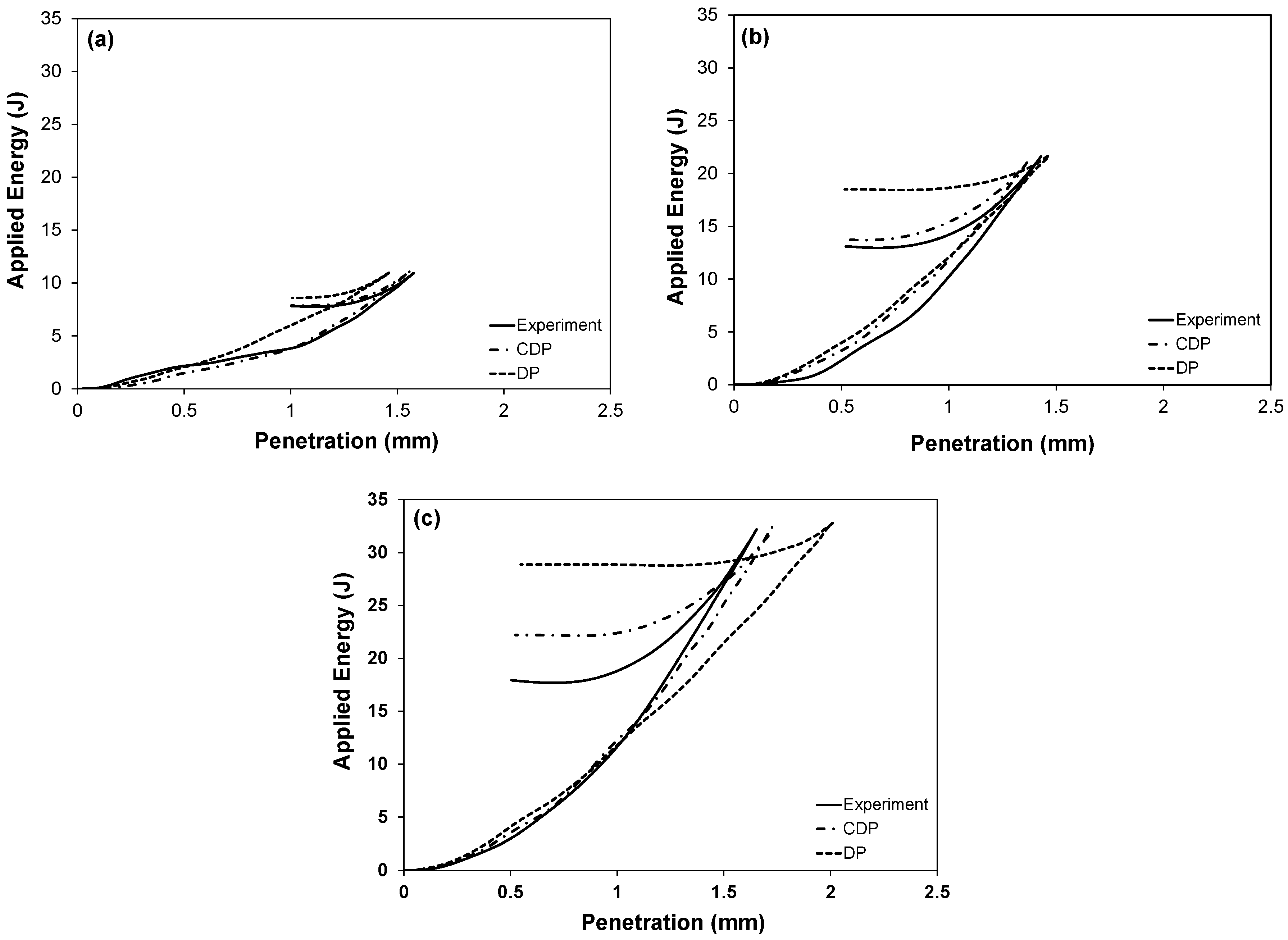
Dynamic loading on structures is accompanied by a large transfer of mechanical energy. To numerically explore the behavior of structural elements under impact loading, consideration of the energy balance should be the first step [28]. In the FEA, the impactor and the concrete element were presented as a single mechanical system. Before impact, the drop weight only had kinetic energy, while during impact, the drop weight slowed down significantly (lost a substantial part of its kinetic energy) due to the energy dissipation capability of the concrete element. Figure 15 presents the experimental and numerical applied energy-penetration depth curves for the ECC specimens at different drop levels. It can be observed that the CDP and DP models could closely estimate the experimental behavior of the ECC specimens under impact loading.
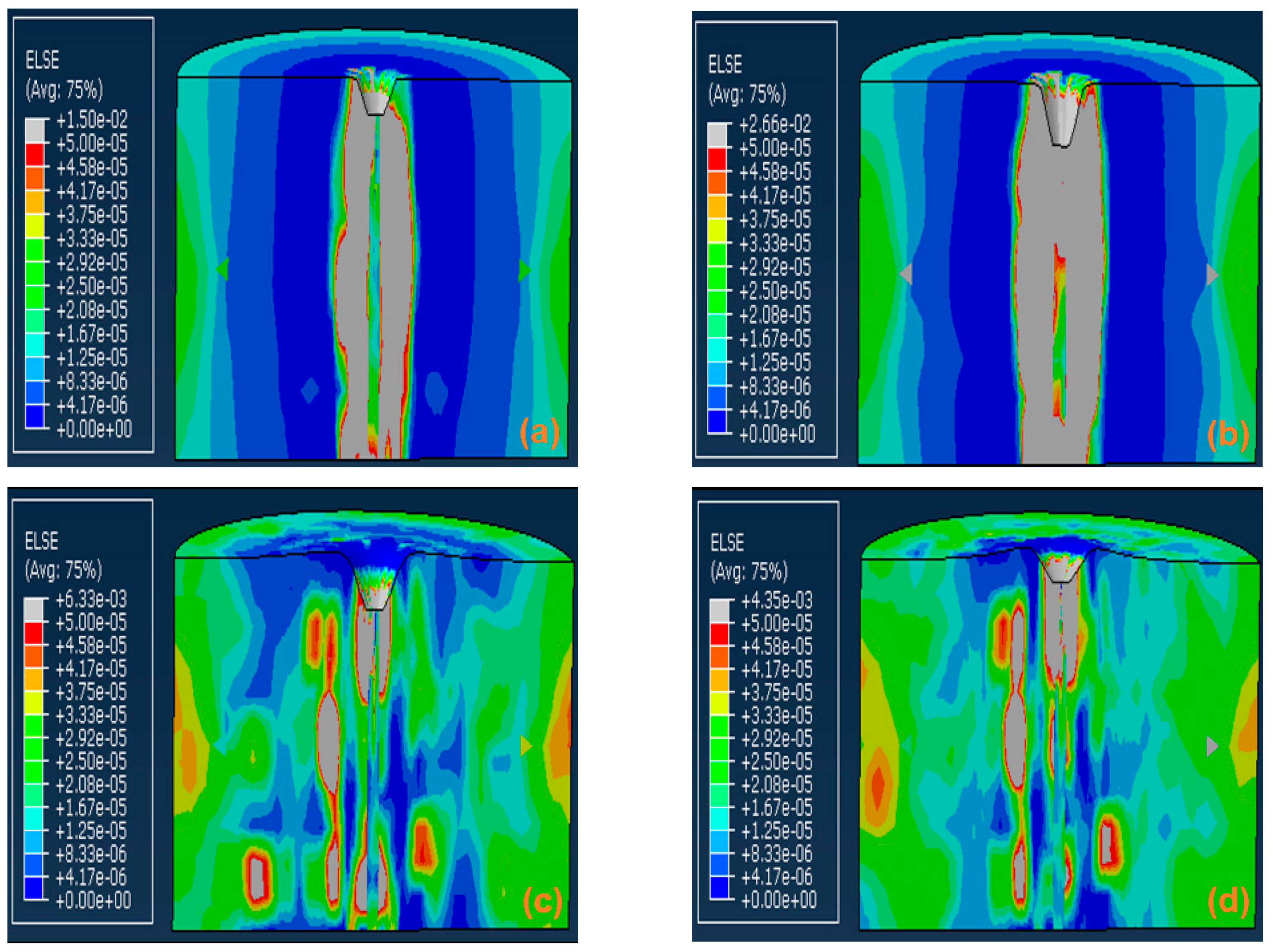
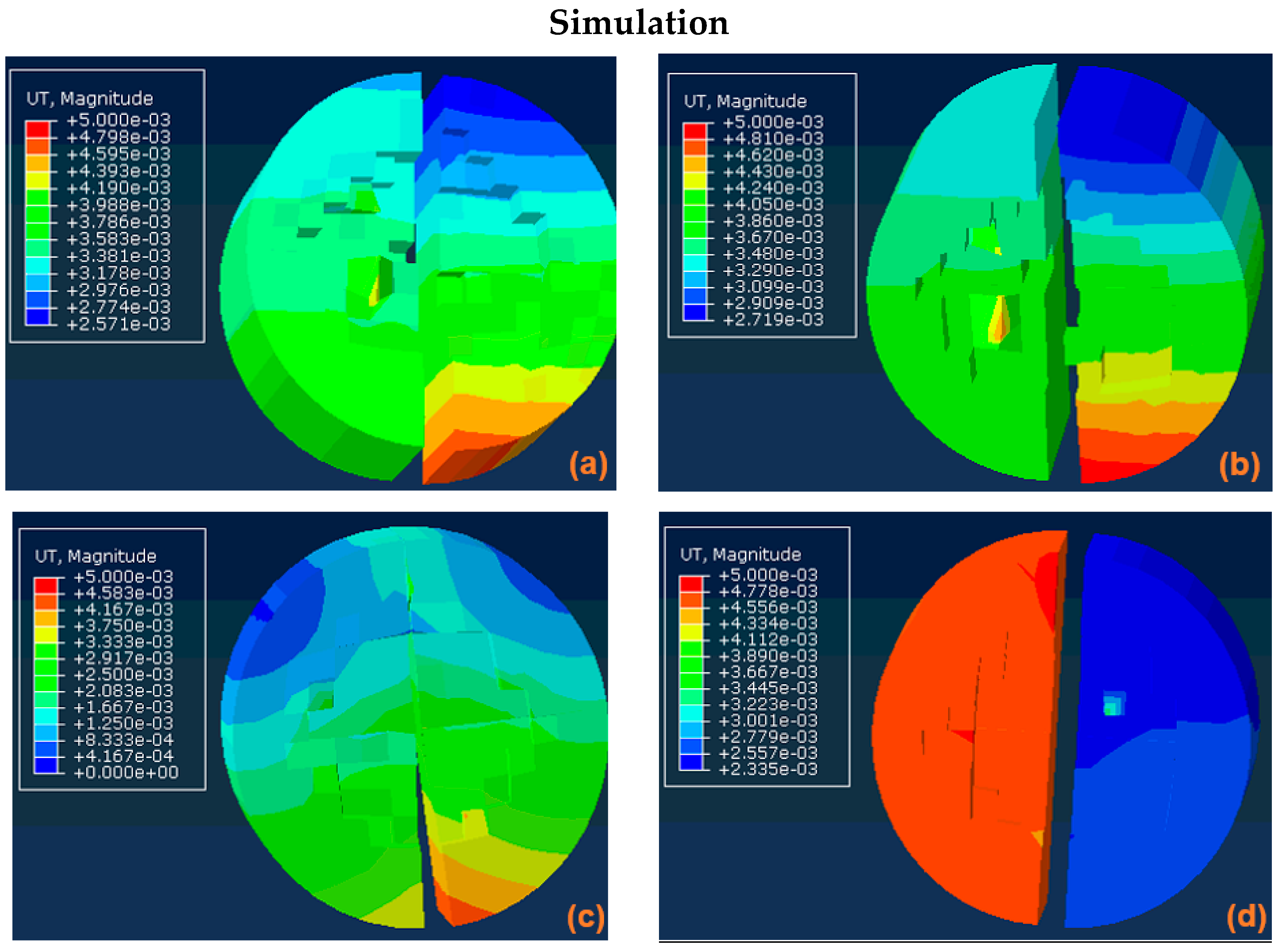
Table 5 reports the experimental and numerical results for all tested specimens. Although the DP model exhibited good estimation of the applied energy at the first impact, the CDP model generally displayed better performance in simulating experimental results at higher impact levels. Figure 16 displays the strain energy magnitude propagated through the ECC specimens due to impact loading at different time intervals along with that remaining in the specimen after impact. It can be observed that the propagated energy kept increasing through the specimen during the impact process, while it was partially reversed (dissipated) upon removal of the load. The amount of applied energy which remained or dissipated in the system depended mainly on the energy dissipation capability of the tested material.
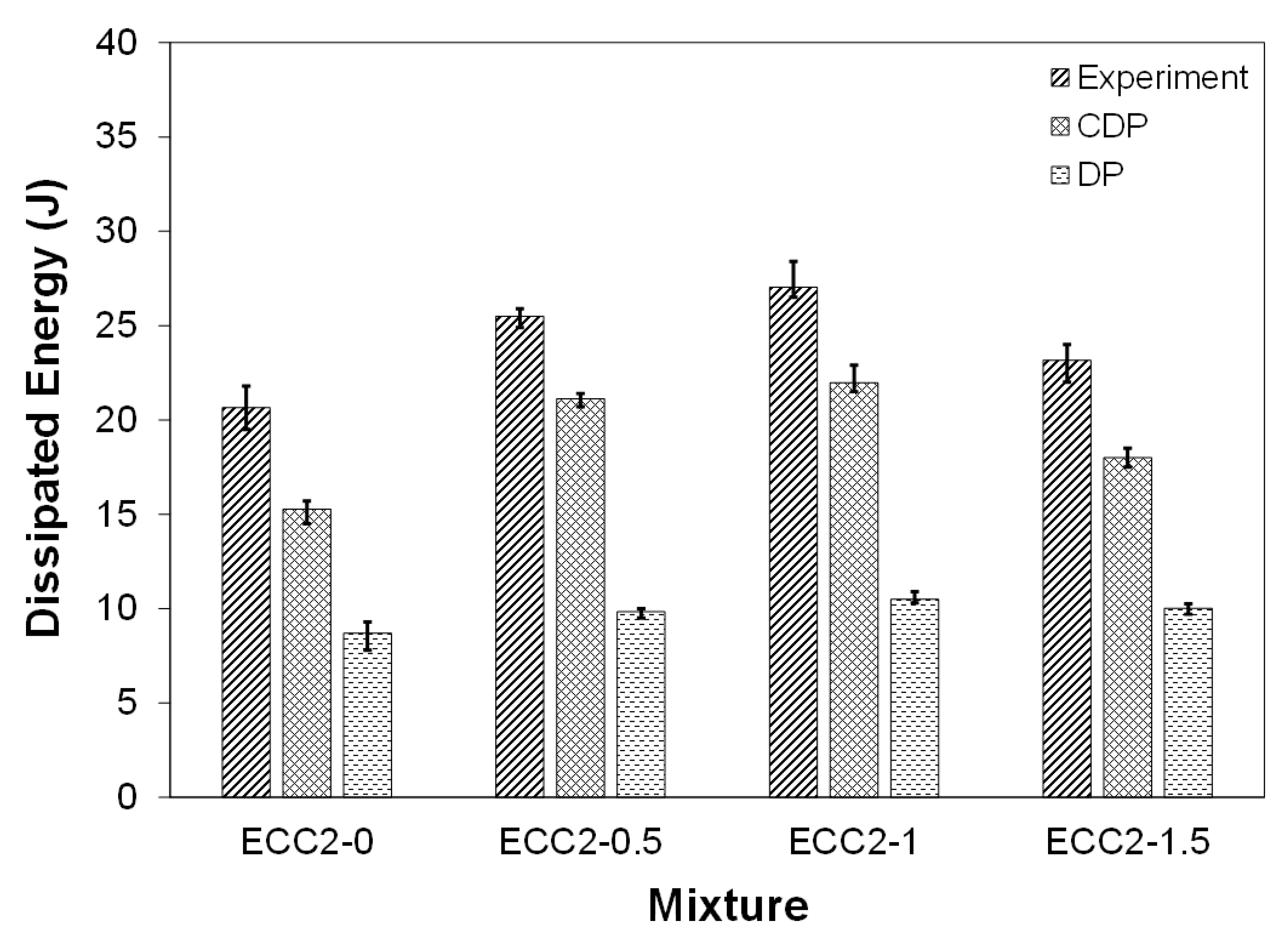
Figure 17 illustrates the total energy dissipated through all impact levels for the various ECC specimens. It can be observed that the numerical and experimental values of dissipated energies were in good agreement. During experimental testing, cracks were usually captured when their width was sufficiently developed, while in numerical simulations, they could be detected at earlier stages. This could result in estimating numerical dissipated energies that were lower than their corresponding experimental values. Also, it can be observed that the total energy dissipated through the ECC specimens using the CDP model was in better agreement with the experimental results compared to that of the DP model. For instance, the total energy dissipated through the ECC2-0, ECC2-0.5, ECC2-1, and ECC2-1.5 specimens using the CDP model was 24.4%, 17.3%, 18.8%, and 21.9% lower than that of the experimental results, respectively. However, using the DP model, the total energy dissipated was 58.0%, 61.5%, 61.1%, and 56.6% lower than the corresponding experimental results, respectively.
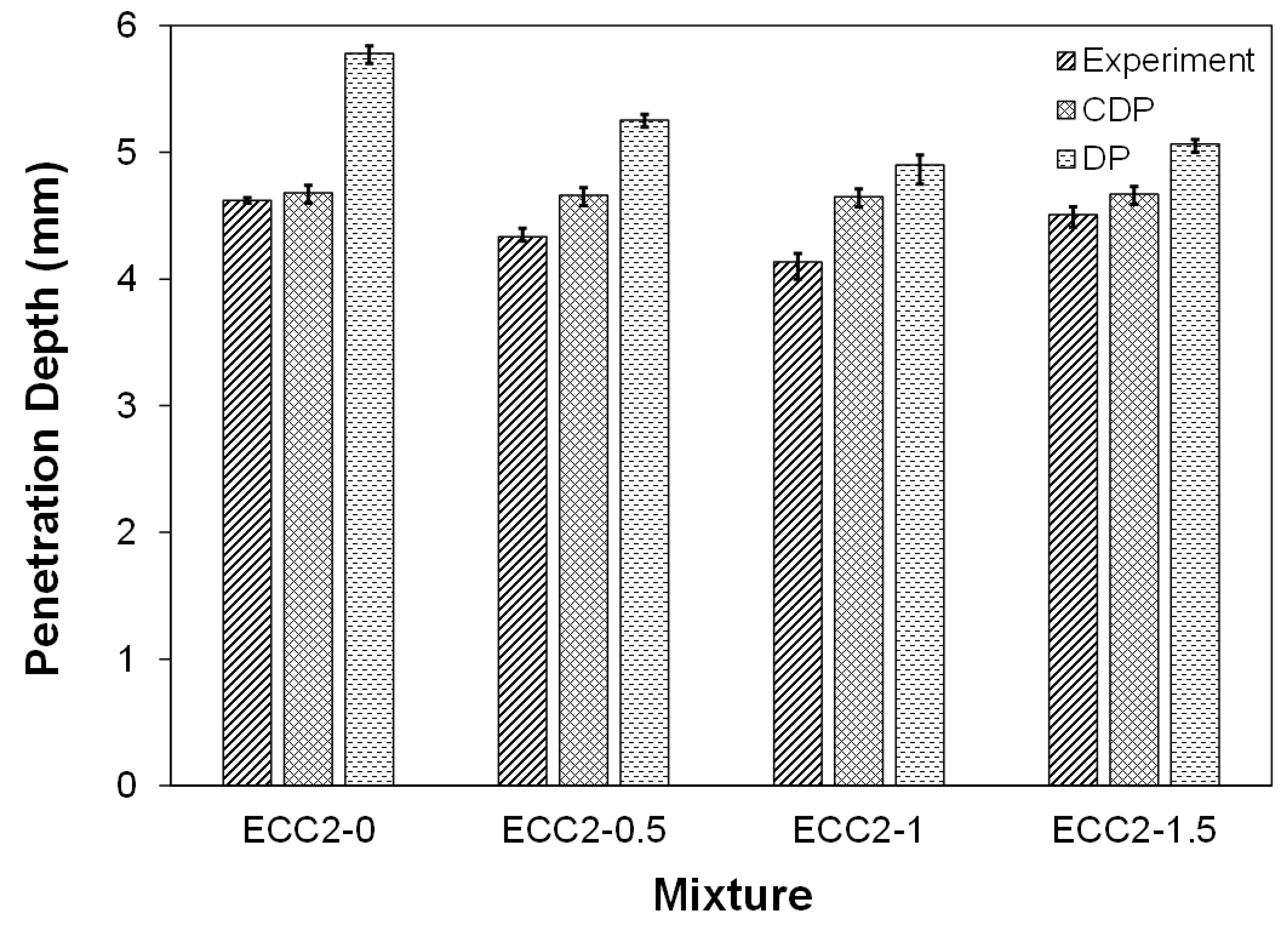
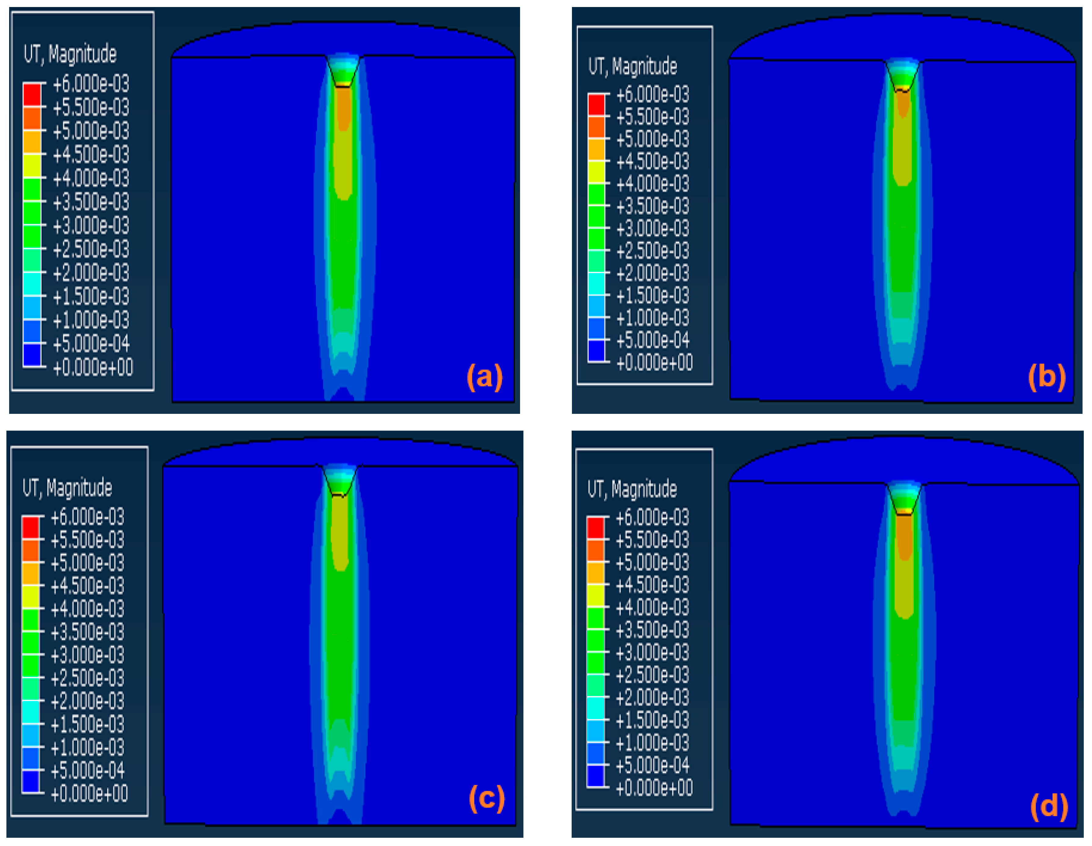
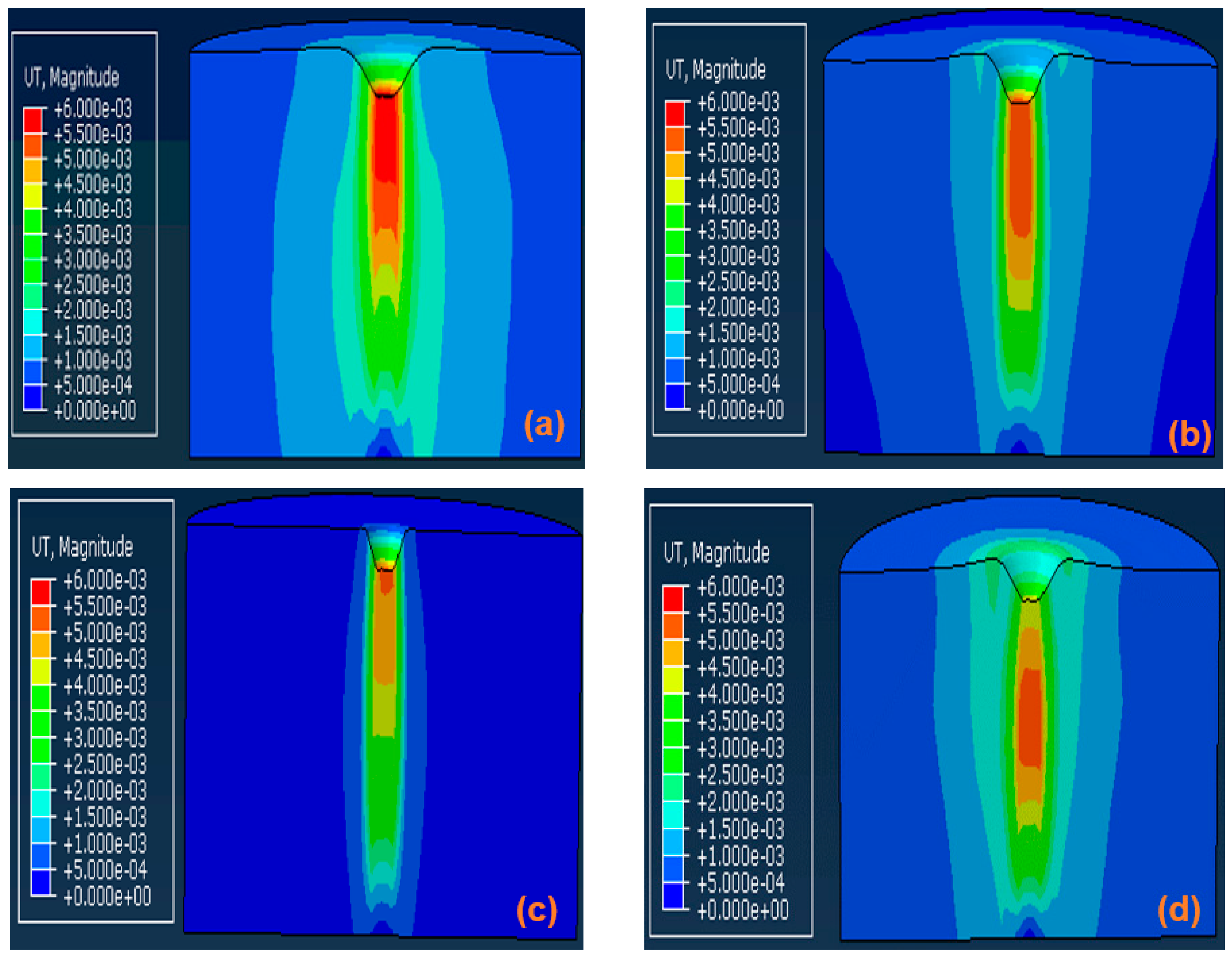
Similarly, the numerically estimated penetration depth of the different ECC specimens under multiple impacts was in good agreement with corresponding experimental observation, as shown in Table 5. Figure 18 displays the accumulated penetration depth measured through the different ECC specimens due to multiple impacts. Furthermore, Figure 19 and Figure 20 show the total numerically estimated penetration depth using the CDP and DP models, respectively. It can be observed that the CDP model was more accurate than the DP model in predicting the penetration depth upon multiple impacts. For instance, the total penetration depth determined by the CDP model for the ECC2-0, ECC2-0.5, ECC2-1, and ECC2-1.5 specimens was 1.1%, 7.2%, 12.1%, and 3.7% higher than the experimental results, respectively. However, the total penetration depth estimated using the DP model was 25.1%, 21.2%, 18.7%, and 12.6% higher than the experimental results, respectively.
5.3. Impact Load-Time History
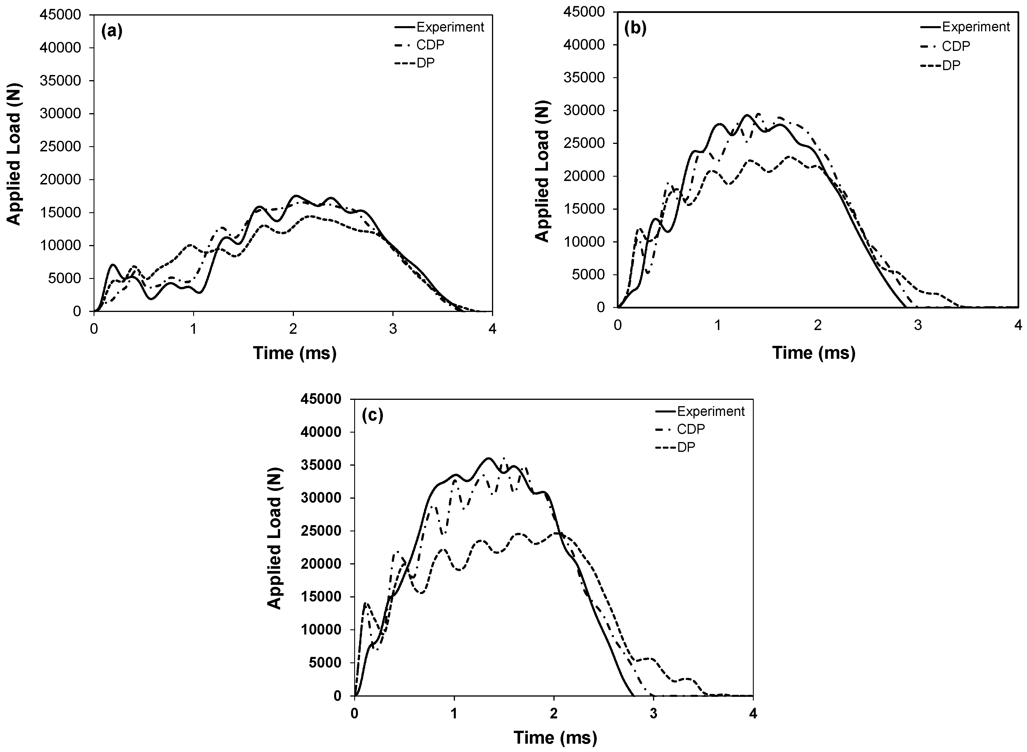
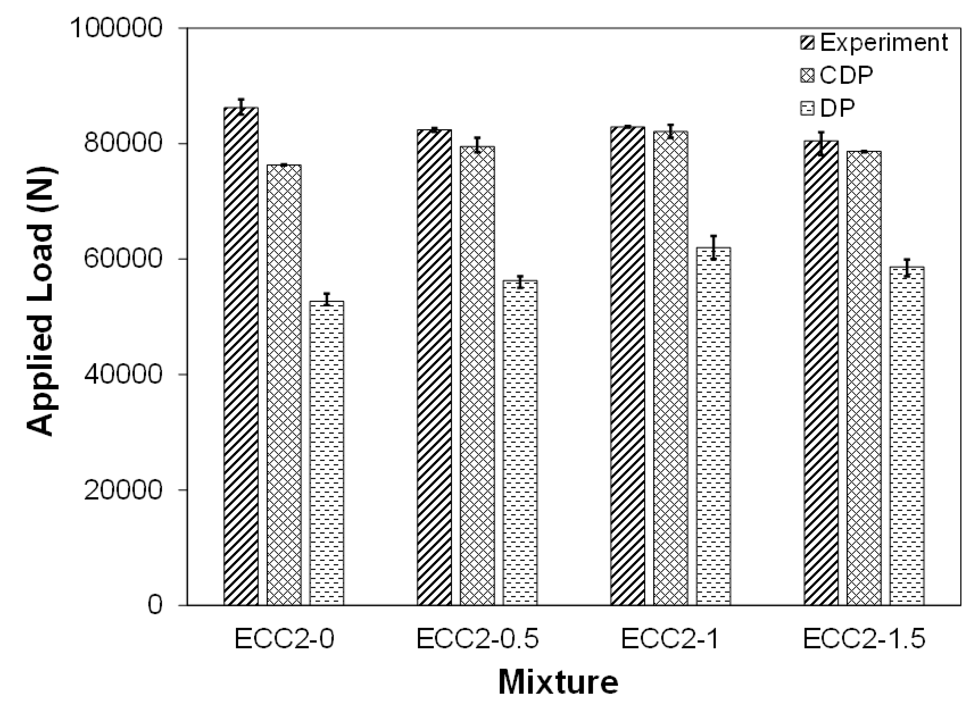
The ductility features imparted into the CDP and DP models enable simulating the behavior of ECC materials under dynamic loading close to experimental findings, as shown in Figure 21, with the CDP model exhibiting superior performance. The tolerance in the applied load estimated using the DP model was about four times that of the CDP model compared to actual experimental data. For instance, as displayed in Figure 22, the accumulated impact load applied on the ECC2-0, ECC2-0.5, ECC2-1, and ECC2-1.5 estimated using the CDP model was 11.6%, 3.5%, 1.0%, and 2.2% lower than the corresponding experimental data, respectively, while that estimated by the DP model was 39.6%, 31.7%, 25.2%, and 26.9% lower than the experimental results, respectively. The difference in numerical accuracy can be attributed to the fact that the CDP model is constructed based on the two main failure mechanisms of concrete: tensile cracking and compressive crushing. The evolution of yield surfaces in concrete is controlled by two hardening variables, which causes failure under tensile and compressive stresses simultaneously. While the DP model is based on the same criterion, only one of the two main failure mechanisms can be assigned for the material during the simulation, which affects its overall performance.
6. Failure Criterion
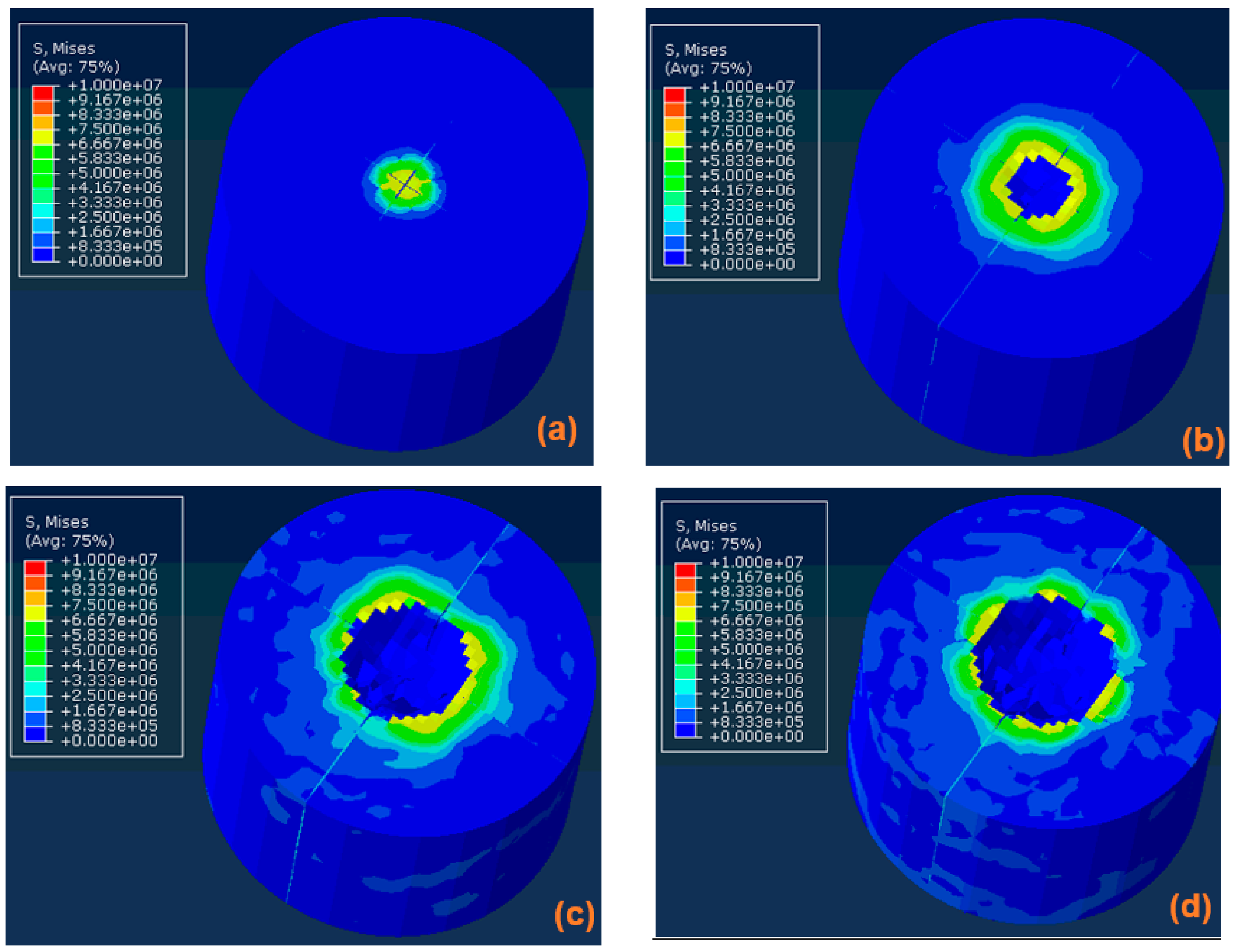
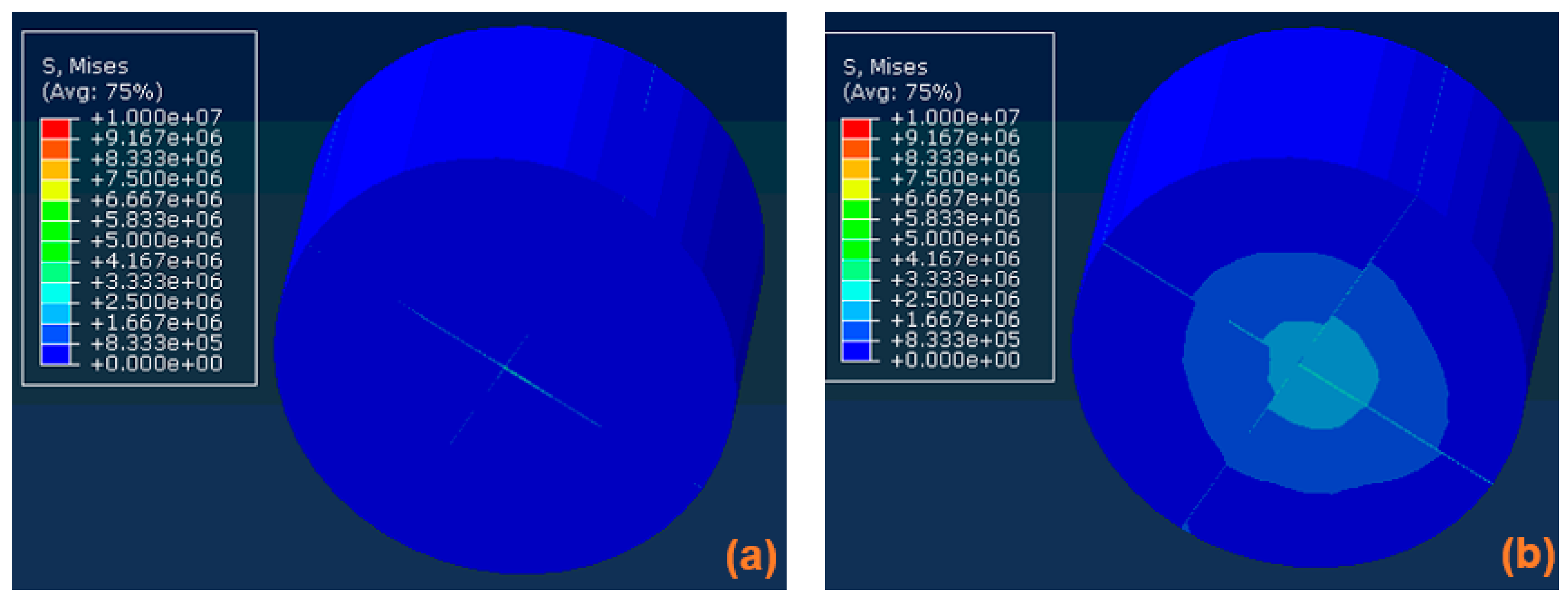
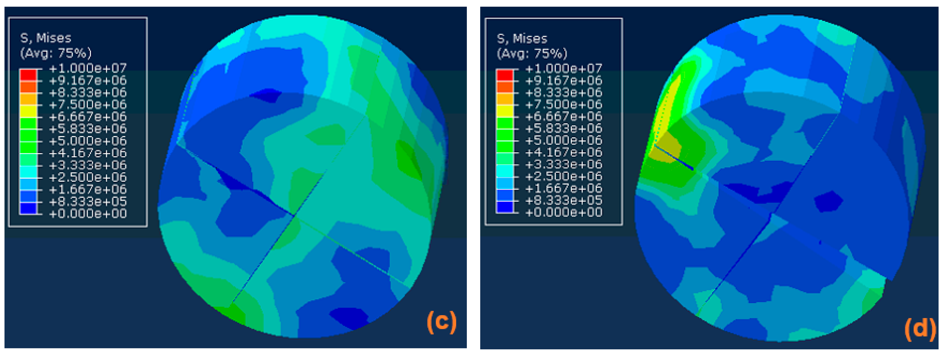
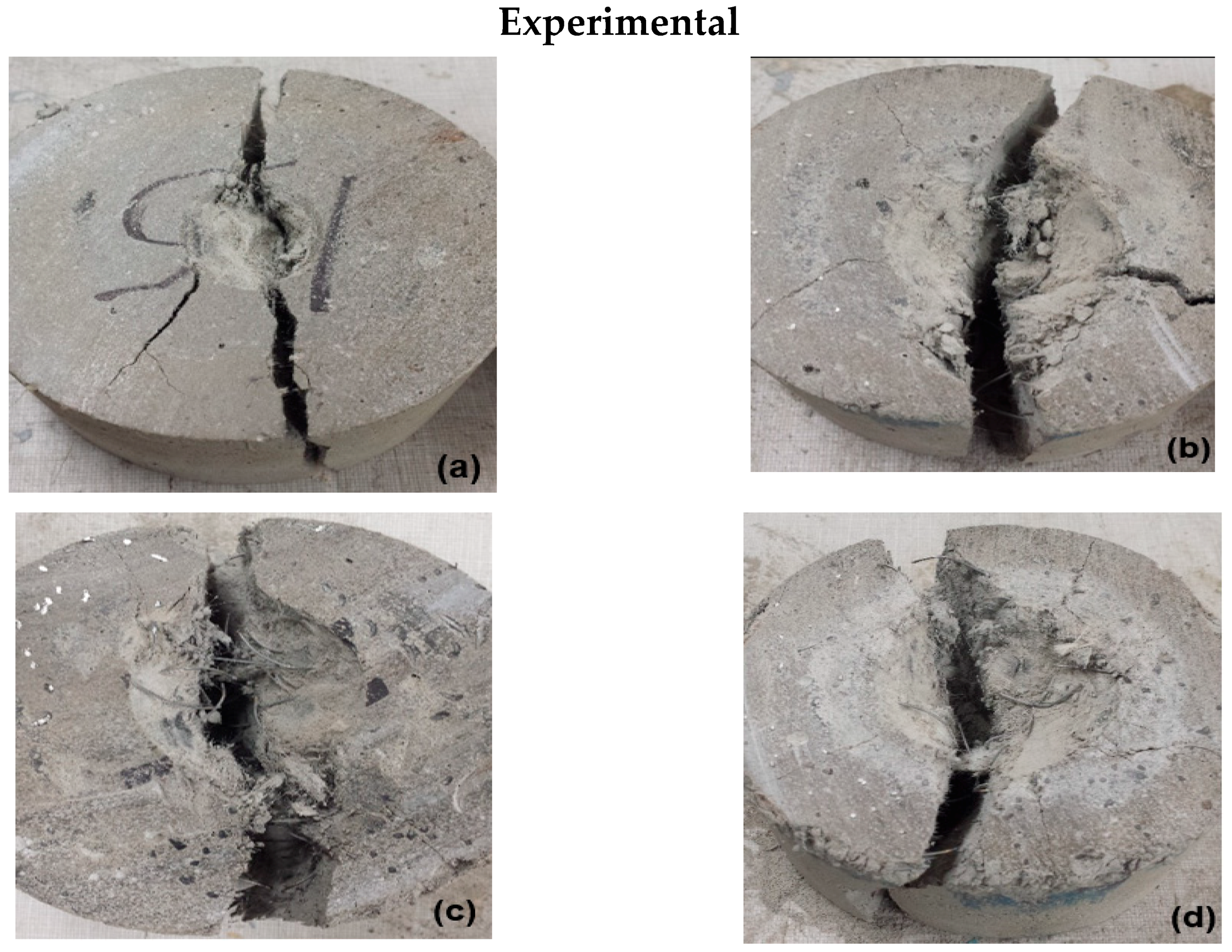
A key benefit of the numerical simulation is the ability to capture when and where the first crack is initiated, which is experimentally more challenging. Figure 23 and Figure 24 display the stress distributions through the ECC specimens outlined via the numerical simulations. Maximum and minimum principal stresses were illustrated on the upper and lower surfaces of the different ECC specimens. It was observed that the stress distributions in the developed models using ductile modeling techniques, such as the CDP or DP models, can give realistic results of the actual crack propagation under impact loading. Figure 25 illustrates a comparison between the experimental and numerical simulation failure criterion of different ECC specimens under impact loading. The differences in the stress distribution between the experimentally tested and simulated specimens can generally be attributed to the fact that the tested specimens were made from a rather heterogeneous material, while a homogeneity assumption was made in the simulation process. This could lead to variation in the crack propagation path. The stress distribution in the ECC elements was globally distributed rather than local. This can be observed through the impulsive waves generated due to impact loading on all surfaces of the ECC specimens. Furthermore, it was observed that the tensile stresses were propagated at the upper surface of specimens around the circumferential edge of the impacting ball (Figure 23). Yet, the compressive stresses were generated through the specimen under the impacted area. These compressive stresses were transferred into tensile stresses when the elastic wave reflected at the distal face. Under impact loading, the tensile stresses in concrete structures cannot be avoided.
7. Validation of Numerical Model
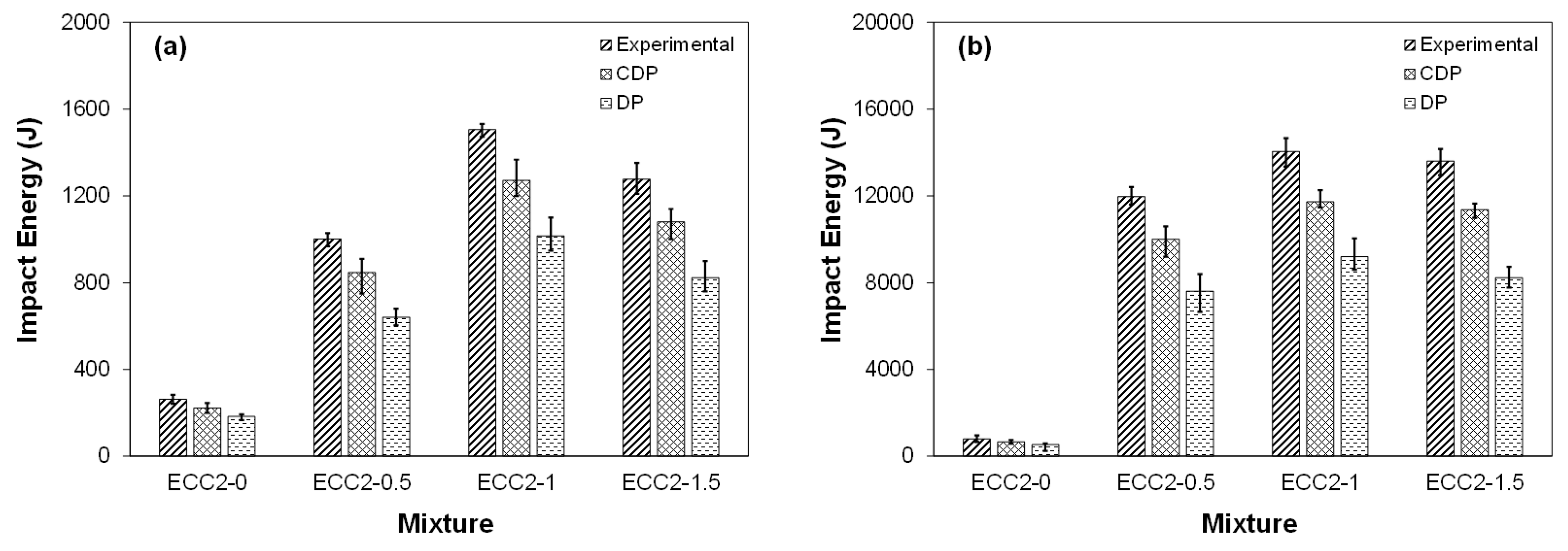
The numerical models were first used to evaluate the applied impact energy required to achieve crack initiation and failure of the tested specimens, and their results were subsequently compared to that experimentally acquired in a recent study by Ali et al. [6]. Figure 26a,b illustrate the experimental and numerical values of the impact energy sustained until crack initiation and final fracture of the ECC specimens, respectively. It can be observed that there was a reasonable agreement between the numerical predictions and experimental results. The numerically estimated results using the CDP and DP models were 18.7% and 39.2% lower than the corresponding experimental data, respectively. For instance, per the CDP model, the sustained impact energy until first crack initiation and final fracture for the ECC2-0, ECC2-0.5, ECC2-1, and ECC2-1.5 specimens were lower than the experimental values by 15.5%, 16.2%, 18.7%, and 17.1% and 16.3%, 17.4%, 16.7%, and 18.2%, respectively. Likewise, the sustained impact energy until first crack initiation and final fracture of the ECC2-0, ECC2-0.5, ECC2-1, and ECC2-1.5 using the DP model was lower than the experimental data by about 30.2%, 36.1%, 32.5%, and 35.5% and 32.3%, 36.5%, 34.5%, and 39.2%, respectively. The CDP model outperformed the DP model in evaluating the fracture energy of ECC specimens under impact loading, which supports earlier discussion. Differences between the experimental and numerical results can be ascribed to the inability of the simulation to model how the fibers were pulled out along with approximations related to the definition of materials parameters.
The various hybrid composite HECC-SMAF specimens achieved superior impact resistance to that of the control PVA-ECC specimens. This is ascribed to the higher energy dissipation capability and pull-out resistance of SMA fibers compared to that of PVA fibers, requiring more energy before fracture of the specimens. The ECC2-1 specimen exhibited superior impact resistance compared to that of all other ECC specimens, which was observed both experimentally and numerically. Higher fiber dosage beyond 2% PVA and 1% SMA by volume fraction led to tensile strength and impacted resistance degradation due to fiber clustering and increased porosity, as evidenced elsewhere by Ali et al. [6].
8. Conclusions
Experimental testing and numerical simulations were carried out in the present study to investigate the behavior under impact loading of a novel composite endowed with strain recovery, which is made of an engineered cementitious composite incorporating hybrid SMA and PVA short fibers. Impact loading was conducted at different drop levels using a drop weight impact test, and numerical simulations of the composite’s impact behavior were performed. The following conclusions can be drawn based on this research:
- The tensile properties of the ECC composite were generally enhanced owing to SMA fiber addition. All ECC mixtures achieved a tensile strain of up to 8%. Among the tested mixtures, the composite incorporating 2% PVA and 1% SMA fibers achieved the highest tensile properties and impact resistance.
- Generally, the impact resistance of the composite was improved owing to SMA fiber addition. Upon multiple impacts, the energy dissipation capability of the HECC-SMAF composite was increased by about 23.39%, 30.43%, and 11.53% owing to SMA fiber addition of 0.5%, 1%, and 1.5% by volume fraction, respectively, compared to that of the ECC specimen incorporating 2% PVA fibers alone.
- The impact penetration depth tended to decrease upon SMA fiber addition. For instance, the ECC2-0.5, ECC2-1, and ECC2-1.5 specimens had 6.3%, 10.1%, and 2.6% lower penetration depth compared to that of the control PVA-ECC specimen, respectively.
- The heat treatment process led to the melting of the PVA fibers with the associated loss in mechanical properties. Yet, the heat treatment stimulated the SMA fibers to locally prestress the composite’s matrix owing to its shape memory effect. Consequently, an overall enhancement in the energy absorption capacity of the heated HECC-SMAF hybrid composite over that of its non-heated counterpart was observed.
- The superior impact performance of the hybrid composite and similar composites [50] make such novel materials the strong contenders for constructing protective structures, with a potential to enhance the safety of critical infrastructure assets against explosions and impact events.
- Plasticity models, coupled with the add-erosion option and maximum principal strain, were appropriate for simulating the behavior of the ECC composite under impact loading.
- The numerical simulation results using the Concrete Damage Plasticity were in closer agreement with the corresponding experimental data than that of the Drucker/Prager model in terms of energy dissipation capability and maximum penetration depth. The numerically estimated results in terms of the energy dissipation ability using the CDP and DP models were 24.4% and 61.5% lower than that of the corresponding experimental data, respectively, while it was higher than that of the corresponding experimental data by 12.1% and 25.1% in terms of the total penetration depth, respectively.
- Generally, the stress distribution, crack propagation, and failure criterion of the numerically simulated ECC specimens were in good agreement with the experimentally observed behavior of the ECC specimens under impact loading. However, the tolerance in the applied impact load evaluated using the DP model was about four times that of the CDP model compared to that estimated experimentally.
- This study demonstrates the feasibility of using numerical simulation to reasonably predict the behavior of the hybrid composite developed in this study under impact loading. The model can be further enhanced to capture additional aspects related to the fiber type, dosage, strain rate, and other relevant parameters that were not within the scope of the current study. Developing a comprehensive and robust model can save time, effort, and cost associated with laborious experimental testing.
Author Contributions
M.L.N. developed the scientific concept of the study and its plan. M.L.N. also wrote the final version of the manuscript. M.A.E.M.A. conducted the experimental testing and numerical modeling and wrote the initial draft of the manuscript.
Funding
This research was supported by a Discovery Grant awarded to the first author by the Natural Science and Engineering Research Council of Canada (NSERC).
Conflicts of Interest
The authors have no explicit or implicit conflict of interest of any kind related to this research.
References
- El-Tehewy, E.M.; El-Sayed, M.A. The effect of using multi layers of expanded steel mesh on penetration resistance of ferrocement slabs. Int. J. Environ. 2015, 4, 300–308. [Google Scholar]
- Li, J.; Zhang, Y.X. Evaluation of constitutive models of hybrid-fibre engineered cementitious composites under dynamic loadings. Construct. Build. Mater. 2012, 30, 149–160. [Google Scholar] [CrossRef]
- Zollo, R.F. Fiber-reinforced concrete: An overview after 30 years of development. Cement Concr. Compos. 1997, 19, 107–122. [Google Scholar] [CrossRef]
- Li, V.C. On engineered cementitious composites (ECC): A review of the material and its applications. J. Adv. Concr. Technol. 2003, 1, 215–230. [Google Scholar] [CrossRef]
- Soe, T.K.; Zhang, Y.X.; Zhang, L.C. Material properties of a new hybrid fibre-reinforced engineered cementitious composite. Construct. Build. Mater. 2013, 43, 399–407. [Google Scholar] [CrossRef]
- Ali, A.E.M.A.; Soliman, A.M.; Nehdi, M.L. Hybrid-fiber reinforced engineered cementitious composite under tensile and impact loading. Mater. Des. 2017, 117, 139–149. [Google Scholar] [CrossRef]
- Song, P.S.; Hwang, S.; Sheu, B.C. Strength properties of nylon- and polypropylene-fiber-reinforced concretes. Cement Concr. Res. 2005, 35, 1546–1550. [Google Scholar] [CrossRef]
- Li, W.; Xu, J. Mechanical properties of basalt fiber reinforced geopolymeric concrete under impact loading. Mater. Sci. Eng. A 2009, 505, 178–186. [Google Scholar] [CrossRef]
- Yoo, D.-Y.; Banthia, N.; Kim, S.-W.; Yoon, Y.-S. Response of ultra-high-performance fiber-reinforced concrete beams with continuous steel reinforcement subjected to low-velocity impact loading. Compos. Struct. 2015, 126, 233–245. [Google Scholar] [CrossRef]
- Soe, K.T.; Zhang, Y.X.; Zhang, L.C. Impact resistance of hybrid-fiber engineered cementitious composite panels. Compos. Struct. 2013, 104, 320–330. [Google Scholar] [CrossRef]
- Nehdi, M.; Duquette, J. Fibre synergy in hybrid fibre-reinforced self-consolidating concrete. ACI Mater. J. 2004, 101, 508–517. [Google Scholar]
- Nia, A.A.; Hedayatian, M.; Nili, M.; Sabet, V.A. An experimental and numerical study on how steel and polypropylene fibers affect the impact resistance in fiber-reinforced concrete. Int. J. Impact Eng. 2012, 46, 62–73. [Google Scholar]
- Maalej, M.; Quek, S.T.; Zhang, J. Behaviour of hybrid-fiber engineered cementitious composites subjected to dynamic tensile loading and projectile impact. J. Mater. Civil Eng. 2005, 17, 143–152. [Google Scholar] [CrossRef]
- Yang, E.-H.; Li, V.C. Tailoring engineered cementitious composites for impact resistance. Cement Concr. Res. 2012, 42, 1066–1071. [Google Scholar] [CrossRef]
- Wu, H.; Zhang, Q.; Huang, F.; Jin, Q. Experimental and numerical investigation on the dynamic tensile strength of concrete. Int. J. Impact Eng. 2005, 32, 605–617. [Google Scholar] [CrossRef]
- Tai, Y.-S.; Tang, C.-C. Numerical simulation: The dynamic behavior of reinforced concrete plates under normal impact. Theor. Appl. Fract. Mech. 2006, 45, 117–127. [Google Scholar] [CrossRef]
- Teng, T.-L.; Chu, Y.-A.; Chang, F.-A.; Shen, B.-C.; Cheng, D.-S. Development and validation of numerical model of steel fiber reinforced concrete for high-velocity impact. Comput. Mater. Sci. 2008, 42, 90–99. [Google Scholar] [CrossRef]
- Farnam, Y.; Mohammadi, S.; Shekarchi, M. Experimental and numerical investigations of low velocity impact behavior of high-performance fiber-reinforced cement based composite. Int. J. Impact Eng. 2010, 37, 220–229. [Google Scholar] [CrossRef]
- Chin, L.S. Finite Element Modeling of Hybrid-Fiber ECC Targets Subjected to Impact and Blast. Ph.D. Thesis, National University of Singapore, Singapore, 23 January 2007. [Google Scholar]
- Anil, O.; Durucan, C.; Erdem, R.T.; Yorgancilar, M.A. Experimental and numerical investigation of reinforced concrete beams with variable material properties under impact loading. Construct. Build. Mater. 2016, 125, 94–104. [Google Scholar] [CrossRef]
- ASTM Standard. Standard Specification for Portland Cement; ASTM Standard C150/C150M; ASTM International: West Conshohocken, PA, USA, 2015. [Google Scholar]
- ASTM Standard. Standard Specification for Coal Fly Ash and Raw or Calcined Natural Pozzolan for Use in Concrete; ASTM Standard C618; ASTM International: West Conshohocken, PA, USA, 2015. [Google Scholar]
- ASTM Standard. Standard Specification for Chemical Admixtures for Concrete; ASTM Standard C494/C494M; ASTM International: West Conshohocken, PA, USA, 2015. [Google Scholar]
- ASTM Standard. Standard Specification for Wrought Nickel-Titanium Shape Memory Alloys for Medical Devices and Surgical Implants; ASTM Standard F2063; ASTM International: West Conshohocken, PA, USA, 2012. [Google Scholar]
- ASTM Standard. Standard Test Method for Compressive Strength of Cylindrical Concrete Specimens; ASTM Standard C39/C39M; ASTM International: West Conshohocken, PA, USA, 2015. [Google Scholar]
- ASTM Standard. Standard Test Method for Static Modulus of Elasticity and Poisson’s Ratio of Concrete in Compression; ASTM Standard C469/C469M; ASTM International: West Conshohocken, PA, USA, 2014. [Google Scholar]
- Martin, O. Comparison of different constitutive models for concrete in ABAQUS/explicit for missile impact analyses. JRC Sci. Tech. Rep. 2010, 44. [Google Scholar] [CrossRef]
- Murnal, P.B.; Chatorikar, R.N. Impact resistance of steel fiber reinforced concrete. IJRET Int. J. Res. Eng. Tech. 2015, 4, 241–246. [Google Scholar]
- Xiang-yu, C.; Yi-ning, D.; Azevedo, C. Combined effect of steel fibres and steel rebars on impact resistance of high performance concrete. J. Central South. Uni. Technol. 2011, 18, 1677–1684. [Google Scholar] [CrossRef] [Green Version]
- Patel, U.R.; Rathod, J.D.; Chauhan, D.K. Comparative study of engineered cementitious composites and self-compacting engineered cementitious composites on response under impact loading. Int. J. Emerg. Technol. Adv. Eng. 2012, 2, 262–264. [Google Scholar]
- ACI Standard. Measurement of Properties of Fiber Reinforced Concrete; ACI Standard 544.2R-89; ACI Standard: Farmington Hills, MI, USA, 2009; reapproved. [Google Scholar]
- Kim, M.K.; Kim, D.J.; Chung, Y.-S.; Choi, E. Direct tensile behavior of shape-memory-alloy fiber-reinforced cement composites. Construct. Build. Mater. 2016, 102, 462–470. [Google Scholar] [CrossRef]
- Nehdi, M.; Soliman, A. Novel green roofing membrane system made with recycled leftover paint. Green Mater. 2013, 1, 231–241. [Google Scholar] [CrossRef]
- Li, Q.M.; Mines, R.A.; Birch, R.S. The crush behaviour of Rohacell-51WF structural foam. Int. J. Solids Struct. 2000, 37, 6321–6341. [Google Scholar] [CrossRef]
- ABAQUS User’s Manual; Version 6.12; SIMULIA Dassault Systèmes Simulia Corp.: Johnston, RI, USA, 2012.
- Tahmasebinia, F. Numerical Modelling of Reinforced Concrete Slabs Subject to Impact Loading. Master’s Thesis, University of Wollongong, Wollongong, Australia, 2008. [Google Scholar]
- Lubliner, J.; Oliver, J.; Oller, S.; Onate, E. A plastic-damage model for concrete. Int. J. Solids Struct. 1989, 25, 299–326. [Google Scholar] [CrossRef]
- Lee, J.; Fenves, G. Plastic-damage model for cyclic loading of concrete structures. J. Eng. Mech. 1998, 124, 892–900. [Google Scholar] [CrossRef]
- Cicekli, U.; Voyiadjis, G.Z.; Abu Al-Rub, R.K. A plasticity and anisotropic damage model for plain concrete. Int. J. Plastic. 2007, 23, 1874–1900. [Google Scholar] [CrossRef]
- Grassl, P.; Jirásek, M. Damage-plastic model for concrete failure. Int. J. Solids Struct. 2006, 43, 7166–7196. [Google Scholar] [CrossRef] [Green Version]
- Rousakis, T.C. Mechanical Behaviour of Concrete Confined by Composite Materials. Ph.D. Thesis, Civil Engineering Department, Democritus University of Thrace, Xanthi, Greece, 2005. [Google Scholar]
- Karabinis, A.I.; Rousakis, T.C.; Manolitsi, G.E. 3D finite element analysis of substandard RC columns strengthened by fiber reinforced polymer sheets. J. Compos. Construct. 2008, 12, 531–540. [Google Scholar] [CrossRef]
- Qian, G.; Hanfeng, X.; Sidney, M. An improved test method and numerical analysis for crack opening resistance of FRC round determinate panels. Wuhan Uni. J. Nat. Sci. 2009, 14, 47–52. [Google Scholar] [CrossRef]
- Saenz, L.P. Discussion of equation for the stress-strain curve of concrete-by Desayi P. and Krishan S. ACI J. 1964, 61, 1229–1235. [Google Scholar]
- Tao, Z.; Wang, Z.B.; Yu, Q. Finite element modelling of concrete-filled steel stub columns under axial compression. J. Construct. Steel Res. 2013, 89, 121–131. [Google Scholar] [CrossRef]
- Tao, Y.; Chen, J. Concrete damage plasticity model for modeling FRP-to-concrete bond behavior. J. Compos. Construct. 2015, 19, 45–50. [Google Scholar] [CrossRef]
- Hordijk, D.A. Local Approach to Fatigue of Concrete. Ph.D. Thesis, Delft University of Technology, Delft, The Netherlands, 1991. [Google Scholar]
- CEB-FIB. CEB-FIB MODEL CODE 1990; Thomas Telford: London, UK, 1991. [Google Scholar]
- Kmiecik, P.; Kaminski, M. Modeling of reinforced concrete structures and composite structures with concrete strength degradation taken into consideration. Arch. Civil. Mech. Eng. 2011, 3, 623–636. [Google Scholar] [CrossRef]
- Ranade, R.; Li, V.C.; Heard, W.F.; Williams, B.A. Impact resistance of high strength-high ductility concrete. Cement Concr. Res. 2017, 98, 243–245. [Google Scholar] [CrossRef]
Figure 1.
ECC coupon specimens: (a) schematic drawing and (b) photograph.

Figure 2.
Impact loading testing machine setup.

Figure 3.
The compressive strength of different composite specimens.

Figure 4.
(a) Elastic modulus and (b) Poisson’s ratio of composite specimens.

Figure 5.
Typical stress-strain curves for specimens from different composite mixtures.

Figure 6.
Typical Energy-penetration curves for different composite mixtures at different drop levels: (a) 1st hit, (b) 2nd hit, and (c) 3rd hit.
Figure 6.
Typical Energy-penetration curves for different composite mixtures at different drop levels: (a) 1st hit, (b) 2nd hit, and (c) 3rd hit.

Figure 7.
Percent enhancement in energy dissipation capability of different composite specimens.

Figure 8.
Accumulated penetration depth in composite specimens.

Figure 9.
Impact load-time history curves for different composite specimens at different drop levels: (a) 1st hit, (b) 2nd hit, and (c) 3rd hit.
Figure 9.
Impact load-time history curves for different composite specimens at different drop levels: (a) 1st hit, (b) 2nd hit, and (c) 3rd hit.

Figure 10.
Effect of heat treatment on composite specimens: (a) surface cracking, and (b) polyvinyl alcohol (PVA) fiber deterioration.
Figure 10.
Effect of heat treatment on composite specimens: (a) surface cracking, and (b) polyvinyl alcohol (PVA) fiber deterioration.

Figure 11.
Effect of heat treatment on energy dissipation capacity of different composite specimens.
Figure 11.
Effect of heat treatment on energy dissipation capacity of different composite specimens.

Figure 12.
Finite element modeling of drop weight impact test.

Figure 13.
(a) Initial conditions and (b) boundary conditions.

Figure 14.
Effect of different mesh densities on numerical and experimental results: (a) load-time history and (b) applied energy-penetration depth.
Figure 14.
Effect of different mesh densities on numerical and experimental results: (a) load-time history and (b) applied energy-penetration depth.

Figure 15.
Applied energy-penetration depth curves for composite specimens at different drop levels; (a) 1st hit, (b) 2nd hit, and (c) 3rd hit.
Figure 15.
Applied energy-penetration depth curves for composite specimens at different drop levels; (a) 1st hit, (b) 2nd hit, and (c) 3rd hit.

Figure 16.
Strain energy magnitude in composite specimens due to impact at: (a) 2.5-ms, (b) 5-ms, (c) 7.5-ms, and (d) 10-ms.
Figure 16.
Strain energy magnitude in composite specimens due to impact at: (a) 2.5-ms, (b) 5-ms, (c) 7.5-ms, and (d) 10-ms.

Figure 17.
Accumulated dissipated energy of different composite specimens due to multiple impacts: experimental, Concrete Damage Plasticity (CDP), and Drucker/Prager (DP).
Figure 17.
Accumulated dissipated energy of different composite specimens due to multiple impacts: experimental, Concrete Damage Plasticity (CDP), and Drucker/Prager (DP).

Figure 18.
Accumulated penetration depth for various composite specimens due to multiple impacts: experimental, CDP, and DP.
Figure 18.
Accumulated penetration depth for various composite specimens due to multiple impacts: experimental, CDP, and DP.

Figure 19.
Penetration depth for composite specimens due to multiple impacts using the CDP model: (a) ECC2-0, (b) ECC2-0.5, (c) ECC2-1, and (d) ECC2-1.5.
Figure 19.
Penetration depth for composite specimens due to multiple impacts using the CDP model: (a) ECC2-0, (b) ECC2-0.5, (c) ECC2-1, and (d) ECC2-1.5.

Figure 20.
Penetration depth for composite specimens due to multiple impacts using the DP model: (a) ECC2-0, (b) ECC2-0.5, (c) ECC2-1, and (d) ECC2-1.5.
Figure 20.
Penetration depth for composite specimens due to multiple impacts using the DP model: (a) ECC2-0, (b) ECC2-0.5, (c) ECC2-1, and (d) ECC2-1.5.

Figure 21.
Typical impact load-time history curves for composite specimens at different impact levels: (a) 1st hit, (b) 2nd hit, and (c) 3rd hit.
Figure 21.
Typical impact load-time history curves for composite specimens at different impact levels: (a) 1st hit, (b) 2nd hit, and (c) 3rd hit.

Figure 22.
Applied impact load of different composite specimens due to multiple impacts: experimental, CDP, and DP.
Figure 22.
Applied impact load of different composite specimens due to multiple impacts: experimental, CDP, and DP.

Figure 23.
Upper surface stress distribution of composite specimens due to impact at: (a) 1-ms, (b) 2-ms, (c) 3-ms, and (d) 4-ms.
Figure 23.
Upper surface stress distribution of composite specimens due to impact at: (a) 1-ms, (b) 2-ms, (c) 3-ms, and (d) 4-ms.

Figure 24.
Distal face stress distribution of composite specimens due to impact at: (a) 1-ms, (b) 2-ms, (c) 3-ms, and (d) 4-ms.
Figure 24.
Distal face stress distribution of composite specimens due to impact at: (a) 1-ms, (b) 2-ms, (c) 3-ms, and (d) 4-ms.


Figure 25.
Experimental and numerical failure criterion of composite specimens due to impact: (a) ECC2-0, (b) ECC2-0.5, (c) ECC2-1, and (d) ECC2-1.5.
Figure 25.
Experimental and numerical failure criterion of composite specimens due to impact: (a) ECC2-0, (b) ECC2-0.5, (c) ECC2-1, and (d) ECC2-1.5.


Figure 26.
Impact energy sustained by composite specimens: (a) 1st crack and (b) failure.


Table 1.
Mechanical characteristics of SMA and PVA fibers.
| Mechanical Properties | Ultimate Tensile Strength (MPa) | Diameter (mm) | Length (mm) | Young’s Modulus (GPa) | Elongation (%) | Density (kg/m3) |
|---|---|---|---|---|---|---|
| SMA | 869 | 0.635 | 16 | 41 | 38 | 6450 |
| PVA | 1620 | 0.039 | 8 | 43 | 6 | 1300 |
Table 2.
Mixture proportions.
| Mixture | Cement | Fly Ash | Silica Sand | w/cm | HRWRA | PVA (%Vf) | SMA (%Vf) |
|---|---|---|---|---|---|---|---|
| ECC2-0 | 1 | 1.2 | 0.8 | 0.26 | 0.012 | 2 | 0 |
| ECC2-0.5 | 1 | 1.2 | 0.8 | 0.26 | 0.012 | 2 | 0.5 |
| ECC2-1.0 | 1 | 1.2 | 0.8 | 0.26 | 0.012 | 2 | 1.0 |
| ECC2-1.5 | 1 | 1.2 | 0.8 | 0.26 | 0.012 | 2 | 1.5 |
Table 3.
Mechanical properties of different engineered cementitious composite (ECC) specimens.
| ECC2-0 | ECC2-0.5 | ECC2-1 | ECC2-1.5 | |
|---|---|---|---|---|
| Tensile strength (MPa) | 4.8 | 5.9 | 8.1 | 6.5 |
| Compressive strength (MPa) | 70.1 | 69.6 | 68.7 | 66 |
| Elastic modulus (GPa) | 19.86 | 19.08 | 18.96 | 18.92 |
| Poisson’s ratio | 0.185 | 0.183 | 0.17 | 0.14 |
| Density (kg/m3) | 1808 | 1736 | 1758 | 1790 |
Table 4.
Sensitivity analysis of mesh density. FEA: finite element analysis.
| Mixture | Case 1 | Case 2 | Case 3 | Case 4 | Case 5 | |
|---|---|---|---|---|---|---|
| Number of elements | 111 | 1926 | 8609 | 15180 | 28014 | |
| FEA/Exp. ratio | Applied load | 1.28 | 1.09 | 1.08 | 1.01 | 1.07 |
| Applied energy | 0.97 | 0.98 | 0.98 | 0.99 | 0.98 | |
| Penetration depth | 0.77 | 0.89 | 0.93 | 0.96 | 0.92 |
Table 5.
Experimental and numerical impact test results.
| Hit No. | ECC2-0 | ECC2-0.5 | ECC2-1 | ECC2-1.5 | |||||||||||||||||
|---|---|---|---|---|---|---|---|---|---|---|---|---|---|---|---|---|---|---|---|---|---|
| Exp. | CDP | DP | CDP/Exp. | DP/Exp. | Exp. | CDP | DP | CDP/Exp. | DP/Exp. | Exp. | CDP | DP | CDP/Exp. | DP/Exp. | Exp. | CDP | DP | CDP/Exp. | DP/Exp. | ||
| Energy (J) | 1 | 10.3 | 10.3 | 11.1 | 1.00 | 1.01 | 11.0 | 11.3 | 11.1 | 1.03 | 1.01 | 10.9 | 11.1 | 11.0 | 1.02 | 1.00 | 10.5 | 10.8 | 11.1 | 1.03 | 1.05 |
| 2 | 21.8 | 20.3 | 21.9 | 0.98 | 1.06 | 21.2 | 21.3 | 21.7 | 1.00 | 1.02 | 21.6 | 21.3 | 21.7 | 0.99 | 1.01 | 21.3 | 20.8 | 22.0 | 0.98 | 1.03 | |
| 3 | 31.5 | 31.4 | 33.1 | 0.99 | 1.05 | 32.2 | 32.4 | 33.0 | 1.01 | 1.03 | 32.2 | 32.4 | 32.8 | 1.01 | 1.02 | 31.7 | 31.8 | 32.9 | 1.01 | 1.04 | |
| Load (kN) | 1 | 17.1 | 16.1 | 14.1 | 0.94 | 0.83 | 16.5 | 15.6 | 13.5 | 0.94 | 0.82 | 17.6 | 16.6 | 14.4 | 0.95 | 0.82 | 16.8 | 15.8 | 13.8 | 0.94 | 0.82 |
| 2 | 27.4 | 28.2 | 17.7 | 1.03 | 0.65 | 28.9 | 28.7 | 20.0 | 0.99 | 0.69 | 29.3 | 29.5 | 22.9 | 1.01 | 0.78 | 27.1 | 28.8 | 21.2 | 1.07 | 0.78 | |
| 3 | 35.7 | 31.9 | 20.5 | 0.89 | 0.57 | 36.9 | 35.2 | 22.7 | 0.95 | 0.62 | 36.4 | 36.0 | 24.6 | 0.99 | 0.68 | 36.5 | 34.0 | 23.8 | 0.93 | 0.65 | |
| Pen. (mm) | 1 | 1.45 | 1.53 | 1.44 | 1.06 | 0.99 | 1.35 | 1.53 | 1.44 | 1.13 | 1.06 | 1.37 | 1.56 | 1.46 | 1.13 | 1.06 | 1.42 | 1.50 | 1.41 | 1.06 | 0.99 |
| 2 | 1.52 | 1.38 | 1.85 | 0.91 | 1.22 | 1.43 | 1.37 | 1.62 | 0.96 | 1.13 | 1.33 | 1.37 | 1.46 | 1.03 | 1.10 | 1.48 | 1.40 | 1.56 | 0.95 | 1.05 | |
| 3 | 1.65 | 1.76 | 2.49 | 1.07 | 1.51 | 1.55 | 1.74 | 2.20 | 1.12 | 1.42 | 1.45 | 1.73 | 2.01 | 1.19 | 1.38 | 1.60 | 1.77 | 2.11 | 1.10 | 1.32 | |
Note: Hit no. = number of impacts. Pen. = Penetration depth. Exp. = Experimental results.
© 2019 by the authors. Licensee MDPI, Basel, Switzerland. This article is an open access article distributed under the terms and conditions of the Creative Commons Attribution (CC BY) license (http://creativecommons.org/licenses/by/4.0/).
Share and Cite
MDPI and ACS Style
Nehdi, M.L.; Ali, M.A.E.M. Experimental and Numerical Study of Engineered Cementitious Composite with Strain Recovery under Impact Loading. Appl. Sci. 2019, 9, 994. https://doi.org/10.3390/app9050994
AMA Style
Nehdi ML, Ali MAEM. Experimental and Numerical Study of Engineered Cementitious Composite with Strain Recovery under Impact Loading. Applied Sciences. 2019; 9(5):994. https://doi.org/10.3390/app9050994
Chicago/Turabian StyleNehdi, Moncef L., and Mohamed A. E. M. Ali. 2019. "Experimental and Numerical Study of Engineered Cementitious Composite with Strain Recovery under Impact Loading" Applied Sciences 9, no. 5: 994. https://doi.org/10.3390/app9050994
Note that from the first issue of 2016, this journal uses article numbers instead of page numbers. See further details here.