Minimum-Time Attitude Maneuver and Robust Attitude Control of Small Satellite Mounted with Data Relay Communication Antenna


1
School of Science for Open and Environmental Systems, Graduate School of Science and Technology, Keio University, 3-14-1 Hiyoshi, Kohoku-ku, Yokohama 223-8522, Japan
2
Department of System Design Engineering, Faculty of Science and Technology, Keio University, 3-14-1 Hiyoshi, Kohoku-ku, Yokohama 223-8522, Japan
*
Author to whom correspondence should be addressed.
Appl. Sci. 2019, 9(5), 1001; https://doi.org/10.3390/app9051001
Submission received: 14 January 2019
/
Revised: 27 February 2019
/
Accepted: 4 March 2019
/
Published: 11 March 2019
Abstract
:This paper proposes a nonlinear control method for carrying out Minimum-time satellite attitude maneuver and antenna motion which have robustness against model uncertainty. In recent years, small Earth observation satellites have been utilized and expected to maneuver rapidly in missions such as multi-target acquisition. On the other hand, small satellites need to send the observation data to ground station. Recently, small Earth observation satellites acquire high-resolution data, resulting in an increase in the time required for data communication. Thus, small satellites need to use inter-orbit communication link through Data Relay test satellite sending data from Data Relay communication (DRC) antenna. In conventional operations, the antenna motion is implemented after satellite attitude maneuver. However, this method has a time delay between the completion of the attitude maneuver and the start of data communication. The purpose of this study is to extend the time of earth observation and data communication by carrying out satellite maneuver and antenna motion concurrently. Because small satellite mounted with DRC antenna has large mass ratio of the antenna, we cannot ignore time variability of the moment of inertia of the whole system and reaction torque generated by antenna motion. Hence, in order to take the influence of the antenna motion into consideration, we combine a satellite attitude control system and an antenna drive system into one control system by governing equations and constructing the optimal control problem. We convert the optimal control problem into a NLP by discretizing the control input (a series of pulses) to minimize the final time of the total maneuver that includes the antenna adjustment. In addition, it is considered that a model uncertainty and unknown disturbance occurs in real space. Thus, we have to design feedback controller to secure robustness in model error and unknown disturbance. Accordingly in order to propose a nonlinear control method for carrying out minimum-time satellite attitude maneuver and antenna motion which have robustness against model uncertainty and unknown disturbance, we calculate a reference attitude by application of optimal control input torque to ideal satellite model and design servo controller by using state-dependent Riccati equation (SDRE) control method in order to track time-variant reference attitude.
1. Introduction
Japan promote the development of high resolution small-sized satellite like ASNARO (advanced satellite with New system architecture for observation). The ASNARO project is an Earth observation satellite system with a compact, autonomous and completely automatic concept. ASNARO is a small earth observation system that has a weight less than 500 kg, and an optical sensor with a high resolution of 0.5 m. The image performance of ASNARO is competing with other commercial, mid-sized, or large-sized satellites. In order to conduct an observation on Asia (using high frequency and high resolution), the Japanese government worked together with private companies to research and develop a satellite, and promote the launching of a small-sized satellite equipped with optical sensors. A Japanese private company, Nippon Electric Company (NEC), developed a space segment, and the ASNARO-2 satellite was launched on 18 January 2018 [1,2,3]. Small satellites like ASNARO have been required to maneuver rapidly in missions such as fast three-dimensional imaging, multi-target acquisition, etc. [4,5]. Small observation satellites are required to increase the time required for data communication because it get a lot of observation data in a day. However, small Earth observation satellites are low Earth orbit (LEO) satellites. When a direct communication link is used, the contact time between a ground station and a small Earth observation satellite is limited to approximately 10 min per visible pass [6]. As shown in Figure 1, the time for data communication can be drastically increased by using an inter-orbit communication link through a data relay test satellite (DRTS) in a geostationary orbit (GEO), instead of using direct communication [6,7].
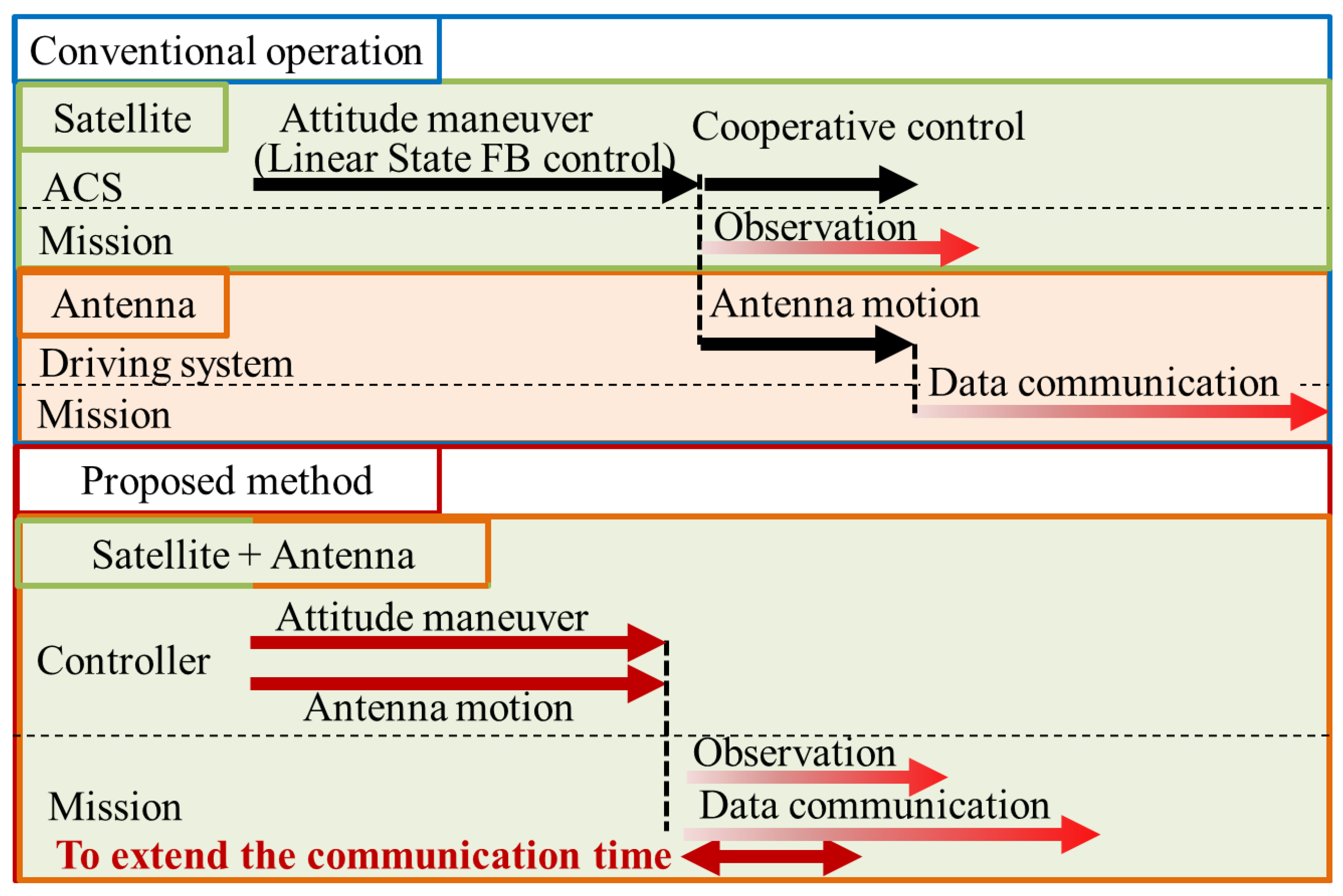
Owing to these reasons, it has become important to ensure that small Earth observation satellites use a data relay system in order to increase the time of data communication. In conventional operation, first, satellite maneuvers using linear state feedback controller. After that the data relay satellite communication (DRC) antenna is driven [8,9]. However, in this operation, there is loss of time between the completion of the attitude maneuver and the start of data communication. Therefore, we need to shorten the time between the start of attitude maneuver and the completion of the antenna motion. Accordingly, the purpose of this study is to increase the time of earth observation and data communication by carrying out satellite maneuver and antenna motion concurrently, as shown in Figure 2. Since a small satellite mounted with DRC antenna has a large mass ratio of the antenna, we cannot ignore the time variability of the moment of inertia of the whole system that is caused by antenna motion. In addition, a reaction torque generated by antenna motion is increased. In view of these points, we formulate the optimization problem that is subject to a state equation for the whole satellite system; the optimization problem is solved in order to design a satellite attitude controller by taking the influence of the antenna motion into consideration. On the other hand, a small satellite mounted with DRC antenna has the nonlinear equation of motion. Thus, it is difficult to design a linear state feedback controller. In recent years, the development of calculators is effectiveness in studying direct solvers that calculate approximate solutions, because it converts an optimal control problem active into a Nonlinear programming problem (NLP) [10]. Therefore, this study converts the optimization problem of minimum-time attitude maneuver and antenna motion into an NLP, and applies the sequential quadratic programming (SQP) method to obtain an optimal Feedforward (FF) control torque.
We assume an operation scenario as shown in Figure 3. In assumed scenario, first, we calculate the optimization problem of minimum-time attitude maneuver at a ground station. Second, we send the optimal FF control torque command to the satellite. Third, satellite carry out attitude maneuver and antenna motion. After that satellite can start missions. However, it is considered that model uncertainty of antenna [11,12] and unknown disturbance exists in real space. Thus, we have to design Feedback control to secure robustness in model uncertainty and unknown disturbance. In order to propose a nonlinear control method for carrying out Minimum-time satellite attitude maneuver and antenna motion which have robustness against model uncertainty and unknown disturbance, first, we calculate the reference attitude by the application of optimal control input torque to the ideal model. Next, we design servo controller in order to track time-variant as shown in Figure 4. Cloutier and Stansbery use the state-dependent Riccati equation (SDRE) control method to control position and attitude of two satellites in formulation flight. They design integral type servo controller to track a reference command [13,14,15]. Referring to [13,14,15], we design servo controller by using SDRE control method in order to track the time-variant reference attitude . In addition, SDRE control method has typical characteristic in that weighting matrix can be designed depending on the state. This means we can change the characteristic of controller depending on the state. Using this typical characteristic, we design state dependent weighting matrix in order to shorten the satellite attitude maneuver and antenna motion.
The paper is organized as follows. In Section 2, the small satellite mounted with DRC antenna kinematics and dynamics are defined and the error dynamics are formulated. In Section 3, we formulate the optimization problem of minimum-time attitude maneuver. And we convert the optimization problem into NLP and find a optimized FF control torque input and reference attitude. In Section 4, we describe the SDRE control method and we design SDLR of small satellite mounted with DRC antenna. In Section 5, we exhibit the design of the integral type servo controller expanding SDRE. In Section 6, numerical simulations were conducted to verify the effectiveness of the proposed method with the assumption that a small rigid satellite of 400 kg is mounted with a 50 kg communication antenna. The paper is then concluded with a conclusion section.
2. Modeling
2.1. Dynamics of the Satellite
The attitude dynamics of a rigid spacecraft can be shown as follow [16],
where is the angular momentum of whole satellite, is the angular velocity vector, and is the control torque input vector generated by the actuator. We are not interested in the disturbance torque.
2.2. Dynamics of the Satellite Mounted with DRC Antenna
A satellite model considered in this study is shown in Figure 5. We assume that DRC antenna has 2 gimbal axis and the Reaction wheel (RW) of the satellite are installed in each three axis of satellite and antenna joint motors can generate ideal torques. represents the satellite coordinate system where , , and are the unit vectors along the satellite coordinate axis. represents the antenna coordinate system, where , , and are unit vectors along the antenna coordinate axis. represents a rotation joint angle vector of the antenna relative to the satellite. represent the unit direction vectors of the joint angle , . represents the mass of the satellite, and represents the mass of the antenna. represents the inertia matrix of the satellite. represents the inertia matrix of the antenna. represents the distance between the center mass of the antenna and the axis . represents the distance between the center of mass of the satellite and the axis . represents the position vector of the center of mass of the satellite. represents the position vector of the center of mass of the antenna. represents the position vector of the center of mass of the whole satellite mounted with DRC antenna. represents the position vector of the joint rotation hinge. Each position vector is expressed by the following equation:
The inertia matrix for the antenna can be expressed in the satellite coordinate system as following equation
Considering that represents the unit matrix, and the inertia of the whole satellite around the center of mass of the whole satellite is represented by , then the inertia of the antenna around the center of mass of the whole satellite, can be expressed by following equation [17]:
can be expressed by the following equation:
The angular momentum of the whole satellite can be expressed by following equation:
2.3. Dynamics of Satellite Mounted with Reaction Wheel and DRC Antenna
In this study, we assume that Reaction wheel (RW) are installed in each three axis of satellite. The angular momentum of RW are shown as follow:
represents moment of inertia of one RW. represents wheel speed of RW in each axis. The angular momentum of whole satellite mounted with RW and DRC antenna can be rewritten by following equation:
2.4. Ideal Dynamics of the DRC Antenna
The DRC antenna uses stepping motors and harmonic drive gears as actuators. The dynamics of the DRC antenna can be expressed by following equation:
where and represents the rigidity, damping coefficient and reduction ratio of the harmonic drive gears. represents the rotation angle of the stepping motor which corresponds to the antenna joint angles . represents the torque acting at the antenna joints.
2.5. Model Uncertainty of DRC Antenna
It is mentioned that it is not easy to accurately estimate the mass and inertia characteristics of the antenna on the ground of the data relay satellite [11,12]. In this study, we assume that moment of inertia of DRC antenna has model uncertainty. The real inertia moment of DRC antenna can be expressed by the following equation:
2.6. Real Dynamics of DRC Antenna
We use the Equation (12) when we formulate optimization problem. However the real dynamics of the DRC antenna can be expressed by following equation:
where and can be expressed by the following equation:
3. Minimum-Time Attitude Maneuver of Small Satellite Mounted with DRC Antenna and RW
3.1. Converting the Optimization Problem into an NLP
The time-optimal rest-to-rest maneuvering control problem of a rigid spacecraft was studied. Lai et al. [18] presented a novel method to solve the time-optimal rest-to-rest maneuvering problem of a rigid spacecraft by transforming the problem into an NLP with the help of an iterative procedure. An NLP method does not utilize Pontryagin’s minimum principle which one needs to solve a set of difficult differential equations [19].
In this study, we considered only the control input to be discrete in order to convert the optimal problem into an NLP. The procedure used in converting the optimal problem into an NLP, is indicated as follows [20]:
- Step 1:
- We divide the time axis into elements of N, and defined a dimensionless time at each node as follows:
- Step 2:
- We fix the control input for each element as . The state vector can be calculated using Runge-Kutta 4th-order method, after substituting the control input into the state equation.
- Step 3:
- We define the time-independent decision variable X as follows:
We use X to convert the optimization problem into an NLP as follows:
where , represents an objective function which is a scalar value, and represents equality restriction conditions.
3.2. Formulation of the Problem of the Minimum-Time Attitude Maneuver of the Satellite Mounted with DRC Antenna and RW
In this study, we have assumed that antenna joint motor can create the output of an ideal torque. We defined control input vector and state vector as follows:
where represents quaternion vector of satellite attitude.
where represents the target satellite quaternion, and represents the target antenna angle.
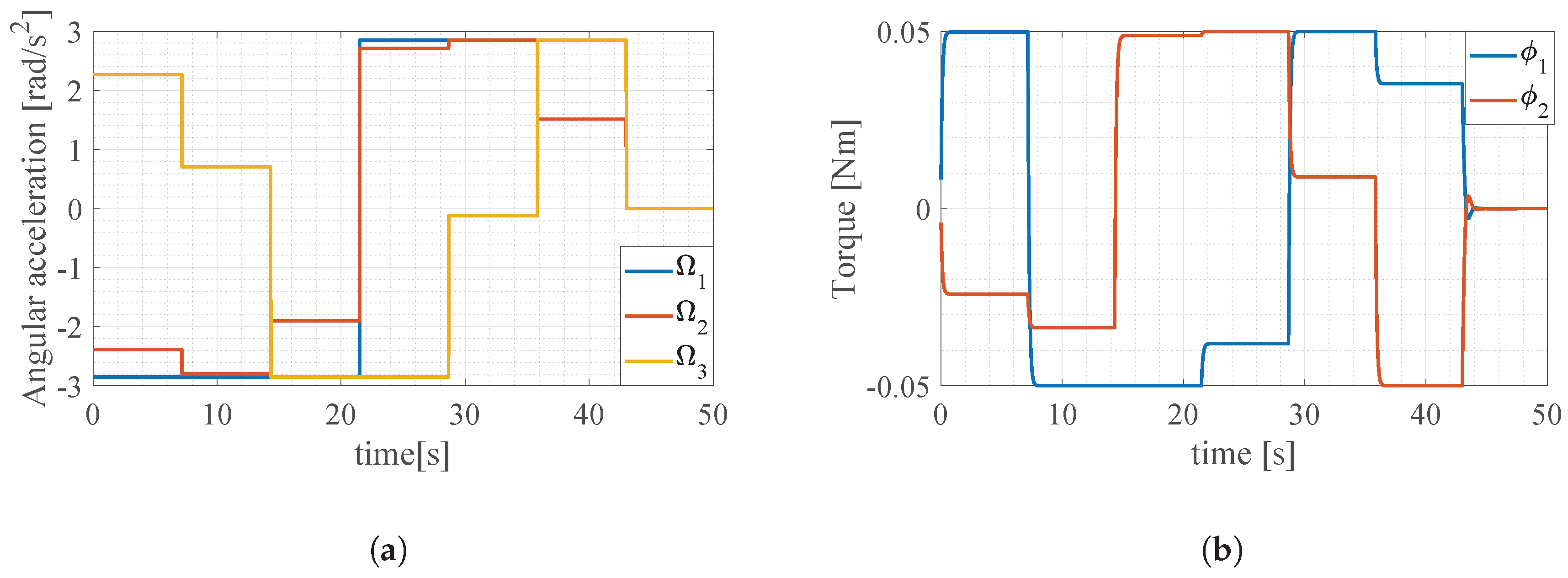
We used MATLAB® SQP algorithm [21] to solve the NLP. The decision variable X is repeatedly updated by iterative calculations until the end conditions are met. We realized the attitude maneuver and antenna motion, concurrently and rapidly, using the final X as a reference for feedforward control input.
Figure 6 shows the optimal control input that were calculated solving NLP. Figure 7 shows the time history of the satellite Euler angle and antenna angles with the application of optimization control input torques to the ideal model (Equation (12)) and real model (Equation (14)). In here, ideal model mean that we do not take modeling error into consideration and real model means that we take modeling error into consideration. We define the time history of the satellite Euler angle and antenna angles with the application of optimization control input torques to the ideal model as the reference trajectory. From Figure 7, we can confirm that the error of attitude exists in the case of the real model. Therefore, we should apply FB control to secure robustness in the model error.
4. The SDRE Method
As shown in the previous section, we must secure the robustness to model error by designing FB control. In this study, we use the SDRE method [13,14,15,22] to design an optimal servo control system.
4.1. SDRE Control Method
Consider the autonomous, infinite-horizon, non-linear regulator problem of minimizing the performance index J
with respect to the state and control , subject to the nonlinear differential constraints
where is the State-Dependent Weighting (SDW) matrix of the state vector and is the SDW matrix of the input vector and . The SDRE approach for obtaining a suboptimal, locally asymptotically stabilizing solution of problem Equations (22) and (23) is:
- Use direct parameterization to bring the nonlinear dynamics to the state dependent coefficient (SDC) formwhere a system is called a State-Dependent Linear Representation (SDLR). In the multivariable case, it is well known that if is a continuously differentiable function of , there is an infinite number of ways to factor into . In order to obtain a valid solution of the SDRE, the pair has to be pointwise stabilizable in the linear sense for all in the domain of interest.
- Solve the state-dependent Riccati equationto obtain .
- Construct the nonlinear feedback controller equation:
4.2. Design SDRE Controller of the Satellite Mounted with DRC Antenna and RW
We need to have satellite and antenna attitude track reference attitude which is obtained by adding the optimized FF control input to an ideal model. We define reference attitude as follows:
where represent reference of quaternion, reference of satellite angular velocity, reference of DRC antenna joint angle, reference of DRC antenna joint angular velocity and reference of RW wheel speed. In order to apply the SDRE controller, we need to rewrite the kinematics and dynamics of satellite mounted with antenna into an error dynamics representation because SDRE method is regulator controller. We define state vector , input vector and error dynamics as follow:
where is the unit matrix, and is a small negative error that needs to be chosen not to affect the system, and represents quaternion error vector. In order to written the nonlinear equations of satellite mounted with DRC antenna kinematics and dynamics in state space form, we substituted Equation (12) into Equation (8).
5. The SDRE Integral Type Servo Controller
5.1. SDRE Intergral Type Servo Controller Theory
In order to perform command following, the SDRE controller can be implemented as an integral servomechanism as demonstrated in [13]. The implementation of the integral servo can be accomplished by augmenting the state as
where is the vector integral state of . It is desired for the vector components of to track a reference command . The augmented system then becomes
The SDRE integral type servo controller is then given by
In order for the SDRE to have a solution, the pointwise detectability condition must be satisfied. This is accomplished by penalizing the integral states with the corresponding non-zero diagonal elements of .
5.2. SDRE Integral Type Servo Control Design
In order to track a time-variant reference attitude, we will augment the system with the integral state of quaternion, satellite velocity, antenna joint angle, and antenna joint angular velocity. Consequentially, we augment the state vector and system (Equation (28)) as follows:
- SDLR
- Objective function
- Riccati equation
- Optimal control input
5.3. Design of SDW Matrix
5.3.1. Simulations in Order to Understand the Influence of SDW Matrix
SDW matrix of state and SDW matrix of input can be expressed as follows:
where, is a SDW matrix for quaternion error , is a SDW for satellite angular velocity error , is a SDW matrix for antenna joint angle error , is a SDW matrix for antenna joint angular velocity error , is a SDW matrix for RW wheel speed error , is a SDW matrix for integral value of quaternion error , is a SDW matrix for integral value of satellite angular velocity error , is a SDW matrix for integral value of antenna joint angle error is a SDW matrix for integral value of antenna joint angular velocity error , is a SDW matrix for control input of RW angular acceleration , is a SDW matrix for control torque input of satellite actuator .
Firstly, in order to understand the influence of SDW matrix on characteristics of the SDRE servo control, we performed simulations with some fixed SDW matrix in two situation. In simulation I, we start the simulation with Initial RW wheel speed is zero. In simulation II, we start the simulation with assumption that RW has an initial wheel speed which is a disadvantageous condition for satellite attitude maneuver, and measuring error of RW wheel speed occurs. We show the simulation condition in Table 1. In Case 1, we have designed a large SDW matrix for the state error vector before the augment. In Case 2, we have designed a large SDW matrix for the integral of the state error vector. We show the parameters of SDW matrix in Table 2.
5.3.2. Results of Simulations
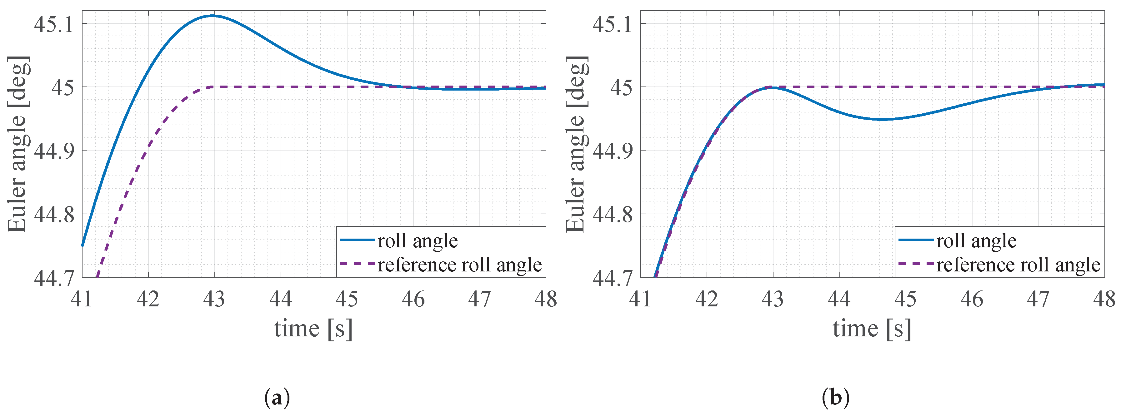
We show the results of simulations as shown in Figure 8. A solid line represents the Euler angle of the satellite and a dotted line represents the reference Euler angle of the satellite. From Figure 8a we can confirm that In Case 1, a steady state error occurs when the reference attitude is time-variant. On the other hand, Euler angle can be converged immediately as the reference attitude is fixed. From the results in Case 1, we can see that if the SDW matrix for a state error vector is large, the SDRE servo controller has the characteristics of a regulator. On the contrary, from Figure 8b we can find that in Case 2, Euler angle can track the time-variant reference attitude without steady state error. However, error occurs when the reference attitude is fixed. From the results in Case 2, we can see that if the SDW matrix for an integral of state error vector is large, the SDRE servo controller has the characteristics of a servo controller.
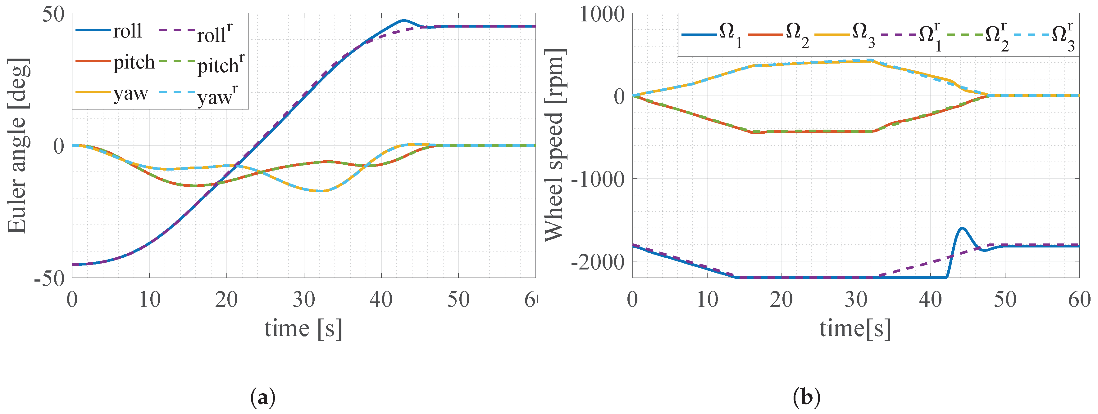
We show the results of simulation II as shown in Figure 9 and Table 3. From these results, we can confirm that when the measuring error of RW wheel speed occurs and RW wheel speed closes to , the SDRE servo controller the SDW matrix of which is Case 2 increase the settling time compared with the SDRE controller the SDW matrix of which is Case 1. This is because that overshoot occurs from 38 s to 48 s in order to reduce the integral value of state error which increased from 20 s to 38 s.
5.3.3. Design of SDW Matrix-Cooperative Control of RW and DRC Antenna
From results of simulation I, we find that it is necessary to switch the characteristics of SDRE servo controller from regulator to servo according to whether the reference trajectory is time-variant or not in order to shorten the time of settling time. More specifically, when the reference trajectory is time-variant, we are designing a large SDW matrix for an integral state error vector. When the reference trajectory is fixed, and the steady state error is small, we design a large SDW matrix for a state error vector as shown in Table 4. In order to switch the SDW matrix depending on reference trajectory, we augment the state vector and SDLR as follows:
To switch the SDW matrix, we define the sigmoid function as follows:
We show the sigmoid function in Figure 10. Next, we define the gain function as follows:
becomes 1 when the steady state error is small and reference trajectory is fixed. becomes 1 when the steady error is large or reference trajectory is time-variant.
On the other hand, from the results of simulation II, we can confirm that we should make the SDW matrix for state error vector when the steady error is large in order to reduce the overshoot that occurs between 38 s and 48 s. Therefore, we design the SDW matrix with the design guidelines as shown in Table 5. In Table 5 we make the SDW matrix for integral of state error vector large when the reference attitude is fixed and state error is large because we consider the case where unknown disturbance occurs when satellite is steady-state.
We carry out the simulation II using SDRE servo controller the SDW matrix of which is shown in Equations (45) and (46). And, we show the results in Table 6 and Figure 11. From Table 6, we can confirm that proposed method SDW matrix of which is shown in Equations (45) and (46) can reduce settling time compared with SDRE and SDRE servo the SDW matrix of which is fixed. This is because proposed method SDW matrix of which is shown in Equations (45) and (46) can reduce the overshoot compared with SDRE servo controller. However, the steady state error occurring from 20 s to 38 s when RW wheel speed reach the limit of it adversely affects attitude maneuver. Therefore, we design a cooperative control method to reduce the steady error caused by RW reaching performance limit. We design the cooperative control method so that the antenna motor generates torque for satellite attitude maneuver when RW reaches the limit of RW wheel speed.
From Equation (28), we can confirm that we can take the reaction torque generated by antenna motion into consideration in the SDLR. Thus we can mention that by making quite larger than the antenna motor gives priority to reducing the satellite angle error rather than reducing the antenna angle error. In addition, by making larger than antenna motor can generate the torque for satellite attitude maneuver instead of RW. Accordingly, in order to make the antenna motor generates torque for satellite attitude maneuver when RW reaches the limit of RW wheel speed we design the SDW matrix with the design guidelines as shown in Table 7 as follows:
Accordingly, we design the SDW matrix as shown in Table 8.
6. Simulations
In this report, we performed two simulations. Firstly, to verify the proposed method, we performed simulation I satellite model of which has model error and model uncertainty as shown in Equations (13) and (14), and compared with a LQR controller, SDRE controller, and SDRE controller SDW matrix of which is fixed. Secondly, to verify the SDRE servo cooperative controller the SDW matrix of which is proposed gain, we performed simulation II the RW has an initial wheel speed which is a disadvantageous condition for satellite attitude maneuver, and we assume that measuring error of RW wheel speed occurs.
We assumed that a small rigid satellite is 400 kg with reference to ASNARO-2 and DRC antenna is 50 kg with reference to DRC antenna of ALOS-2 which has been proven to perform communication between the DRT satellite. In addition we assume that the satellite was flying over Mongolia at 49° north of the latitude, and 90.75° east of the longitude. We calculated the initial and target antenna joint angles with the assumption that the DRC antenna points to KODAMA, which is also known as Japanese data relay test satellite [6]. We considered the motor delay characteristics of primary delay to be useful in modeling the actuator and the antenna joint motor. In this study, the primary delay time constant is 0.2. Table 9 shows each parameter.
6.1. Simulation I
6.1.1. Conditions of Simulation I
To verify the proposed method, we compared with LQR controller, SDRE controller, and SDRE servo controller the SDW of which is fixed. As the LQR controller, we define the target state as equilibrium, and the system becomes
6.1.2. Results of Simulation I
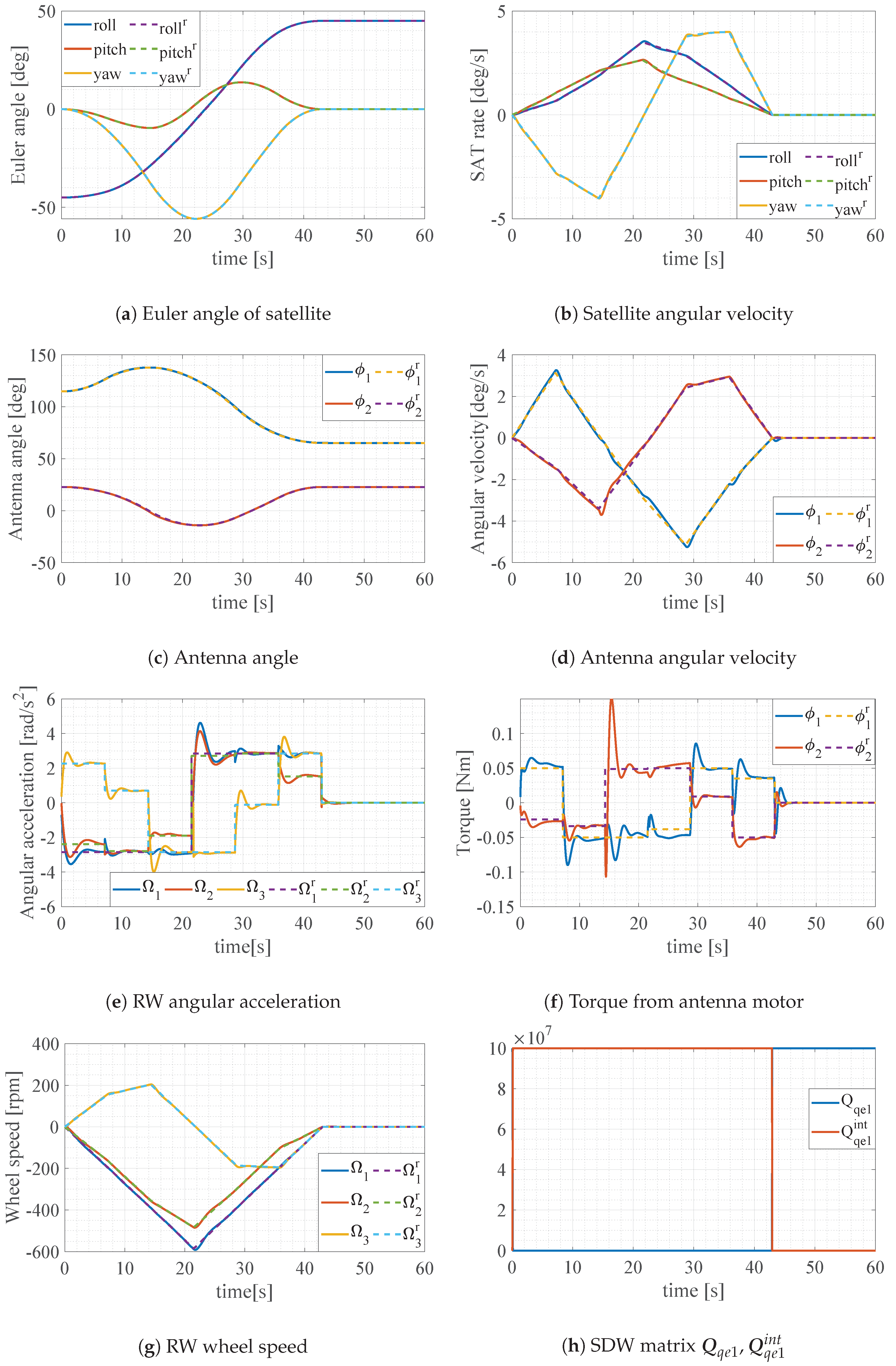
Figure 12 shows the time history of Euler angle of satellite, satellite angular velocity, antenna angle, antenna angular velocity, RW angular acceleration, Torque from antenna motor, RW wheel speed and SDW matrix () of proposed method. A solid line represents the time history of state and a dotted line represents the reference time history of state. From Figure 12a,c, we can confirm that proposed method can track a reference attitude. Figure 13a–d show the time history of the Euler angle around roll axis magnified near settling time. Figure 13e,f shows the RW angular acceleration of proposed method and SDRE servo. Figure 13g,h show the integral error of state vector of each controller.
Table 11 shows the settling time of the satellite and antenna of each method. From Table 11, we confirmed that the proposed method could track the reference attitude and reduced the settling time when compared with other controller. On the other hand, the SDRE servo controller the SDW of which is fixed increased settling time when compared with LQR controller and SDRE controller. Figure 13b shows the SDRE servo controller could track the reference attitude until 43 s, however the error of Euler angle around roll axis increased from 43 s to 47.8 s. This is because the torque from RW increased from 43 s to 47.8 s in order to reduce the error of integral state vector as shown in Figure 13h. In contrast, proposed controller could be track the reference attitude at all times as shown in Figure 13a. This is because we transformed the SDW matrix from a servo controller to a regulator when the reference trajectory is fixed, and steady error is shown in Figure 13h. Consequently, the responsiveness of the proposed controller is raised by prioritizing the reduction of the state vector error over the integral state vector error, as shown in Figure 13g.
6.2. Simulation II
6.2.1. Conditions of Simulation II
In simulation II, we assume that RW has initial wheel speed and measurement error as shown in Table 1. To verify the effectiveness of proposed method SDW matrix of which is shown in Table 8, we compared with LQR controller, SDRE controller, and SDRE servo controller the SDW of which is fixed as shown in Table 10.
6.2.2. Results of Simulation II
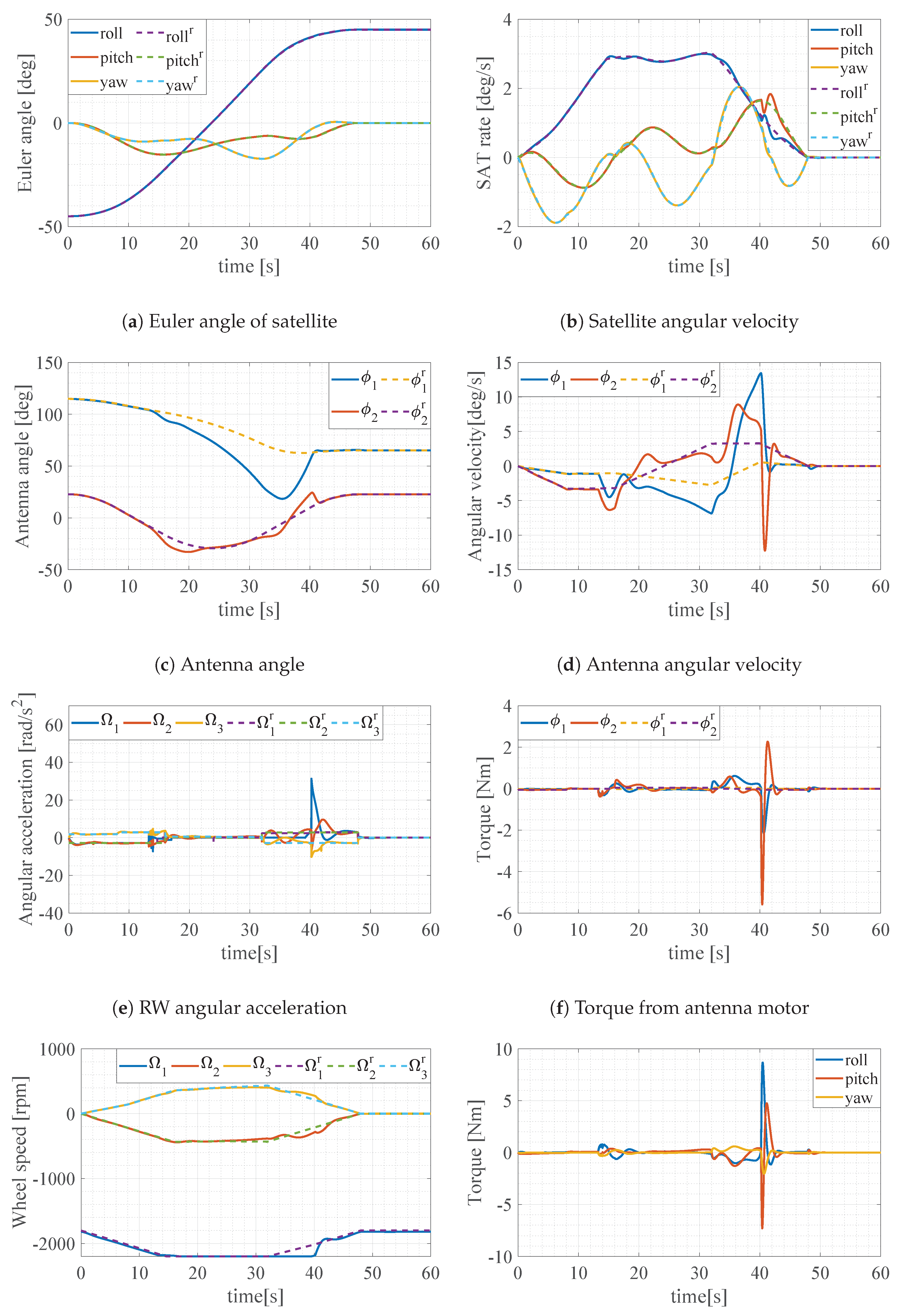
Figure 14 shows the time history of Euler angle of satellite, satellite angular velocity, antenna angle, antenna angular velocity, RW angular acceleration, Torque from antenna motor, reaction torque generated by antenna motion of proposed method. Figure 15 shows the time history of Euler angle of satellite in each control method and enlarged time history of reaction torque generated by antenna motion of proposed method.
Table 12 shows the settling time of the satellite and antenna of each method. From Table 12 and Figure 15, we can confirm that proposed method can reduce the settling time when compared with other controller.
From Figure 15e,g, we can confirm that in proposed method, the antenna motor generates torque for satellite attitude maneuver when RW reaches the limit of RW wheel speed so that the steady error can be reduced from 20 s to 30 s. As a results, the proposed method can track the reference attitude without steady error from 20 s to 30 s even though the steady error occurs when using other controllers.
7. Conclusions
The purpose of this study was to extend the time of earth observation and data communication by carrying out satellite maneuver and antenna motion concurrently. Due to the size of the satellite the effect of the antenna motion was significant and did affect the attitude of the system such as time variability of the moment of inertia of the whole system and reaction torque. Therefore, in order to take the effect of the antenna motion into consideration, we combined a satellite control system and an antenna drive system into one control system by governing equations and constructing the Minimum-time optimal control problem. To solve Minimum-time optimal control method. We converted the optimal control problem into a NLP by discretizing the control input (a series of pulses) to minimize the final time of the total maneuver that includes the antenna adjustment. On the other hand, it is considered that satellites have modeling error in real space and nonlinear equation. Therefore we designed robust controller by using SDRE control method. In proposed method, we calculated the reference attitude by the application of optimal control input torque to the ideal model. The reference attitude was time-variant so that we designed nonlinear servo controller by expanding SDRE control method. In addition, to reduce the settling time we designed proposed method which switch the SDW matrix. However, SDRE servo controller increased settling time when the measuring error of RW wheel speed occured and RW wheel speed closed to the limit value of it. Thus, we designed a cooperative control method to reduce the steady error caused by RW reaching performance limit. We design the cooperative control method so that the antenna motor generates torque for satellite attitude maneuver when RW reaches the limit of RW wheel speed.
We conducted two numerical simulations to verify the effectiveness of the proposed method. Using the results of the Simulation I, this study confirmed that the proposed method could reduce the settling time when compared with LQR, SDRE, SDRE servo controller by transforming the SDW matrix from a servo controller to a regulator, when the reference trajectory is fixed and the error is constant. In addition, from Simulation II, we confirmed that the proposed method could reduced the settling time comparatively with other controllers by antenna motor generating torque for satellite attitude maneuver when RW reaches the limit of RW wheel speed.
Although this paper assumes that a small rigid satellite of 400 kg was mounted with a 50 kg DRC antenna, it is considered that the antenna mass ratio may be different from this paper for example in the case of LEO to LEO link. Therefore it is necessary to verify how the effectiveness of the proposed method varies depending on the antenna mass ratio by performing numerical simulations with various antenna mass ratios in the future work.
Author Contributions
K.M. and M.T. conceived and designed the proposed method and verification simulations; K.M. performed the numerical simulations; K.M. wrote the paper.
Acknowledgments
This work was supported by education and research fund from Keio University.
Conflicts of Interest
The authors declare no conflict of interest.
Nomenclature
| Satellite coordinate system | |
| Antenna coordinate system | |
| Relative rotation joint angle vector of the antenna with respect to the satellite | |
| Inertia of the whole satellite around the center of mass of the whole satellite | |
| Inertia matrix of the antenna around the center of mass of the whole satellite | |
| N | Elements of dividing the control input |
| Settling time of satellite and antenna | |
| X | Decision variable of Nonlinear programming problem |
Abbreviations
The following abbreviations are used in this manuscript:
| ASNARO | Advanced satellite with New system architecture for observation |
| NEC | Nippon Electric Company |
| LEO | Low Earth orbit |
| DRTS | Data relay test satellites |
| GEO | Geostationary orbit |
| ACS | Attitude control system |
| DRC | Data relay communication |
| NLP | Nonlinear programming problem |
| SQP | Sequential quadratic programming |
| RW | Reaction wheel |
References
- Strategic Headquarters for Space Policy Government of Japan. Basic Plan for Space Policy Strategic Headquarters for Space Policy; Space Policy Government of Japan: Tokyo, Japan, 2009.
- Kasai, R.; Oniyama, A.; Fukunaga, T. User-oriented Operation of ASNARO. In Proceedings of the 14th International Conference on Space Operations (SpaceOps 2016), Daejeon, Korea, 16–20 May 2016; pp. 2016–2581. [Google Scholar]
- Fujimura, T.; Kimura, T.; Ogawa, T. Small optical sensor satellite “asnaro”and series of small earth observation satellites. In Proceedings of the 2012 IEEE International Geoscience and Remote Sensing Symposium, Munich, Germany, 22–27 July 2012; pp. 229–232. [Google Scholar]
- Wu, Y.H.; Hu, Y.B.; Hua, B.; Chen, Z.M.; Ge, L.L. A time suboptimal method for real-time spacecraft attitude agile maneuvering with angular velocity constraint. Proc. Inst. Mech. Eng. Part G J. Aerosp. Eng. 2017, 233. [Google Scholar] [CrossRef]
- Yokota, Y.; Okada, Y.; Iribe, K.; Tsuji, M.; Ando, A.; Kunii, Y. Newly developed X-band SAR system onboard Japanese small satellite “ASNARO-2”. In Proceedings of the IEEE Conference 2013 Asia-Pacific Conference on Synthetic Aperture Radar (APSAR), Tsukuba, Japan, 23–27 September 2013; pp. 81–83. [Google Scholar]
- Fujiwara, Y.; Sudo, Y.; Nagano, H.; Kanamori, Y. Japan’s First Data Relay Test Satellite (DRTS). In Proceedings of the 54th International Astronautical Congress of the International Astronautical Federation, the International Academy of Astronautics, and the International Institute of Space Law, Bremen, Germany, 29 September–3 October 2003. [Google Scholar]
- Eilertsen, B.; Hyvonen, P. Ground station networks vs. GEO relay satellite systems for polar orbiting satellites. In Proceedings of the 12th International Conference on Space Operations, Stockholm, Sweden, 11–15 June 2012. [Google Scholar]
- Iwata, T. Attitude and Pointing Dynamics of the Advanced Land Observing Satellite (ALOS): Flight Results and Characterization. J. Space Technol. Sci. 2007, 23, 1_20–1_29. [Google Scholar]
- Ueno, T.; Ukawa, S.; Sugita, M.; Suzuki, T.; Shima, T.; Arikawa, Y. ALOS-2 On-Orbit evaluation results of the attitude/antenna cooperative control method and an antenna alignment error estimation method. In Proceedings of the 57th Japan Joint Automatic Control Conference, Lisbon, Portugal, 10–12 November 2014; pp. 1882–1887. [Google Scholar]
- Hargraves, C.R.; Paris, S.W. Direct Trajectory Optimization Using Nonlinear Programming and Collocation. J. Guid. Control Dyn. 1987, 10, 338–342. [Google Scholar] [CrossRef]
- Shimada, M.; Nakashima, A.; Yamada, K.; Miyazaki, K.; Matsue, T. Cooperation Control Experiment of Communications and Broadcasting Engineering Test Satellite (COMETS). Trans. JSME 2000, 66, 232–239. [Google Scholar] [CrossRef]
- Yamada, K.; Yonechi, H.; Wakao, M.; Fujiwara, Y.; Kosugi, S. Function Test of Adaptive Attitude Control System of the Data Relay Test Satellite. Trans. JSME 2004, 70, 97–104. [Google Scholar] [CrossRef] [Green Version]
- Cloutier, J.R.; Stansbery, D.T. Control of a Continuously Stirred Tank Reactor Using an Asymmetric Solution of the State-Dependent Riccati Equation. In Proceedings of the IEEE International Conference on Control Applications (Cat. No. 99CH36328), Kohala Coast, HI, USA, 22–27 August 1999; Volume 2, pp. 893–898. [Google Scholar]
- Stansbery, D.; Cloutier, J. Nonlinear control of satellite formation flight. In Proceedings of the AIAA Guidance, Navigation, and Control Conference and Exhibit, Denver, CO, USA, 14–17 August 2000. No. 4436. [Google Scholar]
- Stansbery, D.; Cloutier, J. Position and attitude control of a spacecraft using the state-dependent Riccati equation technique. In Proceedings of the 2000 American Control Conference, Chicago, IL, USA, 28–30 June 2000; Volume 3, pp. 1867–1871. [Google Scholar]
- Wie, B.; Lu, J. Feedback control logic for spacecraft eigenaxis rotations under slew rate and control constraints. J. Guid. Control Dyn. 1995, 1, 1372–1379. [Google Scholar] [CrossRef]
- Kane, T.R.; Levinson, D.A. Dynamics, Theory and Applications; McGraw-Hill: New York, NY, USA, 1985. [Google Scholar]
- Lai, L.C.; Yang, C.C.; Wu, C.J. Time-optimal maneuvering control of a rigid spacecraft. Acta Astron. 2007, 60, 791–800. [Google Scholar] [CrossRef]
- Chung, T.S.; Wu, C.J. A computationally efficient numerical algorithm for the minimum-time control problem of continuous systems. Automatica 1992, 28, 841–847. [Google Scholar] [CrossRef]
- Mori, K.; Takahashi, M. Minimum-time Attitude Maneuver of Small Satellite Mounted with Communication Antenna. In Proceedings of the 2018 Space Flight Mechanics Meeting, Kissimmee, FL, USA, 8–12 January 2018. No. 0472. [Google Scholar]
- Gill, P.E.; Murray, W.; Wright, M.H. Numerical Linear Algebra and Optimization; Addison-Wesley: Redwood City, CA, USA, 1991. [Google Scholar]
- Ozawa, R.; Takahashi, M. Agile Attitude Maneuver via SDRE Controller using SGCMG Integrated Satellite Model. In Proceedings of the 2018 AIAA Guidance, Navigation, and Control Conference, Kissimmee, FL, USA, 8–12 January 2018. No. 1579. [Google Scholar]
Figure 1.
Image of Data Relay System.

Figure 2.
Concept of Proposed Method.

Figure 3.
Image of satellite operation.

Figure 4.
Control structure of proposed method

Figure 5.
Model of satellite mounted with a directional routing table (DRC) antenna.

Figure 6.
Reference control input calculated by SQP. (a) Reference control input of RW; (b) Reference control input of antenna motor.
Figure 6.
Reference control input calculated by SQP. (a) Reference control input of RW; (b) Reference control input of antenna motor.

Figure 7.
Time history of input the optimal FF control to the real model and ideal model. (a) Time history of satellite Euler angle; (b) Time history of antenna joint angle.
Figure 7.
Time history of input the optimal FF control to the real model and ideal model. (a) Time history of satellite Euler angle; (b) Time history of antenna joint angle.

Figure 8.
Results of simulations I. (a) Euler angle of satellite (Case 1); (b) Euler angle of satellite (Case 2).
Figure 8.
Results of simulations I. (a) Euler angle of satellite (Case 1); (b) Euler angle of satellite (Case 2).

Figure 9.
Results of simulation II. (a) Euler angle of satellite (Case 1); (b) Satellite angular velocity (Case 1); (c) Euler angle of satellite (Case 2); (d) Satellite angular velocity (Case 2).
Figure 9.
Results of simulation II. (a) Euler angle of satellite (Case 1); (b) Satellite angular velocity (Case 1); (c) Euler angle of satellite (Case 2); (d) Satellite angular velocity (Case 2).

Figure 10.
Sigmoid function of proposed method .

Figure 11.
Results of simulation SDW matrix of which is shown in Equations (45) and (46). (a) Euler angle of satellite; (b) Satellite angular velocity.
Figure 11.
Results of simulation SDW matrix of which is shown in Equations (45) and (46). (a) Euler angle of satellite; (b) Satellite angular velocity.

Figure 12.
Simulation I results of Proposed method.

Figure 13.
Simulation results of Simulation I.

Figure 14.
Simulation II results of Proposed method.

Figure 15.
Results of Simulation II.


Table 1.
Initial RW wheel speed.
| Ideal Initial RW Wheel Speed | Real Initial RW Wheel Speed | |
|---|---|---|
| Simulation I | [rpm] | [rpm] |
| Simulation II | [rpm] | [rpm] |
Table 2.
SDW matrix parameters of simulation.
| Symbols | Case 1 | Case 2 | Symbols | Case 1 | Case 2 |
|---|---|---|---|---|---|
| (0, , , ) | (0, 0, 0, 0) | (0, 0, 0, 0) | (0, , , ) | ||
| (, , ) | (0, 0, 0) | (0, 0, 0) | (, , ) | ||
| (, ) | (0, 0) | (0, 0) | (, ) | ||
| (, ) | (0, 0) | (0, 0) | (, ) | ||
| (0, 0, 0) | (0, 0, 0) | ||||
| (10, 10, 10) | (10, 10, 10) | (, ) | (, ) |
Table 3.
Settling time of simulation II.
| SDRE | SDRE Servo | |
|---|---|---|
| settling time | 52.82 s | 57.04 s |
Table 4.
Design guidelines.
| reference trajectory is time-variant | is large |
| reference trajectory is fixed | is large |
Table 5.
Design guidelines.
| reference trajectory is time-variant | steady state error is large | is large |
| steady state error is small | is large | |
| reference trajectory is fixed | steady state error is large | is large |
| steady state error is small | is large |
Table 6.
Settling time of simulation SDW matrix of which is shown in Equation (45) and Equation (46).
Table 6.
Settling time of simulation SDW matrix of which is shown in Equation (45) and Equation (46).
| SDW Matrix as Shown in Equations (45) and (46) | SDRE | SDRE Servo | |
|---|---|---|---|
| settling time | 51.86 s | 52.82 s | 57.04 s |
Table 7.
Design guidelines of proposed method.
| rpm | rpm | |
|---|---|---|
Table 8.
SDW matrix parameters of proposed SDRE integral type servo method.
| Symbols | Proposed | Symbols | Proposed | Symbols | Proposed | Symbols | Proposed |
|---|---|---|---|---|---|---|---|
| Equation (45) | (, , ) | Equation (47) | (, ) | ||||
| Equation (46) | (, , ) | (0, 0) | (0, 0) | ||||
| (0, 0, 0) | Equation (48) | (, , ) |
Table 9.
Simulation parameters.
| Parameters | Symbols | Values | Unit |
|---|---|---|---|
| Inertia of satellite main body | diag(166.7, 166.7, 66.67) | ||
| Inertia of antenna (coordinates of the antenna) | diag(2.96, 3.71, 2.96) | ||
| Real inertia of antenna (coordinates of the antenna) | diag(3.26, 4.08, 3.26) | ||
| Inertia of Reaction wheel | diag(0.2383, 0.2383, 0.2383) | ||
| Initial attitude angle of satellite | deg | ||
| Maximum value of RW wheel speed | 2200 | rpm | |
| Target attitude angle of satellite | deg | ||
| Initial joint angle of antenna | deg | ||
| Target joint angle of antenna | deg | ||
| Elements of dividing the control input | N | 6 | pcs |
| Control cycle | 0.02 | s | |
| Settling conditions of satellite | deg | ||
| Settling conditions of antenna | deg |
Table 10.
SDW matrix parameters of comparative method.
| B | LQR & SDRE | SDRE Integral Type Servo Servo (Fixed) |
|---|---|---|
| (0, , , ) | (0, , , ) | |
| (, , ) | (, , ) | |
| (, ) | (, ) | |
| (, ) | (, ) | |
| - | (0, , , ) | |
| - | (, , ) | |
| - | (, ) | |
| - | (, ) | |
| (10, 10, 10) | (10, 10, 10) | |
| (, ) | (, ) |
Table 11.
Results of Simulation I.
| Method | Settling Time |
|---|---|
| LQR | 47.42 s |
| SDRE | 47.56 s |
| SDRE servo | 47.58 s |
| Proposed method | 44.70 s |
Table 12.
Results of Simulation II.
| Method | Settling Time |
|---|---|
| LQR | 52.78 s |
| SDRE | 52.82 s |
| SDRE servo | 53.98 s |
| Proposed method | 50.70 s |
© 2019 by the authors. Licensee MDPI, Basel, Switzerland. This article is an open access article distributed under the terms and conditions of the Creative Commons Attribution (CC BY) license (http://creativecommons.org/licenses/by/4.0/).
Share and Cite
MDPI and ACS Style
Mori, K.; Takahashi, M. Minimum-Time Attitude Maneuver and Robust Attitude Control of Small Satellite Mounted with Data Relay Communication Antenna. Appl. Sci. 2019, 9, 1001. https://doi.org/10.3390/app9051001
AMA Style
Mori K, Takahashi M. Minimum-Time Attitude Maneuver and Robust Attitude Control of Small Satellite Mounted with Data Relay Communication Antenna. Applied Sciences. 2019; 9(5):1001. https://doi.org/10.3390/app9051001
Chicago/Turabian StyleMori, Kota, and Masaki Takahashi. 2019. "Minimum-Time Attitude Maneuver and Robust Attitude Control of Small Satellite Mounted with Data Relay Communication Antenna" Applied Sciences 9, no. 5: 1001. https://doi.org/10.3390/app9051001
Note that from the first issue of 2016, this journal uses article numbers instead of page numbers. See further details here.