
Investigation of the LME Susceptibility of Dual Phase Steel with Different Zinc Coatings


1
Fraunhofer Insitute for Production Systems and Design Technology IPK, Pascalstraße. 8–9, 10587 Berlin, Germany
2
Institut für Werkzeugmaschinen und Fabrikbetrieb IWF, Technische Universität Berlin, FG Fügetechnik Straße des 17. Juni 135, 10623 Berlin, Germany
3
Bundesanstalt für Materialforschung und-Prüfung (BAM), Unter den Eichen 87, 12205 Berlin, Germany
*
Author to whom correspondence should be addressed.
Metals 2023, 13(5), 890; https://doi.org/10.3390/met13050890
Submission received: 21 March 2023
/
Revised: 5 April 2023
/
Accepted: 1 May 2023
/
Published: 5 May 2023
(This article belongs to the Section Welding and Joining)
Abstract
:The application of anti-corrosion coated, high-strength steels in the automotive industry has increased in recent years. In combination with various zinc-based surface coatings, liquid metal embrittlement cracking can be observed in some of these materials. A high-quality, crack-free spot-welded joint is essential to realize the lightweight potential of the materials. In this work, the LME susceptibility of different coatings, which will be determined by the crack length and the occurrence rate, will be investigated using a welding under external load setup. The uncoated specimens did not show any LME. EG, GI and GA showed significantly less LME than ZM coatings. The latter coatings showed much larger crack lengths than the EG, GI and GA coatings. Furthermore, two mechanisms regarding the LME occurrence rate were observed: the occurrence of LME in zinc–magnesium coatings was theorized to be driven by the material properties of the coatings, whereas the occurrence of LME at EG, GI and GA samples was forced mainly by the application of the external tensile load. In the experimental setup of this work, the materials were exposed to unusually high mechanical loads (up to 80% of their yield strength) to evoke LME cracks.
1. Introduction
The implementation of lightweight construction concepts is essential for the automotive industry to meet their emission goals and to increase driving safety. Hence, advanced high-strength steels (AHSS) are widely used in car body manufacturing because they combine superior elongation and a high tensile strength. Hence, the application of AHSS allows for a reduction in car body mass by downsizing the sheet thickness [1]. For anti-corrosion purposes, those steels are protected with zinc-based coatings. Resistance spot welding (RSW) is commonly used to join such steel grades [2]. However, the application of RSW under certain process conditions can lead to the formation of cracks caused by liquid metal embrittlement (LME) [3] at different locations within a spot weld joint [4]. LME cracks at the weld shoulder can be considered as a sign of insufficient weld quality [5]. Further, if the LME cracks are sufficiently long and oriented across the load path, they can have a negative impact on the weld tensile shear and impact strength [6].
In general, LME cracking is governed by tensile stresses [7], a susceptible microstructure and grain boundary penetration by liquid metal alloying elements in steels. The welding process parameters can have an impact on the occurrence of liquid zinc and the tensile stresses. Bhattacharya [8] assumes that the formation of LME is caused by the stress-assisted penetration of the liquified zinc coating along the steel’s grain boundaries, which successively leads to a subsequent reduction in its structural cohesion. Frei et al. [9] investigated the influence of industry-relevant parameters on the occurrence of LME. They established a 3D electro-thermomechanical model to investigate the underlying stresses and strains responsible for the occurrence of LME [7]. The authors succeeded in predicting the time range where liquid zinc and high plastic deformation occur, both of which are essential for the formation of LME. Bhattacharya et al. [10] performed hot tensile tests to determine the critical temperature conditions for LME. In the range between 700 °C and 900 °C, higher temperatures forced more LME. DiGiovanni et al. [11] investigated the influence of different welding electrode geometries on the severity of the LME cracks. The authors found out that a radius tip electrode provides less cracking than a truncated cone shape. Murugan et al. [12] define in their work critical design parameters of the electrode to suppress LME during RSW.
Kim et al. [13] analyzed the coating microstructure and thermomechanical characteristics at various weld regions. The authors identified an α-Fe (Zn) layer that inhibits the liquid zinc from contacting the steel substrate. A similar observation regarding α-Fe (Zn, Al) layers was made by Ghatei Kalashami et al. [14]. Long-duration, high-magnitude tensile stress can fragment the α-Fe (Zn) layer and enable LME cracking. Hence, the Zn-coating process has a significant influence on the LME susceptibility [15]. Wang et al. [16] conducted hot tensile tests on zinc-coated steels and uncoated specimens. They found out that the zinc-coated steels had a reduced plastic deformation, which reinforced the occurrence of LME.
Böhne et al. [17] showed, both experimentally and numerically, that larger electrode tips reduce the indentation depth and the resulting plastic deformation at the indentation area. Hence, the authors were able to reduce the occurrence of LME through the application of different electrode caps. Böhne et al. [18] also investigated the effect of the hold time on the occurrence of LME. The authors showed that an elongated hold time can avoid LME cracks, which are formed after the weld current switch-off. Ashiri et al. [19] developed a simulation-based method to control the heating during RSW to obtain LME-free welds. Choi et al. [20] showed that an elevated electrode force can reduce the LME crack size or avoid LME cracks on the surface. DiGiovanni et al. [21] concluded that a welding current ramp down reduced the LME severity by 60% compared to a standard constant current. Wintjes et al. [22] experimented with two different types of pulsing methods. The authors found that a pre-pulse before the welding current to remove the zinc coating and pulsing during the welding current to manage the heat generation could reduce the LME crack severity. The authors stated that multiple pulse welding schedules may be successfully used to reduce LME cracking. Song et al. [23] observed a significant influence of expulsion during RSW on the formation of LME cracks.
Due to the impact that these cracks have on automotive weld quality, finding LME-resistant welding procedures and low LME susceptible steel grades is a high priority for steel producers and automotive manufacturers. LME can be enforced by an experimental procedure, during which tensile stresses are applied to a sample, shaped similarly to a typical flat tensile specimen during welding [24]. DiGiovanni and Biro [25] compared different LME test setups and proposed standardizing LME tests. Most research has focused on the investigation of the underlying effects of LME and avoidance strategies. Many of the latter are not applicable in an industrial environment due to the specific boundary conditions of mass production. There are no standardized investigations of different coatings. In this work, an LME test setup with comparable boundary conditions is implemented and different coatings are studied with regard to their LME susceptibility.
2. Materials and Methods
In this work, a total of six dual phase (DP) steels of the tensile strength class 800 MPa (hereinafter called DP800) with different coatings were studied. The coatings were uncoated (U), electrogalvanized (EG), galvannealed (GA), galvanized (GI) and zinc–magnesium coatings (ZM1 and ZM2) from two different suppliers. The materials are listed in Table 1. The sheet thicknesses ranged from 1.0 mm to 1.8 mm and the yield strength ranged from 491 MPa to 538 MPa. All materials were sourced from project partners from industry and anonymized. The chemical analysis of the coating was limited to disclosure of the main components as shown in Table 2 as a requirement for pre-competitiveness.
The welding experiments were performed with a servo-electric C-type spot welding gun, using a 1000 Hz medium frequency DC power source. Electrode caps of type F1-16-20-5.5, as specified in ISO 5821, were used. To enhance the comparability, all welding experiments were performed with a fixed electrode force of 4.5 kN and a squeeze time of 300 ms. The welding current range (WCR) was determined in accordance with SEP 1220. In the standard, a welding time of 380 ms and a holding time of 300 ms was proposed for coated steels. The minimum welding current was determined as the current where at least a minimum spot diameter of four times the square root of the sheet thickness was reached. The maximum welding current lay 100 A below the expulsion limit.
To evaluate the LME susceptibility of the different materials, welding under external load setup was used. A specimen was clamped into the setup and a tensile load was applied hydraulically. The tensile force was adjusted initially. During the application of the tensile load, the specimen was spot welded with a joining partner. Then, the zinc was removed from the spot weld using hydrochloric acid and microscopic images were taken to evaluate the occurrence of LME. The welding under external load test setup was carried out with a tensile specimen geometry, which was depicted in Figure 1a. To avoid any thermal effects, the specimens were produced by waterjet cutting. Figure 1c,d show an exemplary specimen after removing the zinc from the spot weld. The LME cracks are marked yellow in Figure 1d, and they are typically all located on the electrode indentation shoulder.
Ten samples were tested for every tensile load level, due to the scattering of the LME occurrence. To ensure uniform electrode wear across all tensile load levels, a randomized test sequence of the tensile load levels was chosen. The welding trials were performed with one set of electrode caps per material. To avoid any changes in the electrode caps, only experiments without expulsion were considered. If any expulsion occurred, then the electrode caps were changed. For all experiments, only electrode caps with a welding history of 50 welds at 3 kA for each material were used. The tensile load was calculated as follows:
where Ftensile is the applied tensile force, Rp0.2 is the yield strength, A denotes the cross-section area and P represents the tensile load level. The maximum tensile force during the experiments was 9 kN, which represents a tensile load level of 80%.
Ftensile = Rp0.2 ∙ A ∙ P,
As the heat input has an essential influence on the occurrence of LME [26], it needs to be closely monitored and can be determined directly by the RSW process parameters. To enhance the comparability of the experimental results, it was necessary to align the heat input for every test series. Therefore, all the welding experiments were conducted with the same electrode force (4.5 kN), the same welding time (380 ms) and the same holding time (300 ms). Due to the different shape of the WCR of the materials, the welding current was adjusted so that for every material the nugget size was 5 times the square root of the sheet thickness.
From the welding under external load test setup, two result values could be obtained: the total LME crack length and the LME occurrence rate.
3. Results and Discussion
Figure 2 shows the different WCRs of the tested materials. All WCRs were larger than 1 kA, which is usually an important quality specification to ensure a stable process in industrial production. Due to the different locations of the WCRs, it was difficult to set a welding current for all materials. Hence, a heat input alignment was necessary.
The heat input is related to the spot diameter in relation to the sheet thickness. Hence, it was assumed that all spot diameters with a nugget size five times the square root of the sheet thickness have the same heat input. Table 3 shows the tested materials and their normalized welding currents, and a diameter over square root of the sheet thickness factor between 5.0 and 5.3 could be reached.
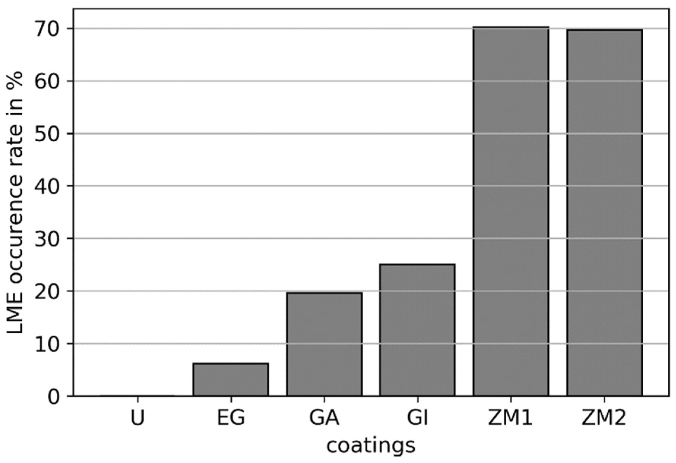
In Figure 3, the LME occurrence rate for the different coatings is depicted in a bar chart. As expected, the uncoated specimens did not show any cracks, because the occurrence of LME is directly linked to the availability of liquid zinc. It can be seen that less than 10% of the EG samples showed at least one LME crack. Every fifth GA sample showed an LME crack, and every fourth GI specimen was affected with LME. Most LME occurred in the zinc–magnesium samples, where LME was observed in a total of two thirds of the samples LME. From the LME occurrence rate, a certain LME susceptibility of the different coatings could be derived: zinc–magnesium coatings in combination with AHSS seemed to be more vulnerable to LME cracking than the other coatings, such as EG, GA and GI. Bhattacharya [8] came up with a similar ranking of the LME susceptibility of the coatings studied here from various literature sources.
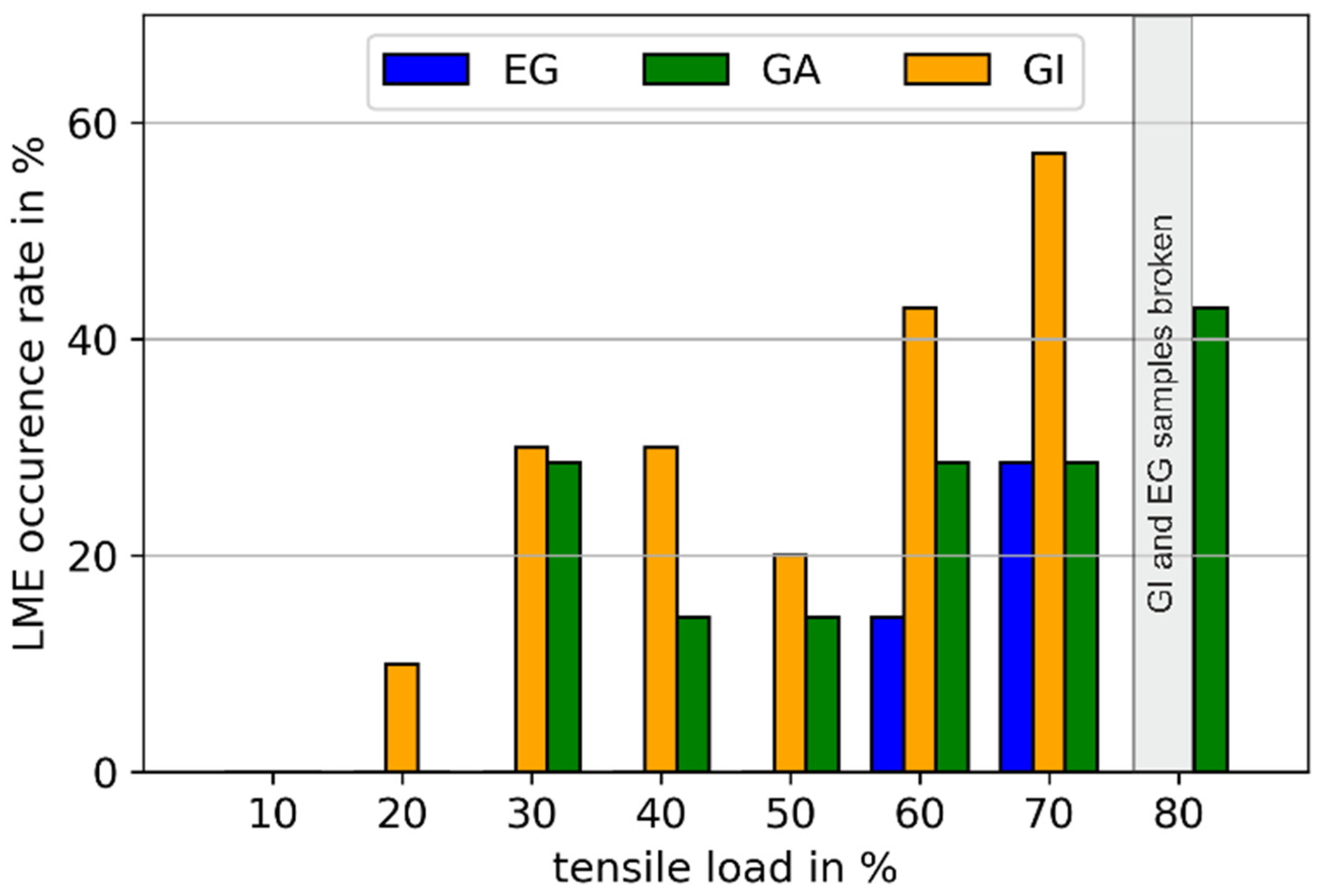
After calculating the LME occurrence rate for every material, the distribution of all LME occurrences over the tensile load levels can be studied. Figure 4 shows the LME occurrence rates of EG, GA and GI over the applied tensile load levels. The LME occurrence rates rose continuously with higher tensile load levels. Hence, it can be stated that the LME occurrence is significantly driven by the applied tensile load. This can be related to the findings of Böhne et al. [17] and Frei et al. [7]. The authors emphasized that especially high plastic deformation, which is connected to the high tensile loads, is a major driver of LME cracking. In particular, EG samples showed only LME at tensile loads higher than 60%, which is similar to the observations of Frei et al. [9]. The authors used a similar welding under external load setup. It can be seen that the opportunity for the liquid zinc to penetrate the steel is different for each tensile load level. For instance, no LME cracks occurred at a tensile load of 10% in all three coatings. The first LME cracks occurred in GI at a tensile load of 20%. From 30% to 70%, the number of GI samples with LME increased continuously. At 80% tensile load, all GI specimens broke during the resistance spot welding due to the weakening of the mechanical structure of the substrate; therefore, the LME cracks were not counted due to the lack of comparability. The first LME cracks in the GA specimens occurred at a tensile load of 30% and increased, similar to GI, continuously until a tensile load of 70%. From the EG specimens, it can be determined that the liquid zinc of the coating during the range from 10% to 50% was insufficient to produce any LME cracks. The reason could be that the mechanical structure was still able to withstand the infiltration of liquid zinc. From these results, it can be assumed that for the occurrence of LME a certain level of tensile load and a certain amount of liquid zinc are necessary. More available liquid zinc, as in the case of GA and GI, causes LME cracks to occur at lower tensile loads.
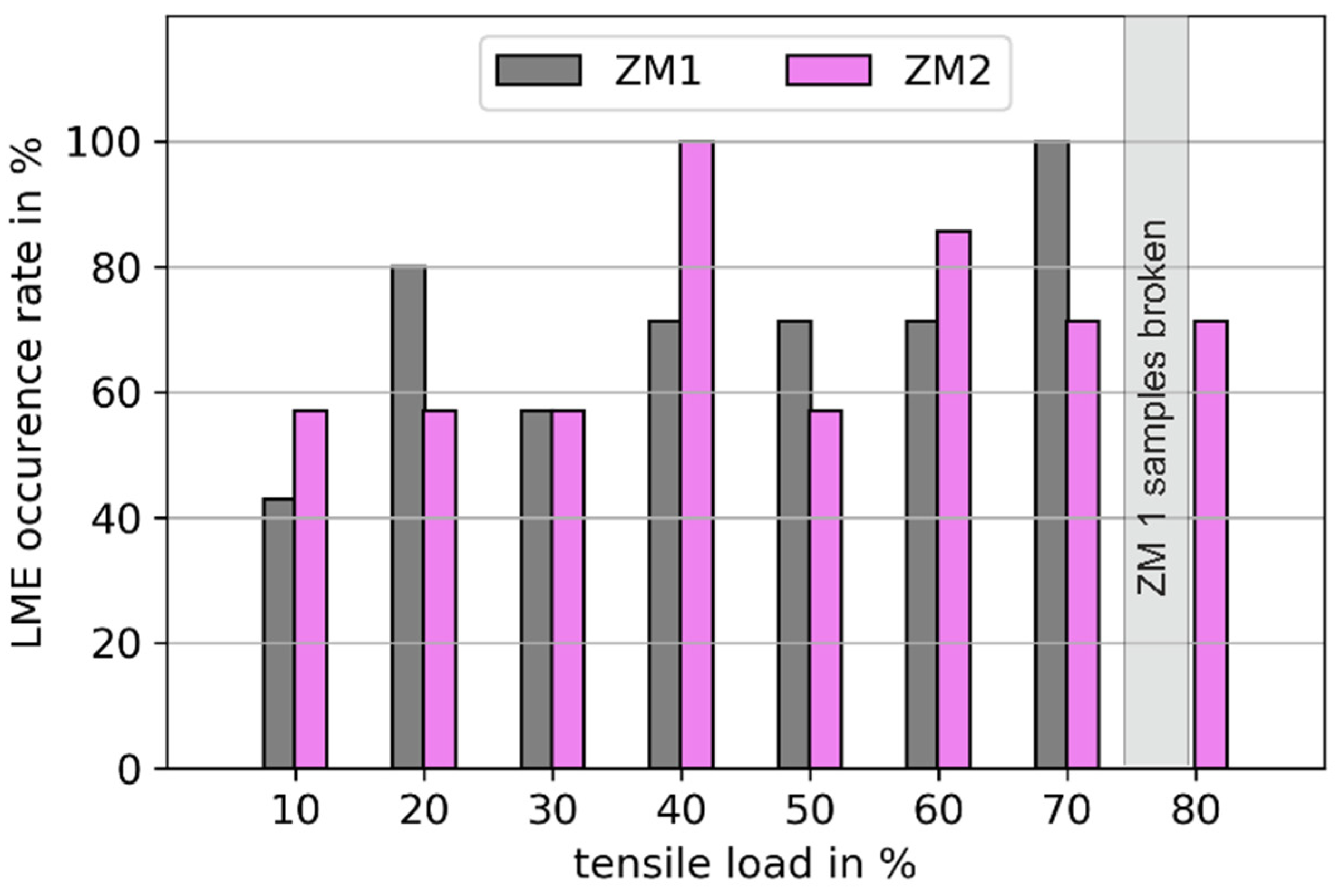
Figure 5 shows the LME occurrence rate over the tensile load of the different zinc–magnesium coatings. Both showed a continuously high LME occurrence rate over all tensile load levels, with no significant rise. Hence, the LME occurrence in zinc–magnesium coatings appears to be driven by the material characteristics of the coatings. It can be seen that the first LME cracks had already occurred at 10% tensile load.
After evaluating the LME occurrence rate, the crack lengths were studied as the second part of the LME susceptibility. In Figure 6, the measured crack lengths for each coating are depicted. In addition, the mean value and range were calculated for each coating and tensile load level. It can be seen that although the data were highly scattered, the mean values showed clear trends. Therefore, in Figure 6, the mean values of the measured crack lengths were plotted over the tensile load levels for each material to compare the different LME susceptibilities. Both zinc–magnesium coatings showed significant crack lengths over the tensile load levels. Nevertheless, their behavior differed. ZM1 unveiled a steep rise in the crack length from the tensile load of 50%, whereas a continuous crack length over the tensile load range between 30% and 80% in the ZM2 samples could be observed. GI showed very small cracks under a tensile load of 50%. At tensile load levels higher than 50%, a steep rise in the crack lengths could be seen, as with ZM1. EG exhibited nearly no cracks when the applied tensile load was smaller than 60%. Only at a tensile load of 70% did cracks occur. GA showed no cracks between a 10% and 20% tensile load, and after 30% tensile load constant crack lengths appeared until they rose at a tensile load of 80%. From Figure 6, the different coatings can be ranked with regard to the crack lengths, which relate to the LME intensity as follows. If the tensile load was between 10% and 50%, the largest cracks occurred at the zinc–magnesium coatings, whereas EG, GI and GA inherited comparably small cracks. A tensile load higher than 50% resulted in a steep rise of the crack lengths of ZM1 and GI, both reaching their maximum length at a tensile load of 70%. The crack lengths of EG rose after a tensile load of 60%, whereas GA stayed at the same level.
The results showed that the coating types had varyingly strong LME susceptibilities, with EG being the least LME-susceptible coating, followed by GA, then GI and ZM as the most vulnerable coatings to LME cracks. A similar ordering can be found in reference [8]. It can be assumed that the different chemical compositions of zinc coatings result in different potentials for the creation of liquid zinc available (phases, reactions, etc.) for LME cracking during the RSW process. For instance, coatings such as GA, GI and ZM are composed of different phase mixtures of zinc, iron, aluminum and, in the case of ZM, magnesium, which results in different melting temperatures of the coatings compared with EG [19]. It can be assumed that the melting temperature of the ZM coating is lower than the melting temperature of EG because of the high proportions of aluminum and magnesium [19], and hence this coating is in a liquid state for longer durations than EG during the RSW process. Hence, the duration for which liquid zinc is available on the substrate is longer, and the potential for LME cracks to occur is much more pronounced [10] than with EG. A similar consideration of the time with liquid zinc is provided by Böhne et al. [18]. The authors investigated the LME susceptibility experimentally. They stated that LME only occurs when the temperatures during the welding process within the ductility trough coincide with the presence of tensile stresses, indicating a sufficient zinc availability only for regions heated significantly above the zinc melting temperature. A wider ductility trough results in a wider temperature range for LME, and hence the available time for zinc penetration is expanded, resulting in a larger LME susceptibility. Tolf et al. [27] identified the aluminum contained in GI coatings as the cause of the formation of an oxide layer with a low conductivity on the sheet–electrode contact surface, which provokes more LME cracks by generating higher temperatures during the welding process. It can be assumed that the findings of Tolf et al. [27] can be transferred to GA and ZM, because both coating types contain aluminum. Hence, the metallic additives in GA, GI and ZM cause a longer duration where liquid zinc is available and generate higher temperatures on the surface during the welding process, which both promote LME cracking [19]. Based on the results, ZM coatings seem to be more prone to be affected by these effects than GI. The increased LME susceptibility of GA compared to GI could be explained by the different production process. After galvanizing, GA samples undergo an annealing process, which results in a fully alloyed coating containing Fe-Zn intermetallic compounds [8]. These compounds reduce the risk of LME by shielding the liquid zinc from the surface of the substrate. External loads can cause the fragmentation of these Fe-Zn intermetallic compounds; hence, the infiltration of liquid zinc into the steel is enabled [13]. Therefore, LME cracks occur in GA samples at higher tensile loads than in GI specimens.
Further, sufficient liquid zinc and a certain mechanical load level is required to provoke LME cracks during RSW. If more liquid zinc is available and the time of availability is longer, smaller mechanical loads are necessary for the occurrence of LME and vice versa [28]. The results show that a coating such as EG, with a short duration of available liquid zinc, shows LME cracks only after a tensile load of 60%, whereas a coating such as ZM, with a longer time period of available liquid zinc and additional metallic components such as iron, aluminum and magnesium causing higher temperatures on the surface [27], shows LME cracks which are already at a low tensile load level of 10%. In addition, it seems that the tensile load did not have an influence on the LME cracking in ZM coatings. The LME occurrence rate and the crack lengths in ZM coating are consistent across all load levels, and hence the conditions (high temperatures and liquid zinc) in ZM coatings during the welding process are sufficient to produce LME cracks. On the other hand, the LME cracking in EG, GA and GI coatings seems to be driven by the tensile load. This means that the conditions regarding temperature and available liquid zinc in EG, GA and GI coatings during the welding are insufficient to provoke LME cracking and require a certain external tensile load level.
4. Conclusions
The welding under external load setup showed an ability to investigate the LME susceptibility of different coatings. It was possible to quantify the influence on the LME occurrence of the studied coatings, and it was possible to rank the different coatings in accordance with the LME crack length and occurrence rate.
In summary, the ZM coatings showed the largest LME susceptibility, followed by GI and GA coatings. EG was identified as the most LME-resistant coating with regard to occurrence rate and crack length, due to the shorter period for the availability of liquid zinc. GI and GA showed a significantly larger LME susceptibility than EG, because the additional aluminum content in these coatings resulted in higher temperatures on the surface and a longer duration with liquid zinc. The three coatings had in common that the LME occurrence raised with the tensile loads, and hence the LME formation was forced by the external load. In contrast, the ZM coatings showed a different mechanism regarding the LME susceptibility. A continuous LME occurrence over the tensile loads was observed, and hence the LME cracking was driven by the material properties of the coating. For example, the presence of magnesium in ZM could possibly promote the LME cracking. The additional metallic components, such as iron and aluminum, resulting in a higher melting temperature and a larger time period for the availability of liquid zinc, were sufficient to provoke LME during the welding process with a small tensile load level.
Author Contributions
Conceptualization, B.E.-S. and M.B.; methodology, B.E.-S.; validation, B.E.-S.; formal analysis, B.E.-S.; investigation, B.E.-S.; resources, M.R.; data curation, B.E.-S.; writing—original draft preparation, B.E.-S.; writing—review and editing, B.E.-S., M.B. and M.R.; visualization, B.E.-S.; supervision, M.B.; project administration, B.E.-S.; funding acquisition, M.R. All authors have read and agreed to the published version of the manuscript.
Funding
This research was funded by the German Federal Ministry of Economic Affairs and Climate Action through the German Federation of Industrial Research Associations (AiF) as part of the programme for promoting industrial cooperative research (IGF) on the basis of a decision by the German Bundestag, grant number IGF 20812N. The APC was funded by Fraunhofer-Gesellschaft.
Data Availability Statement
Not applicable.
Acknowledgments
The research project IGF 20812 N/P 1336 “Influence of surface coatings on liquid metal embrittlement during resistance spot welding of advanced high strength steel sheets” from the Research Association for Steel Application (FOSTA), Düsseldorf, was supported by the Federal Ministry of Economic Affairs and Climate Action through the German Federation of Industrial Research Associations (AiF) as part of the program for promoting industrial cooperative research (IGF) on the basis of a decision by the German Bundestag. The project was carried out at Fraunhofer IPK, Berlin.
Conflicts of Interest
The authors declare no conflict of interest. The funders had no role in the design of the study; in the collection, analyses, or interpretation of data; in the writing of the manuscript; or in the decision to publish the results.
References
- Schmitt, J.-H.; Iung, T. New developments of advanced high-strength steels for automotive applications. Comptes Rendus Phys. 2018, 19, 641–656. [Google Scholar] [CrossRef]
- Manladan, S.M.; Abdullahi, I.; Hamza, M.F. A Review on the application of resistance spot welding of automotive sheets. J. Eng. Technol. 2015, 10, 20–37. [Google Scholar]
- Ling, Z.; Wang, M.; Kong, L. Liquid Metal Embrittlement of Galvanized Steels During Industrial Processing: A Review. In Transactions on Intelligent Welding Manufacturing; Springer: Singapore, 2018; pp. 25–42. [Google Scholar] [CrossRef]
- Murugan, S.P.; Vijayan, V.; Ji, C. Four Types of LME Cracks in RSW of Zn-Coated AHSS. Weld. J. 2020, 99, 75s–92s. [Google Scholar] [CrossRef]
- Kim, Y.G.; Kim, I.J.; Kim, J.S.; Chung, Y.I.; Du Choi, Y. Evaluation of Surface Crack in Resistance Spot Welds of Zn-Coated Steel. Mater. Trans. 2014, 55, 171–175. [Google Scholar] [CrossRef]
- DiGiovanni, C.; Han, X.; Powell, A.; Biro, E.; Zhou, N.Y. Experimental and Numerical Analysis of Liquid Metal Embrittlement Crack Location. J. Mater. Eng. Perform. 2019, 28, 2045–2052. [Google Scholar] [CrossRef]
- Frei, J.; Biegler, M.; Rethmeier, M.; Böhne, C.; Meschut, G. Investigation of liquid metal embrittlement of dual phase steel joints by electro-thermomechanical spot-welding simulation. Sci. Technol. Weld. Join. 2019, 24, 624–633. [Google Scholar] [CrossRef]
- Bhattacharya, D. Liquid metal embrittlement during resistance spot welding of Zn-coated high-strength steels. Mater. Sci. Technol. 2018, 34, 1809–1829. [Google Scholar] [CrossRef]
- Frei, J.; Rethmeier, M. Susceptibility of electrolytically galvanized dual-phase steel sheets to liquid metal embrittlement during resistance spot welding. Weld World 2018, 62, 1031–1037. [Google Scholar] [CrossRef]
- Bhattacharya, D.; Cho, L.; Ghassemi-Armaki, H.; van der Aa, E.; Pichler, A.; Findley, K.O.; Speer, J.G. Quantitative assessment of the characteristics of liquid metal embrittlement during resistance spot welding of Zn-coated high-strength steels. In Proceedings of the Sheet Metal Welding Conference XVIII, Livonia, MI, USA, 17–18 October 2018. [Google Scholar]
- DiGiovanni, C.; He, L.; Pistek, U.; Goodwin, F.; Biro, E.; Zhou, N.Y. Role of spot weld electrode geometry on liquid metal embrittlement crack development. J. Manuf. Process. 2020, 49, 1–9. [Google Scholar] [CrossRef]
- Murugan, S.P.; Mahmud, K.; Ji, C.; Jo, I.; Park, Y.-D. Critical design parameters of the electrode for liquid metal embrittlement cracking in resistance spot welding. Weld World 2019, 63, 1613–1632. [Google Scholar] [CrossRef]
- Kim, J.-U.; Murugan, S.P.; Kim, J.-S.; Yook, W.; Lee, C.-Y.; Ji, C.; Jeon, J.B.; Park, Y.-D. Liquid metal embrittlement during the resistance spot welding of galvannealed steels: Synergy of liquid Zn, α-Fe(Zn) and tensile stress. Sci. Technol. Weld. Join. 2021, 26, 196–204. [Google Scholar] [CrossRef]
- Ghatei-Kalashami, A.; Khan, M.S.; Lee, M.-Y.; Zhou, Y.N. High-temperature phase evolution of the ZnAlMg coating and its effect on mitigating liquid-metal-embrittlement cracking. Acta Mater. 2022, 229, 117836. [Google Scholar] [CrossRef]
- Kim, D.; Hong, S.-H.; Kang, J.-H.; Im, Y.-R.; Kim, S.-J. Effect of Zn-Coating Process on Liquid Metal Embrittlement of TRIP Steel. Met. Mater. Int. 2023, 29, 135–140. [Google Scholar] [CrossRef]
- Wang, X.; Xie, Y.; Liu, Z.; Sun, Q.; Shen, X.; Zhang, Q.; Hu, Z.; Misra, R.D.K. Zn-induced liquid metal embrittlement and mechanical properties of advanced high-strength steel with resistance spot weld. Mater. Sci. Eng. A 2022, 843, 143088. [Google Scholar] [CrossRef]
- Böhne, C.; Meschut, G.; Biegler, M.; Frei, J.; Rethmeier, M. Prevention of liquid metal embrittlement cracks in resistance spot welds by adaption of electrode geometry. Sci. Technol. Weld. Join. 2020, 25, 303–310. [Google Scholar] [CrossRef]
- Böhne, C.; Meschut, G.; Biegler, M.; Rethmeier, M. Avoidance of liquid metal embrittlement during resistance spot welding by heat input dependent hold time adaption. Sci. Technol. Weld. Join. 2020, 25, 617–624. [Google Scholar] [CrossRef]
- Ashiri, R.; Shamanian, M.; Salimijazi, H.R.; Haque, M.A.; Bae, J.-H.; Ji, C.-W.; Chin, K.-G.; Park, Y.-D. Liquid metal embrittlement-free welds of Zn-coated twinning induced plasticity steels. Scr. Mater. 2016, 114, 41–47. [Google Scholar] [CrossRef]
- Choi, D.-Y.; Sharma, A.; Uhm, S.-H.; Jung, J.P. Liquid Metal Embrittlement of Resistance Spot Welded 1180 TRIP Steel: Effect of Electrode Force on Cracking Behavior. Met. Mater. Int. 2019, 25, 219–228. [Google Scholar] [CrossRef]
- DiGiovanni, C.; Bag, S.; Mehling, C.; Choi, K.W.; Macwan, A.; Biro, E.; Zhou, N.Y. Reduction in liquid metal embrittlement cracking using weld current ramping. Weld World 2019, 63, 1583–1591. [Google Scholar] [CrossRef]
- Wintjes, E.; DiGiovanni, C.; He, L.; Bag, S.; Goodwin, F.; Biro, E.; Zhou, Y. Effect of Multiple Pulse Resistance Spot Welding Schedules on Liquid Metal Embrittlement Severity. J. Manuf. Sci. Eng. 2019, 141, 101001. [Google Scholar] [CrossRef]
- Song, S.; Shojaee, M.; Midawi, A.; Sherepenko, O.; Ghassemi-Armaki, H.; Biro, E. Influence of expulsion and heat extraction resulting from changes to electrode force on liquid metal embrittlement during resistance spot welding. J. Mater. Res. Technol. 2023, 23, 1458–1470. [Google Scholar] [CrossRef]
- Frei, J.; Suwala, H.; Gumenyuk, A.; Rethmeier, M. Bestimmung der Rissanfälligkeit von hochfesten Stählen beim Widerstandspunktschweißen. Mater. Test. 2016, 58, 612–616. [Google Scholar] [CrossRef]
- DiGiovanni, C.; Biro, E. A review of current LME test methods and suggestions for developing a standardized test procedure. Weld World 2021, 65, 865–884. [Google Scholar] [CrossRef]
- Ashiri, R.; Haque, M.A.; Ji, C.-W.; Shamanian, M.; Salimijazi, H.R.; Park, Y.-D. Supercritical area and critical nugget diameter for liquid metal embrittlement of Zn-coated twining induced plasticity steels. Scr. Mater. 2015, 109, 6–10. [Google Scholar] [CrossRef]
- Tolf, E.; Hedegård, J.; Melander, A. Surface breaking cracks in resistance spot welds of dual phase steels with electrogalvanised and hot dip zinc coating. Sci. Technol. Weld. Join. 2013, 18, 25–31. [Google Scholar] [CrossRef]
- Biegler, M.; Böhne, C.; Seitz, G.; Meschut, G.; Rethmeier, M. Investigation of liquid metal embrittlemment avoidance strategies for dual phase steels via electro-thermomechanical finite element simulation. In Proceedings of the 6th International Conference on Steels in Cars and Trucks, Milan, Italy, 19–23 June 2022. [Google Scholar]
Figure 1.
Tensile specimen and experimental setup—(a) specimen geometry, (b) photo of the experimental setup: specimen from (a) is clamped and a tensile load is applied. When the targeted tensile load is reached, the spot welding is conducted. The white arrow indicates the direction of the applied tensile load. (c) Specimen with LME cracks (ZM1, current: 7.5 kA, welding time: 380 ms, holding time: 300 ms, Electrode force: 4.5 kN, tensile load: 7300 N, cumulated crack length: 23.48 mm), (d) specimen as in (b) with LME cracks marked in yellow.

Figure 2.
WCR of all tested materials. ∆I represents the difference between the maximum and minimum current.
Figure 2.
WCR of all tested materials. ∆I represents the difference between the maximum and minimum current.

Figure 3.
LME occurrence rate of different coatings over all tested tensile loads.

Figure 4.
LME frequency over tensile load for EG, GA and GI. For each coating and tensile load, 10 samples were tested. At 80%, GI and EG specimens braked completely during the welding process. These samples were excluded from the analysis due to the lack of comparability.
Figure 4.
LME frequency over tensile load for EG, GA and GI. For each coating and tensile load, 10 samples were tested. At 80%, GI and EG specimens braked completely during the welding process. These samples were excluded from the analysis due to the lack of comparability.

Figure 5.
LME frequency over tensile load for ZM1 and ZM2. For each coating and tensile load, 10 samples were tested. At 80%, ZM1 broke completely during the welding process. These samples were excluded from the analysis due to the lack of comparability.
Figure 5.
LME frequency over tensile load for ZM1 and ZM2. For each coating and tensile load, 10 samples were tested. At 80%, ZM1 broke completely during the welding process. These samples were excluded from the analysis due to the lack of comparability.

Figure 6.
Crack lengths, measurements, mean and range for the following materials: (a) DP 800 EG; (b) DP 800 GA; (c) DP 800 GI; (d) DP 800 ZM1; and (e) DP 800 ZM2. (f) Comparison mean crack lengths of the tested materials.
Figure 6.
Crack lengths, measurements, mean and range for the following materials: (a) DP 800 EG; (b) DP 800 GA; (c) DP 800 GI; (d) DP 800 ZM1; and (e) DP 800 ZM2. (f) Comparison mean crack lengths of the tested materials.


Table 1.
Material overview.
| Nr. | Material | Sheet Thickness in mm | Rp0.2 in MPa |
|---|---|---|---|
| 1 | DP 800 U | 1.5 | 495 |
| 2 | DP 800 EG | 1.0 | 518 |
| 3 | DP 800 GA | 1.5 | 518 |
| 4 | DP 800 GI | 1.5 | 491 |
| 5 | DP 800 ZM1 | 1.8 | 491 |
| 6 | DP 800 ZM2 | 1.8 | 538 |
Table 2.
Chemical components of the coatings. “X”—is in coating.
| Nr. | Material | Zn | Fe | Al | Mg |
|---|---|---|---|---|---|
| 1 | DP 800 U | - | - | - | - |
| 2 | DP 800 EG | X | - | - | - |
| 3 | DP 800 GA | X | X | X | - |
| 4 | DP 800 GI | X | X | X | - |
| 5 | DP 800 ZM1 | X | X | X | X |
| 6 | DP 800 ZM2 | X | X | X | X |
Table 3.
Welding current after heat input alignment.
| Nr. | Material | Sheet Thickness (T) in mm | Current in kA | Spot Diameter (D) in mm | Mg |
|---|---|---|---|---|---|
| 1 | DP 800 U | 1.5 | 6.7 | 6.2 | 5.1 |
| 2 | DP 800 EG | 1.0 | 6.2 | 5.0 | 5 |
| 3 | DP 800 GA | 1.5 | 6.8 | 6.3 | 5.1 |
| 4 | DP 800 GI | 1.5 | 7.0 | 6.2 | 5.1 |
| 5 | DP 800 ZM1 | 1.8 | 7.5 | 6.9 | 5.1 |
| 6 | DP 800 ZM2 | 1.8 | 7.7 | 7.0 | 5.3 |
Disclaimer/Publisher’s Note: The statements, opinions and data contained in all publications are solely those of the individual author(s) and contributor(s) and not of MDPI and/or the editor(s). MDPI and/or the editor(s) disclaim responsibility for any injury to people or property resulting from any ideas, methods, instructions or products referred to in the content. |
© 2023 by the authors. Licensee MDPI, Basel, Switzerland. This article is an open access article distributed under the terms and conditions of the Creative Commons Attribution (CC BY) license (https://creativecommons.org/licenses/by/4.0/).
Share and Cite
MDPI and ACS Style
El-Sari, B.; Biegler, M.; Rethmeier, M. Investigation of the LME Susceptibility of Dual Phase Steel with Different Zinc Coatings. Metals 2023, 13, 890. https://doi.org/10.3390/met13050890
AMA Style
El-Sari B, Biegler M, Rethmeier M. Investigation of the LME Susceptibility of Dual Phase Steel with Different Zinc Coatings. Metals. 2023; 13(5):890. https://doi.org/10.3390/met13050890
Chicago/Turabian StyleEl-Sari, Bassel, Max Biegler, and Michael Rethmeier. 2023. "Investigation of the LME Susceptibility of Dual Phase Steel with Different Zinc Coatings" Metals 13, no. 5: 890. https://doi.org/10.3390/met13050890
Note that from the first issue of 2016, this journal uses article numbers instead of page numbers. See further details here.