
Stress Intensity Factors for Radial Crack on Inner Surface of Interface in Multi-Layer Rotating Thick-Walled Cylinder
by
 ,
,
Jun Ying
1,2, 
Zhaojun Yang
1,2,
Chuanhai Chen
1,2,*,
Hailong Tian
1,2,*,
Fuqin Deng
3,4,5,* and
Jieli Li
1,2 1
Key Laboratory of CNC Equipment Reliability, Ministry of Education, Jilin University, Changchun 130025, China
2
School of Mechanical and Aerospace Engineering, Jilin University, Changchun 130025, China
3
School of Intelligent Manufacturing, Wuyi University, Jiangmen 529020, China
4
3irobotix, Shenzhen 518000, China
5
Shenzhen Shenshi Intelligent Technology Co., Ltd., Shenzhen 518000, China
*
Authors to whom correspondence should be addressed.
Metals 2022, 12(5), 858; https://doi.org/10.3390/met12050858
Submission received: 9 April 2022
/
Revised: 7 May 2022
/
Accepted: 14 May 2022
/
Published: 17 May 2022
Abstract
:Cracks often appear on the inner surface of metal thick-walled cylinders with multiple interference fits. Considering that no relatively accurate model exists for the cracks on the interface of multi-layered, rotating, thick-walled cylinders, in this paper, the stress intensity factor is established for a radial penetrating crack on the interface of a multi-layered, rotating, thick-walled cylinder. The parameters included in the equation are the rotation speed, the wall thickness ratio, and the interference. First, finite element software is used to calculate the stress intensity factors of two thick-walled cylinders under an interference fit with a crack on the interface. Then, the equation of the stress intensity factor is fitted with the parameters of contact pressure, crack depth, and wall thickness ratio. Next, the weight function is used to calculate the stress intensity factor for radial penetrating cracks on the inner surface of the cylinder’s interface. Finally, 2D finite element models of the four-layer cylinder with a crack are established to verify the equation.
1. Introduction
Multi-layered, rotating, thick-walled cylinders (MRWCs) are widely used in engineering applications, such as mechanical shafts, multi-barrel rotary guns in weapons, automobile hubs, and revolving pipeline equipment in the petrochemical industry. MRWCs have a nested connection with several thick-walled cylinders with different diameters through an interference fit. In this structure, the inner surface of the external layer of the thick cylinder, which matches the internal layer of the cylinder, is the inner surface of the interface. As a result of material defects, microspores in the manufacturing process, or defects in the assembly process, the inner surfaces of thick-walled cylinders are prone to produce micro-cracks that are difficult to detect. The cracks propagate gradually under tangential stress, which is produced by the contact pressure of interference fits or additional applied loads. If the cracks are not found in time, they will cause fracture failure in the thick-walled cylinders and possibly even damage mechanical equipment; therefore, inner surface cracks on the interface of MRWCs need to be studied. The stress intensity factor (SIF) can reflect the strength of the stress field at the crack tip and is the key to studying crack growth and fatigue life. At present, SIFs are mainly solved by using an experimental method [1,2], weight function method [3,4], and finite element method [5,6].
For the cracks in the holes, many researchers have studied for many years. Bowie [7] first solved the plane problem of elasticity corresponding to an infinite region containing radial cracks at the boundary of an internal circular hole; however, the models had difficulties in finding the accurate polynomial mapping. For this problem, Bowie [8] proposed an extension of the modified mapping–collocation method, which integrates the advantages of complex variable methods and boundary collocation arguments of the modified mapping–collocation method, to solve the problem. Newman [9] conducted experiments to obtain empirical equations for the elastic SIFs of a surface crack and for a corner crack that emanated from circular holes with finite thicknesses and widths. The models have many parameters, and the calculation process is complex, thereby making them difficult to popularize and apply in engineering. Kirkhope [10] used the finite element method to analyze single- and multiple-crack pressurized thick-walled cylinders to obtain the fitting formula for SIFs. Subsequently, Chen [11] used the fitting equation [10] to solve the SIF of thick-walled cylinders with a radial crack under internal impulsive pressure, and Chen [12] solved the thick-walled cylinder with multiple axial cracks. Most scholars studied the inner surface, penetrating the cracks of thick-walled cylinders. Other scholars conducted other forms of crack research on topics such as circumferential cracks [13,14,15] and semi-elliptical cracks [16,17,18].
A MRWC is composed of several thick-walled cylinders by interference fit. Under the action of interference fit and rotation, the inner surfaces of the interface of a thick-walled cylinder will generate tangential stress. When a crack appears in one of the inner surfaces of the thick-walled cylinder, the crack will open and expand gradually under tangential stress. A MRWC is similar to a functionally graded material (FGM), thick-walled cylinder in terms of structure. Research on SIFs for cracks in FGM has been conducted for many years, and has been developed into relatively mature calculation methods, especially with the rapid development of a finite element numerical simulation, that provides a very convenient method for solving the calculation of a complex stress field of composites [19,20,21]. Afsar [22] proposed a method that considers eigenstresses for calculating the SIF of two diametrically opposed edge cracks in a functionally graded material thick-walled cylinder. Nami [23] established a finite element model of FGM cylinders, with circular cracks under constant amplitude cyclic axial stress by the three-dimensional finite element software, and solved the SIF of the cracks. Mirahmadi [24] calculated the SIF for functionally graded cylinders with two radial cracks by the weight function method for the first time. Nojumi [25] represented a comprehensive study of the fracture behavior of linear, elastic, isotropic, functionally graded materials subjected to mechanical and thermal loading. Although the structure of a multi-layered, thick-walled cylinder is similar to that of a FGM cylinder, many differences still exist, such as the coherence of material properties and variations in processes, which result in existing SIF calculation formulas no longer being applicable to multi-layered thick-walled cylinders.
The above studies mainly focus on the case where the inner surface cracks of a single thick-walled cylinder are subjected to constant pressure. The studies [12,24,26] calculated the SIFs of the crack on the innermost pipe wall without any other interference, but the cracks may originate in the inner surfaces of any layer in a MRWC structure. For the crack on the inner surface of the interface of an MRWC, the stress distribution of the thick-walled cylinders under different structures is different, which results in great differences in SIFs. Moreover, to calculate the SIFs directly, previous formulas cannot obtain accurate results; therefore, it is necessary to model the SIFs of the crack on the inner surface of the interface of MRWC in order to obtain accurate results.
In this paper, the SIFs of a penetrated crack on the inner surface of an interface of a MRWC are studied. Due to the many parameters affecting the SIFs of cracks on the inner surface of an interface of a MRWC, the weight function method is used to obtain the accurate SIFs. First, the 2D finite element model of a radial penetrating crack on the inner surface of two thick-walled cylinders under interference fit is established using ABAQUS finite element software, which obtained the SIFs for the crack. Fitting the obtained SIFs requires the equation for calculating the SIFs with respect to the parameters of wall thickness ratio, crack depth, and contact pressure. Second, the stress distribution of MRWC is analyzed based on elasticity theory. Third, the weight function is used to solve the SIF for a radial penetrating crack on the inner surface of an interface of a MRWC with the function of stress distribution and the abovementioned fitting equation of SIF for two thick-walled cylinders. Finally, ABAQUS finite element software is used to verify the SIF equation.
2. Solution of Stress Intensity Factor Based on 2D Weighting Function
2.1. Theoretical Background
The cracks are generally classified into three types: opening, sliding, and tearing modes [27]. The inner surfaces of the matching cylinders of MRWC are subjected to contact pressure developed by the action of the interference fit and rotating inertia. Contact pressure acting on the inner surface subjects the thick-walled cylinder to tangential and radial stresses. The radial penetrating crack on the thick-walled cylinder’s inner surface is the open model crack of model I, because the tangential stress on the surface is a symmetrical load, and other modes of cracks can be neglected; therefore, the SIF for a radial penetrating crack of the thick-walled cylinder is expressed as [28]:
where σθ is the tangential stress of the surface in a thick-walled cylinder without cracks, F(a/t) is the complete boundary correction factor on stress intensity with respect to crack length a and wall thickness t. F(a/t) is usually obtained by using fitting methods.
Equation (1) usually only solves the SIF of the same structure under some specific stresses. The stress of MRWC is determined by the inertia and the contact pressure of the inner and outer surfaces of the thick-walled cylinder; therefore, obtaining F(a/t) and calculating the SIF accurately are impossible. Weight function, which is a special form of Green’s function, can accurately solve the SIFs of cracks in the same structure with different loads [29]. With the development of weight function, Petroski [30] proposed a simplified formula for crack opening displacement, which can be used to calculate the SIF of cracks. Then, Glinka [31] proposed a unified weight expression and applied it to mode I cracks in various structures. For two-dimensional problems, if the Mode I SIF KI and crack face displacement u(a, x) are known for symmetrical load systems on a linear elastic body that contains a crack with length a, then the SIF KIC for the thick-walled symmetrical load cylinder systems may be obtained as [30]:
where σφ(x) is the tangential stress distribution function along the direction of the crack. h(a, x) is the weight function, which can be defined as
where H is a material constant, H = E is the plane stress, H = E/(1 − μ2) denotes the plane strain, E is the elasticity modulus, and μ is the Poisson’s ratio.
2.2. Establishment of Stress Intensity Factors
Equation (3) shows that the SIFs of the same crack structure under all other loads can be solved as long as the crack opening displacement and the weight function h(a, x) are known; therefore, for a thick-walled cylinder with a crack on the interface, the weight function h(a, x) of Equation (3) can be solved by constructing a basic model of the crack on the inner surface of two thick-walled cylinders’ interfaces, under the interference fit, to obtain KIC and u(a, x). Thus, SIF KIC for a MRWC crack can be solved by the weight function.
Figure 1 shows two thick-walled cylinders with a radial crack on the inner surface of the interface that are matched by the interference fit. The interfaces of thick-walled cylinders are subjected to contact pressure PC under the action of the interference fit. Tangential stress σφ on the inner surface of the cylinder’s outer layer is produced by contact pressure PC, which causes the crack of length a to amplify gradually and form a singular stress field at the crack tip [32].
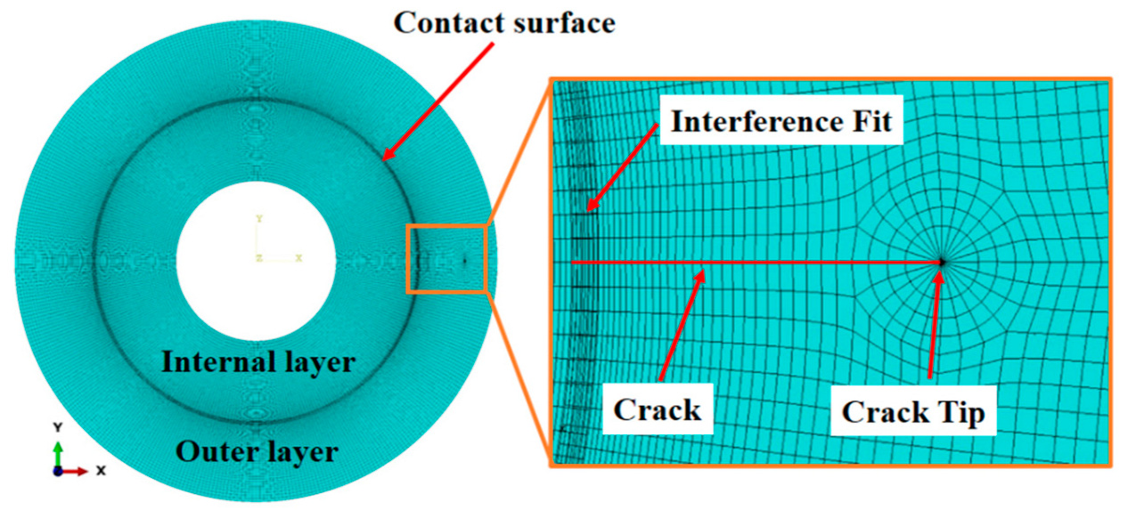
The finite element method can be used to solve the SIFs for cracks in complex special-shaped parts, and the results are relatively accurate. Using ABAQUS finite element software, an 2D finite element model of the two thick-walled cylinders with a radial crack on the inner surface of the interface is established. Only elastic deformation is considered, and the surface friction is ignored [12]. Figure 2 shows the meshed model, and Table 1 presents the parameters.
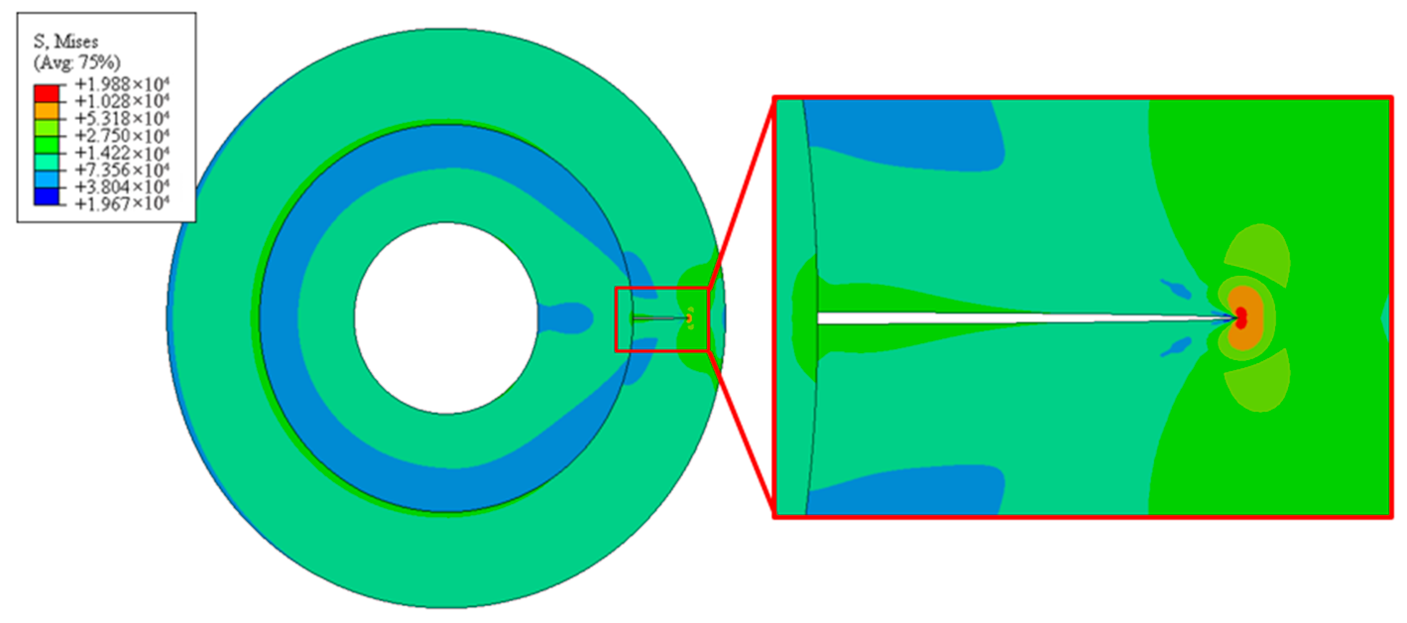
The stress nephogram of the crack, the contact pressure after the crack opening, and the SIFs of the crack on the cylinder’s inner surface under various parameters are obtained by finite element analysis, as shown in Figure 3, Figure 4 and Figure 5. In Figure 3, the maximum stress in the model appears at the crack tip region, and the stress fans out in the region. The crack opening is constrained by the inner layer of the cylinder; thus, the great stress concentration appears at the two crack surface ends, the stress decreases sharply along the interface, then increases, and tends to be stable.
Figure 4 shows the contact pressure of the interface after the crack opening at different crack depths. In the figure, the beginning of line is the contact pressure at the end of the crack’s upper surface, and the end of the line is the crack’s lower surface. The opening of the crack end is interfered with by the inner layer of the cylinder; thus, the contact pressure at both ends of the crack is high. The contact pressure initially sharply decreases, then rises gradually to a stable value due to the local deformation of the crack end. When the crack opens, the inner diameter of the thick-walled cylinders increases, and the magnitude of interference decreases slightly; therefore, the steady part of the contact pressure of thick-walled cylinders with a crack is less than that of thick-walled cylinders without a crack. The steady part of contact pressure decreases with the increase in crack depth.
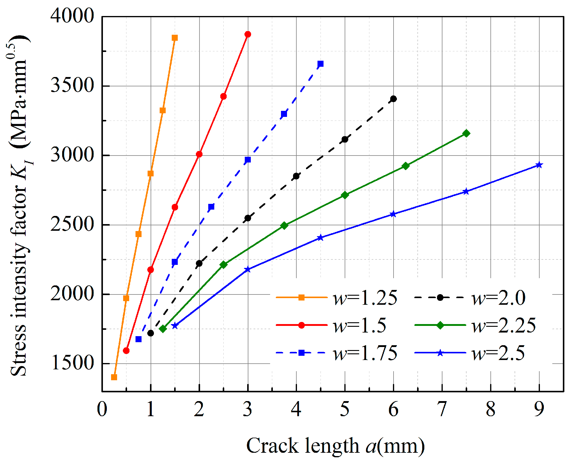
Figure 5 shows the SIFs of a crack on the inner surface of the interface with two thick-walled cylinders under interference fit. The SIF increases when the length of the initial crack increases; however, the growth trend decreases when the thickness ratio w increases. When the crack lengths are the same, the SIF decreases when the thickness ratio w increases. Detailed values are shown in Appendix A.
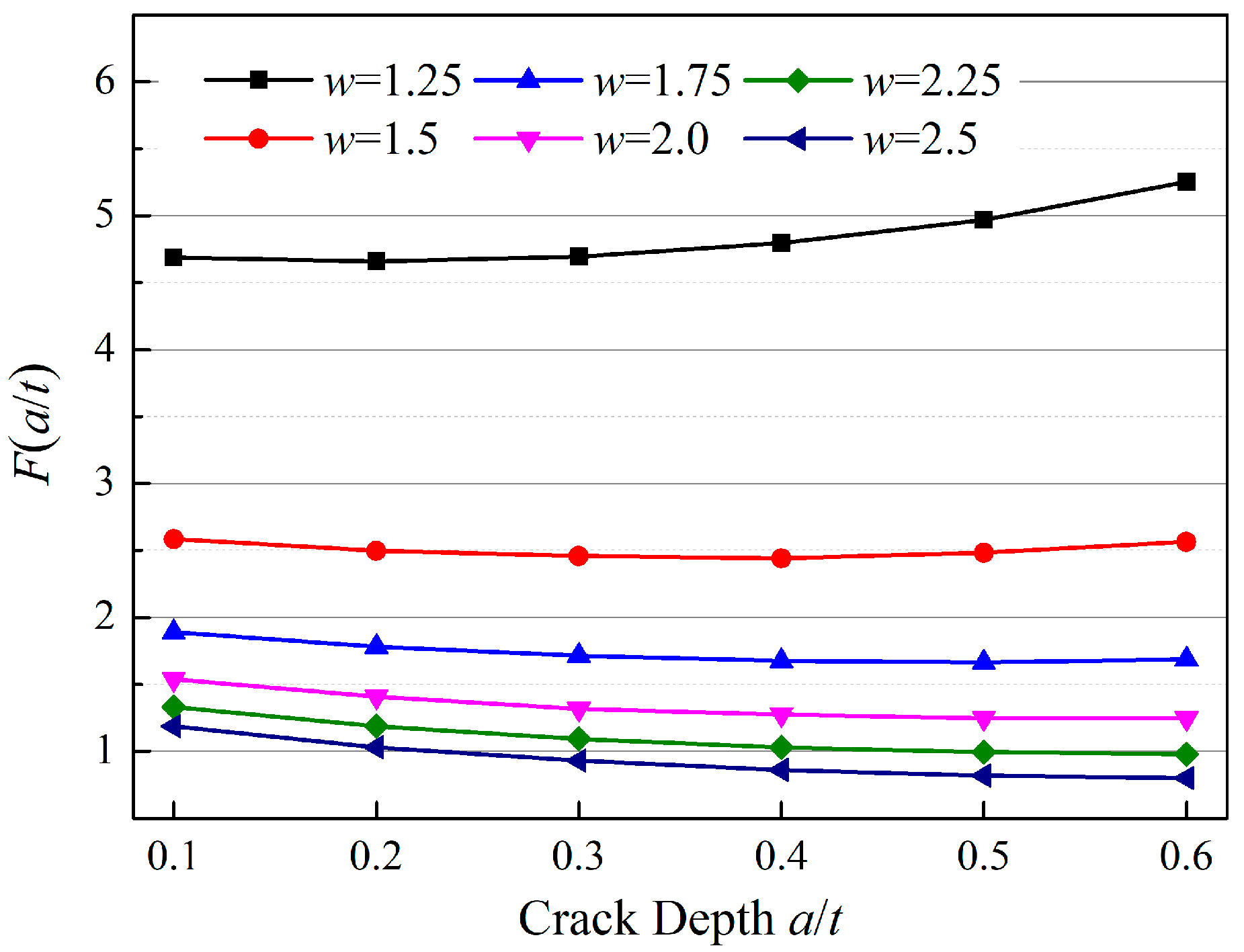
Figure 6 shows the trend of parameter F(a/t) with different crack depths and different thickness ratios w. At the same crack depth, F(a/t) decreases rapidly when the thickness ratios increase. When the thickness ratio w = 1.5, F(a/t) increases, the in crack depth also increases. For w = 1.5, F(a/t) has a slight downward trend with the increase in crack depth. When the crack depth is a/t = 0.4, the trend becomes flat. When w increases, F(a/t) decreases monotonously with the increase of the crack depth.
To show the difference between SIFs in this paper and previous studies, the SIFs in Appendix A are compared with those in Reference [33] for the thick-walled cylinders with an inner surface crack under internal pressure. Figure 7 shows the comparison of SIFs, which compared the simulation results in this paper with the calculation results of the model in Reference [33]. Table 2 presents detailed parameters, where the contact pressure can be calculated by the displacement compatibility method mentioned in Reference [34]. In Figure 7, the SIFs of the crack on the interface are always smaller than those of the inner surface crack under constant pressure. Two main reasons are given for this situation. First, the crack on the interface of the outer layer opens under the action of tangential stress, which enlarges the inner diameter of the outer layer cylinder. Thus, the interference fit and contact pressure are reduced. Second, the interference of the outer surface of the inner layer of the cylinder further prevents the crack from opening, thus reducing the stress level at the crack tip; therefore, the structure of the interface crack of the thick-walled cylinder under interference fit is different from that found in the previous literature. All existing models cannot be applied to the model of the interface crack under interference fit.
The above analysis indicates that a model of the SIFs for the interface crack needs to be rebuilt to obtain the SIF for the inner surface crack of the interface of a MRWC. According to the data in Figure 5, a fitting equation for the SIF of the crack on the inner surface of the interface of two thick-walled cylinders under interference fit can be established as:
where P is the contact pressure on the interface with no crack which can be obtained by the displacement coordination method in Reference [33]. , .
2.3. Stress Distribution of MRWC
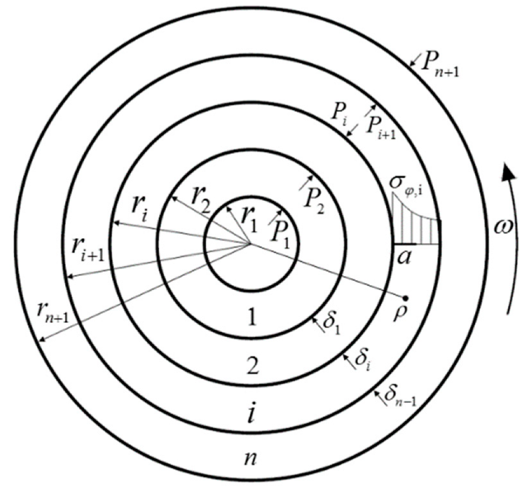
Figure 8 shows a MRWC with a crack on the inner surface of its interface. In the figure, the multi-layered, thick-walled cylinder is assembled by interference fit with n layers in the thick-walled cylinder. When the multi-layered thick-walled cylinder, without cracks, rotates at an angular speed ω, the inner surface of the ith layer of the thick-walled cylinder is subjected to contact pressure Pi under the combined action of interference fit and rotational inertia. The outer surface is subjected to contact pressure Pi+1. The tangential stress is produced by two contact pressures and rotating inertia. When a crack of length a appears on the inner surface of the ith layer of the thick-walled cylinder, the crack would open under the action of tangential stress, and a singular stress field is formed at the crack tip.
Equation (2) shows that stress distribution σφ(x) needs to be obtained when the weight function is used to solve the SIF. According to Lame’s equation, when a multi-layered thick-walled cylinder rotates, the displacement ui,ρ of any point ρ of the ith layer of the cylinder with inertia force and internal and external pressure can be calculated as [34]:
The tangential stress σφi,ρ and radial stress σPi,ρ at any point ρ in the ith layer of the cylinder are:
where μi is the Poisson’s ratio of the ith layer cylinder material, ρi is the material density of the ith layer of the cylinder, ω is the rotating speed of the cylinder, and Ai and Bi are the unknown constants of the ith layer cylinder material.
The contact pressures on the inner and outer surface of the ith layer are Pi and Pi+1, respectively. When ρ = ri, the radial stress σPi,ri is −Pi. When ρ = ri+1, the radial stress σPi+1,ri+1 is Pi+1. These values are then substituted into Equation (7) and the unknown constants Ai and Bi can be expressed as:
Equations (8) and (9) are substituted into Equations (5) and (6) to obtain tangential stress σφi,ρ and radial stress σPi,ρ of the any point ρ in the ith layer of the cylinder:
Assuming that the interface of the cylinder does not separate under centrifugal force, the displacement difference between the outer surface of the ith layer and the inner surface of the (i + 1)th layer is the magnitude of interference δi between the two layers; therefore,
P1 and Pn+1, which are external loads, are known conditions; therefore, the values of the contact pressure P2–Pn can be calculated by the linear equations in Equation (12). The tangential stress σφi,ρ of the ith layer in Equation (11), which is the σθ(x) in Equation (2), can be obtained by substituting the contact pressure Pi and Pi+1 of the ith layer of the cylinder into Equation (11). The x in σθ(x) is the distance from a point on the crack of the ith layer to the inner surface, so x = ρ − ri.
2.4. Solution of SIF by Weight Function
To solve SIF by using the weight function, the crack face displacement u(a, x) of the cracked structure must be obtained first. The crack face displacement u(a, x) in Equation (3) can be expressed as [33]:
where G(a/t) is an unknown constant, and the complete boundary correction factor F(a/t) can be obtained by substituting Equation (4) into Equation (1).
Therefore,
where C is the symbol used to simplify the equation, that can be calculated as follows:
where is wall thickness ratio, t is the thickness of the wall as follows:
Setting KI = KIC, R2 = ri, R3 = ri+1 in Equations (1) and (2), G(a/t) in Equation (13) can be solved as:
where I can be expressed as:
The tangential stress distribution function σφ(x) along the crack direction and the tangential stress σθ of the interface without cracks under interference fit can be expressed as [34]:
With Equations (13) and (1) substituted into Equation (3), the weight function h(a, x) can be solved as:
F and G are simplified symbols of F(a/t) and G(a/t), respectively. and are derivatives of F(a/t) and G(a/t) to a, respectively. Then, using Equation (14), Equation (17), and (18), the derivation of I1, I2, and I3 from Equation (18) to a are obtained:
with Equations (11) and (22) substituted into Equation (2), the equation for calculating the SIF KIC of the crack on the interface of MRWC can be obtained:
3. Results and Discussion
To verify Equation (31) for the SIF, ABAQUS finite element software is used to analyze the MRWC with a radial crack on the inner surface of the interface. The crack is a penetrating crack, thus, 2D plane finite element models are established to save calculation time. As shown in Figure 9a, the 2D plane model consists of thick-walled cylinders with four-layers under interference fit. Table 3 shows the parameters of the multi-layered thick-walled cylinders. A radial penetrating crack with a crack depth of a/t = 0.1–0.6 is presented on the inner surface of the third layer. In the finite element model, the boundary conditions restrict the tangential displacement in the radius direction of the thick-walled cylinder. Rotating body force is applied on the 2D finite element models to simulate the rotation of the multi-layered thick-walled cylinder. In the finite model, the contact surfaces are frictionless, and all deformations are elastic. The model applies the boundary conditions, as shown in Figure 9b.
The stress nephogram of a crack with a length of 10 mm is obtained by finite element analysis, as shown in Figure 10. In the figure, the maximum stress at the crack tip far exceeds the stress produced by the interference fit because of the singularity of the crack; thus, the overall stress nephogram is mostly blue and green. The maximum stress is located at the crack tip, the stress field is red and yellow, and the maximum stress is 7270 Mpa. The crack opening is hindered by the outer surface of the internal layer of the thick-walled cylinder; thus, the concentrated stress appears at the end of the crack.
To verify the accuracy of the finite element models, the contact pressure calculated by Equation (12) is used to verify the contact pressure of the three contact surfaces in a rotating thick-walled cylinder with four-layers without cracks. In the finite element model, the contact pressure P2 of the first layer and the second layer is 187 Mpa. The contact pressure P3 of the second layer and the third layer is 165 Mpa, and the contact pressure P4 of the third and fourth layers is 47 MPa. The contact pressures P2–P4 calculated by Equation (12) are 186, 165, and 44.7 Mpa, respectively. The contact pressure calculated by the finite element model is approximately equal to that calculated by Equation (12); therefore, the accuracy of the finite element model can be verified.
The crack face displacement u(a, x) is the most important parameter in the SIF equation, which directly affects the results of the SIFs. The finite element models and Equation (13) were compared to verify the crack face displacement u(a, x) in the weight function. The finite element model is shown in Figure 9, with a crack length of 10 mm. The measured displacement is the distance between the upper and the lower surfaces of the crack in the same location; the measured starting position is the crack initiation, which is near the interface. The model calculated by Equation (13) is symmetrical; thus, the obtained crack face displacement should be twice as large. Table 4 presents the comparison results. The maximum relative error between the results of Equation (13) and the finite element model is 3.4%, which is a small value, thereby showing that the derived equation is accurate.
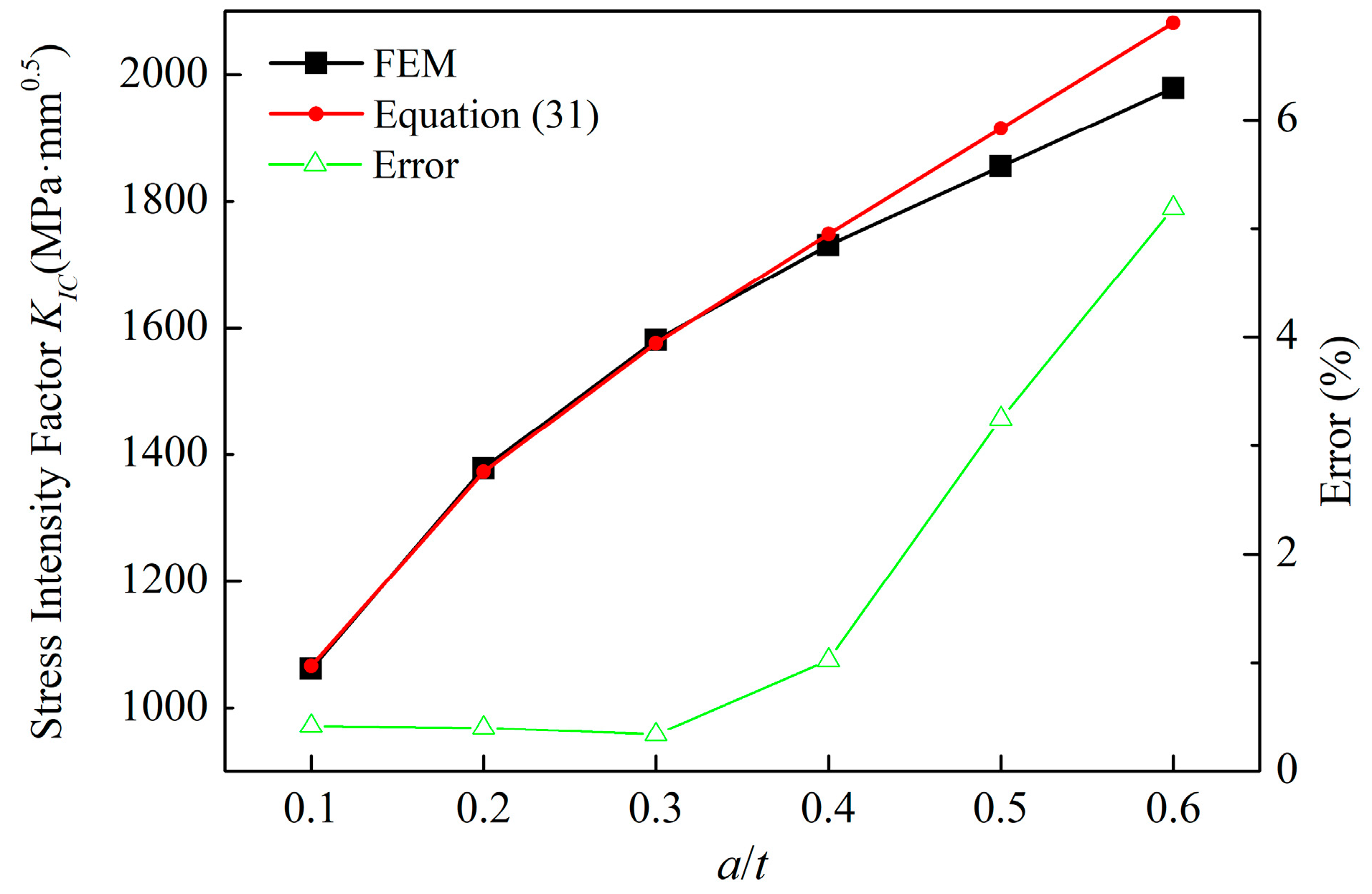
Figure 11 shows the comparison of the SIFs of the two models. When the relative crack depth is a/t = 0.1–0.4, the relative error is less than 1%. When the depth is a/t = 0.4–0.6, the error increases gradually and the maximum error is 5%. The main reason for this condition is the fitting effect of Equation (4); however, the error is within a acceptable range, thus meeting the requirements for solving the SIF.
4. Conclusions
In this paper, an equation of SIF was developed for a radial penetrating crack on the inner surface of the interface of a MRWC by the finite element method and weight function method, which are used to describe the development state of the crack of multi-layered rotating thick-walled cylinder in any layer. The main conclusions are as follows:
1. The finite element models for two thick-walled cylinders with a radial crack on the interface under interference fit were established by ABAQUS finite element software, which used to establish shape parameters. According to the simulation results, the SIF equation for the crack with two parameters of crack depth and wall thickness ratio is obtained by using the fitting method, which has high calculation accuracy. The applicable range of the equation is a crack depth a/t = 0.1–0.6 and a wall thickness ratio w = 1.25–2.5. The fitting results show that the SIF increases with an increase in crack length, and the growth rate decreases with the thickness ratio. When the crack length is the same, increasing the thickness ratio will reduce the SIF of the crack.
2. The tangential stress distribution equation of any layer of a MRWC is established. The weight function h(a, x) of SIF for cracks on the inner surface of the interface of a multi-layered thick-walled cylinder is derived by the fitting Equation (4). Then, the SIF Equation (31) for a radial penetrating crack on the inner surface of the interface of a MRWC is obtained by the 2D weight function method. The mathematical model established in this paper can calculate the SIF of an inner interface crack in any layer of a multi-layered rotating thick-walled cylinder, which has a high calculation accuracy and is convenient for engineering applications.
3. The finite element models of the rotating thick-walled cylinders with four-layers with a crack are established by using ABAQUS. The crack face displacement, the SIFs of the finite element models, and the equations, are compared in order to verify the accuracy of theoretical deduction. The maximum relative error of the crack face displacement between the two methods is 3.4%, and the maximum relative error of SIF is 5%; therefore, SIF Equation (31) obtains an accurate expression of the radial penetrating crack on the inner surface of the interface of an MRWC.
Author Contributions
Conceptualization, methodology, data curation, software, validation writing—original draft, editing, J.Y.; supervision, project administration, funding acquisition, Z.Y.; review and editing, supervision, C.C.; review and editing, supervision, H.T.; review and editing, F.D.; modification suggestion, J.L. All authors have read and agreed to the published version of the manuscript.
Funding
This research was funded by National Natural Science Foundation of China (Grant No. 51975249), Key Research and Development Plan of Jilin Province (Grant No. 20190302017GX), Project of Jilin Provincial Department of Education (Grant No. JJKH20220985KJ), Shenzhen Peacock Plan of Shenzhen Science and Technology Program (Grant No. KQTD2016113010470345), Guangdong Provincial Department of Education of China (Grant 2019KZDZX1025), Innovative Program for Graduate Education (Grant No. 503170060259), School-enterprise Cooperation Projects HX19029, HX20199, HX20247, HX21008 from Wuyi University, Fundamental Research Funds for the Central Universities, and finally, the paper is supported by JLUSTIRT.
Institutional Review Board Statement
Not applicable.
Informed Consent Statement
Not applicable.
Data Availability Statement
Not applicable.
Conflicts of Interest
The authors declare no conflict of interest.
Appendix A

Table A1.
Stress intensity factors with two parameters.
| w | 1.25 | 1.5 | 1.75 | 2 | 2.25 | 2.5 |
|---|---|---|---|---|---|---|
| a/t | ||||||
| 0.1 | 1402 | 1594 | 1675 | 1719 | 1752 | 1774 |
| 0.2 | 1970 | 2177 | 2232 | 2222 | 2213 | 2180 |
| 0.3 | 2432 | 2626 | 2630 | 2548 | 2495 | 2408 |
| 0.4 | 2868 | 3009 | 2969 | 2851 | 2715 | 2577 |
| 0.5 | 3323 | 3424 | 3298 | 3115 | 2924 | 2740 |
| 0.6 | 3847 | 3871 | 3659 | 3407 | 3159 | 2932 |
References
- Yazdanmehr, A.; Soltani, N. Evaluation of stress intensity factors of rounded V and U notches under mixed mode loading, using the experimental method of caustics. Theor. Appl. Fract. Mech. 2014, 74, 79–85. [Google Scholar] [CrossRef]
- Li, D.F.; Mao, Z.H. Experimental and numerical simulations on compound stress intensity factor of semi-elliptical cracks on the exchanger outer walls with inclined angles. Alex. Eng. J. 2022, 61, 5065–5072. [Google Scholar] [CrossRef]
- Jukic, K.; Peric, M.; Tonkovic, Z.; Skozrit, I.; Jarak, T. Numerical Calculation of Stress Intensity Factors for Semi-Elliptical Surface Cracks in Buried-Arc Welded Thick Plates. Metals 2021, 11, 1809. [Google Scholar] [CrossRef]
- Jin, X.; Zeng, Y.; Ding, S.; Zhang, B.; McLennan, J.; Roegiers, J.-C.; Shah, S.; Bian, X. Weight function of stress intensity factor for single radial crack emanating from hollow cylinder. Eng. Fract. Mech. 2017, 170, 77–86. [Google Scholar] [CrossRef]
- Boljanovic, S.; Maksimovic, S. Fatigue crack growth modeling of attachment lugs. Int. J. Fatigue 2014, 58, 66–74. [Google Scholar] [CrossRef]
- Gairola, S.; Jayaganthan, R. XFEM Simulation of Tensile and Fracture Behavior of Ultrafine-Grained Al 6061 Alloy. Metals 2021, 11, 1761. [Google Scholar] [CrossRef]
- Bowie, O.L. Analysis of an Infinite Plate Containing Radial Cracks Originating at the Boundary of an Internal Circular Hole. Stud. Appl. Math. 1956, 35, 60–71. [Google Scholar] [CrossRef]
- Bowie, O.L.; Freese, C.E. Elastic analysis for a radial crack in a circular ring. Eng. Fract. Mech. 1972, 4, 312–321. [Google Scholar] [CrossRef]
- Newman, J.C. Predicting Failure of Specimens with Either Surface Cracks or Corner Cracks at Holes. NASA TN D-8244; 1976. Available online: https://ntrs.nasa.gov/api/citations/19760019499/downloads/19760019499.pdf (accessed on 8 April 2022).
- Kirkhope, K.J.; Bell, R.; Kirkhope, J. Stress intensity factor equations for single and multiple cracked pressurized thick-walled cylinders. Int. J. Press. Vessel. Pip. 1990, 41, 103–111. [Google Scholar] [CrossRef]
- Chen, A.; Liao, L.; Zhang, D. Analysis of dynamic stress intensity factors of thick-walled cylinder under internal impulsive pressure. Acta Mech. Sin. 2009, 25, 803–809. [Google Scholar] [CrossRef]
- Chen, X.; You, Y. Weight functions for multiple axial cracks in a coated hollow cylinder. Arch. Appl. Mech. 2015, 85, 617–628. [Google Scholar] [CrossRef]
- Yue, F.; Wu, Z. Fracture Mechanical Analysis of Thin-Walled Cylindrical Shells with Cracks. Metals 2021, 11, 592. [Google Scholar] [CrossRef]
- Niasani, M.A.; Ghajar, R.; Googarchin, H.S.; Hossein Sharifi, S.M. Crack growth pattern prediction in a thin walled cylinder based on closed form thermo-elastic stress intensity factors. J. Mech. Ence Technol. 2017, 31, 1603–1610. [Google Scholar] [CrossRef]
- Eshraghi, I.; Soltani, N.; Rajabi, M. Transient Stress Intensity Factors of Functionally Graded Hollow Cylinders with Internal Circumferential Cracks. Lat. Am. J. Solids Struct. 2016, 13, 1738–1762. [Google Scholar] [CrossRef] [Green Version]
- Wang, Z.Y.; Shi, Y.Z.; Zhou, X.F.; Shao, Y.B. Assessment of surface crack growth of composite girders with concrete-filled tubular flanges and corrugated webs through substructure-based numerical modelling. Eng. Struct. 2022, 252, 113613. [Google Scholar] [CrossRef]
- Shahani, A.R.; Habibi, S.E. Stress intensity factors in a hollow cylinder containing a circumferential semi-elliptical crack subjected to combined loading. Int. J. Fatigue 2007, 29, 128–140. [Google Scholar] [CrossRef]
- Takase, Y.; Noda, N.-A. Convenient and accurate formulas for stress intensity factor distribution of semi-elliptical surface crack. Int. J. Mod. Phys. B 2021, 35, 2140002. [Google Scholar] [CrossRef]
- Tan, P. Numerical simulation of the ballistic protection performance of a laminated armor system with pre-existing debonding/delamination. Compos. Part B Eng. 2014, 59, 50–59. [Google Scholar] [CrossRef]
- Kolanu, N.R.; Raju, G.; Ramji, M. A unified numerical approach for the simulation of intra and inter laminar damage evolution in stiffened CFRP panels under compression. Compos. Part B Eng. 2020, 190, 107931. [Google Scholar] [CrossRef]
- Rozylo, P. Failure analysis of thin-walled composite structures using independent advanced damage models. Compos. Struct. 2021, 262, 113598. [Google Scholar] [CrossRef]
- Afsar, A.M.; Anisuzzaman, M. Stress intensity factors of two diametrically opposed edge cracks in a thick-walled functionally graded material cylinder. Eng. Fract. Mech. 2007, 74, 1617–1636. [Google Scholar] [CrossRef]
- Nami, M.R.; Eskandari, H. Three-Dimensional Investigations of Stress-Intensity Factors in a Cracked Cylinder Made of Functionally Graded Materials. Mech. Based Des. Struct. Mach. 2012, 40, 206–217. [Google Scholar] [CrossRef]
- Mirahmadi, H.; Azimi, M.; Mirjavadi, S.S. Calculation of stress intensity factor for functionally graded cylinders with two radial cracks using the weight function method. Theor. Appl. Fract. Mech. 2016, 85, 447–456. [Google Scholar] [CrossRef]
- Nojumi, M.M.; Wang, X. Analysis of crack problems in functionally graded materials under thermomechanical loading using graded finite elements. Mech. Res. Commun. 2020, 106, 103534. [Google Scholar] [CrossRef]
- Miura, K.; Sakamoto, M.; Tanabe, Y. Analytical solution for the axisymmetric problem of a penny-shaped crack under internal pressure in a multi-layer composite. Mech. Eng. J. 2021, 8, 21–25. [Google Scholar] [CrossRef]
- Chen, X.; Mai, Y.W. Fundamentals of Fracture Mechanics; Butterworth: London, UK, 1973. [Google Scholar]
- Ramezani, M.K.; Purbolaksono, J.; Andriyana, A.; Ramesh, S.; Mardi, N.A. Analysis of surface cracks in round bars using dual boundary element method. Eng. Anal. Bound. Elem. 2018, 93, 112–123. [Google Scholar] [CrossRef]
- Rice, J.R. Some remarks on elastic crack-tip stress fields. Int. J. Solids Struct. 1972, 8, 751–758. [Google Scholar] [CrossRef] [Green Version]
- Petroski, H.J.; Achenbach, J.D. Computation of the weight function from a stress intensity factor. Eng. Fract. Mech. 1978, 10, 257–266. [Google Scholar] [CrossRef] [Green Version]
- Glinka, G.; Shen, G. Universal features of weight functions for cracks in mode I. Eng. Fract. Mech. 1991, 40, 1135–1146. [Google Scholar] [CrossRef]
- Alshoaibi, A.M.; Fageehi, Y.A. Simulation of Quasi-Static Crack Propagation by Adaptive Finite Element Method. Metals 2021, 11, 98. [Google Scholar] [CrossRef]
- Chen, A.J.; Zeng, W.J. Weight function for stress intensity factors in rotating thick-walled cylinder. Appl. Math. Mech.-Engl. Ed. 2006, 27, 29–35. [Google Scholar] [CrossRef]
- Kassir, M. Applied Elasticity and Plasticity; CRC Press: Boca Raton, FL, USA, 2017. [Google Scholar]
Figure 1.
Two thick-walled cylinders with a radial crack.

Figure 2.
Finite element model with a crack.

Figure 3.
Stress nephogram of a crack (R3 = 15 mm, crack depth = 0.6).

Figure 4.
Contact pressure of cylinders with crack (R3 = 15 mm).

Figure 5.
SIFs of different cracks.

Figure 6.
Trend of the correction factor F(a/t) with the crack depth.

Figure 7.
Comparison of two SIFs.

Figure 8.
MRWC with an interface crack.

Figure 9.
2D finite element model. (a) The 2D plane model consists of thick-walled cylinders with four-layers under interference fit. (b) The model applies the boundary conditions.
Figure 9.
2D finite element model. (a) The 2D plane model consists of thick-walled cylinders with four-layers under interference fit. (b) The model applies the boundary conditions.

Figure 10.
The stress nephogram of crack.

Figure 11.
Comparison of stress intensity factor.

Table 1.
Parameters of finite element model.
| Parameter | Value |
|---|---|
| Elastic modulus E | 210,000 MPa |
| Poisson’s ratio μ | 0.3 |
| Type of element | CPE8R |
| Type of crack tip element | CPS6 |
| Method for calculating SIF | Contour integral |
| Mid-side node parameter | 0.25 |
| Number of contours | 4 |
| Crack initiation criterion | Maximum tangential stress |
| Internal diameter of the internal layer R1 | 5 mm |
| Outside diameter of the internal layer R2 | 10 mm |
| Outside diameter of the outer layer R3 | 12.5 mm~25 mm |
| Thickness ratio w (R3/R2) | 1.25~3 |
| Crack depth a/t | 0.1~0.6 |
| Magnitude of interference δC | 0.1 mm |
Table 2.
Parameters of finite element model.
| Parameter | Cracks of Interface | Reference [33] |
|---|---|---|
| Inner diameter of internal layer | 5 mm | None |
| Outer diameter of internal layer | 10.1 mm | None |
| Inner diameter of outer layer | 10 mm | 10 mm |
| Outer diameter of outer layer | 15 mm | 15 mm |
| Pressure | Contact pressure 492 MPa | Constant pressure 492 MPa |
| Crack depth (a/t) | 0.1~0.5 | 0.1~0.5 |
Table 3.
Thick-walled cylinder parameters.
| Parameters | First Layer | Second Layer | Third Layer | Fourth Layer |
|---|---|---|---|---|
| Inner diameter (mm) | 10 | 20 | 30 | 60 |
| Outer diameter (mm) | 20.05 | 30.08 | 60.1 | 80 |
| Elasticity modulus (MPa) | 1 × 10⁵ | 1.5 × 10⁵ | 1.8 × 10⁵ | 2.1 × 10⁵ |
| Poisson’s ratio | 0.3 | 0.27 | 0.34 | 0.3 |
| Density (T/mm) | 7.8 × 10⁻⁸ | 8.8 × 10⁻⁸ | 6.8 × 10⁻⁸ | 5.8 × 10⁻⁸ |
| Rotation speed (rad/s) | 1000 | 1000 | 1000 | 1000 |
Table 4.
Results comparison.
| x mm | 0 | 0.94 | 1.97 | 2.98 | 3.98 | 4.98 | 5.98 | 6.99 | 7.99 | 8.98 | |
|---|---|---|---|---|---|---|---|---|---|---|---|
| FEM (μm) | Diaplace | 37.6 | 37.3 | 36.2 | 34.6 | 32.7 | 30.4 | 27.6 | 24.2 | 20.0 | 14.3 |
| Equation (13) (μm) | Diaplace | 38.9 | 37.6 | 36 | 34.2 | 32 | 29.9 | 27.1 | 23.8 | 19.8 | 14.3 |
| Error % | 3.4 | 0.6 | 0.6 | 1.4 | 2.3 | 1.8 | 2 | 1.9 | 1.1 | 0 |
Publisher’s Note: MDPI stays neutral with regard to jurisdictional claims in published maps and institutional affiliations. |
© 2022 by the authors. Licensee MDPI, Basel, Switzerland. This article is an open access article distributed under the terms and conditions of the Creative Commons Attribution (CC BY) license (https://creativecommons.org/licenses/by/4.0/).
Share and Cite
MDPI and ACS Style
Ying, J.; Yang, Z.; Chen, C.; Tian, H.; Deng, F.; Li, J. Stress Intensity Factors for Radial Crack on Inner Surface of Interface in Multi-Layer Rotating Thick-Walled Cylinder. Metals 2022, 12, 858. https://doi.org/10.3390/met12050858
AMA Style
Ying J, Yang Z, Chen C, Tian H, Deng F, Li J. Stress Intensity Factors for Radial Crack on Inner Surface of Interface in Multi-Layer Rotating Thick-Walled Cylinder. Metals. 2022; 12(5):858. https://doi.org/10.3390/met12050858
Chicago/Turabian StyleYing, Jun, Zhaojun Yang, Chuanhai Chen, Hailong Tian, Fuqin Deng, and Jieli Li. 2022. "Stress Intensity Factors for Radial Crack on Inner Surface of Interface in Multi-Layer Rotating Thick-Walled Cylinder" Metals 12, no. 5: 858. https://doi.org/10.3390/met12050858
Note that from the first issue of 2016, this journal uses article numbers instead of page numbers. See further details here.