
A Trolley Wire De-Icing System

Department of Electrical Power Engineering, Power Electronics and Electrical Machines, Kielce University of Technology, 25-314 Kielce, Poland
*
Author to whom correspondence should be addressed.
Energies 2022, 15(18), 6832; https://doi.org/10.3390/en15186832
Submission received: 12 August 2022
/
Revised: 15 September 2022
/
Accepted: 16 September 2022
/
Published: 19 September 2022
(This article belongs to the Special Issue Power Quality Analysis and Control of Railway Power Supply Systems)
Abstract
:This paper presents a dedicated system for de-icing trolley wires. The proposed issue is appropriately under the protection of intellectual property for solving as described in patent no.B1 230665 PL in the Patent Office of the Republic of Poland. In the solution presented herein, de-icing is achieved mainly by electrodynamic force excitation and secondarily as a result of heating. Because ice is removed primarily through vibrations, it avoids a large consumption of electricity associated with the high specific heat of water. More importantly, operation is nearly simultaneously applied to the total distance of the trolley power grid between two substations. For this reason, it requires less electricity consumption and less time to apply than in heating, mechanical, or chemical methods.
1. Introduction
To maintain the safety of railway traffic in the winter season, the main obstacle is freezing of the railroad switches and icing of the trolley wires. Various techniques are currently employed to solve this problem that are manual, chemical, and electric [1]. The last entails the prohibitive costs of electricity required for the task [2].
In winter, under some particular weather conditions, the surface of trolley wires is covered by a layer of ice. This causes some difficulties and can sometimes leads to serious damage. Sublimated water in the form of ice on the wires can significantly increase the load of traction poles. In critical situations, it can lead to damage of trolley wires and catenaries, sometimes pylons as well.
When trolley wires are covered by ice, the electrical contact between the pantograph and the wires worsens. This results in electric arcing between the pantograph and wires, energy losses and strong electromagnetic interference. Electric arcs partially melt the contact surface between the pantograph and the trolley wires.
Over the years, different de-icing methods for trolley wires have been developed. Methods to avoid icing by covering the surface of the wire with an anti-condensation substance have been tried [3,4]. The heating of wires to remove the ice have also been proposed. Methods relying on mechanical vibrations generated by a system of special hammers installed on the locomotive roof have been developed. The proposed methods have a number of bottlenecks. To cover the surface of the wires with an anti-condensation coating, it is necessary to send round a special locomotive at low speed. The anti-condensation layer has no immunity to abrasion and the coating must be reapplied from time to time. To melt the ice, a large amount of energy is needed due to the heat of fusion of ice. Moreover, if the water is not removed it can turn back into ice. A method of de-icing that uses electrodynamic force has been proposed for power transmission lines [5,6]. In this case, very large values of short currents are required to produce enough exciting force due to the long distances between the wires. Therefore, this kind of method is proposed only for critical cases.
2. Method of De-Icing of Trolley Wires
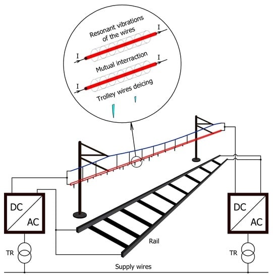
In Poland and other countries with DC traction supplied by a voltage of approximately 3 kV, most of the main electric traction lines have double trolley wires, consisting of two component wires spaced 0.1 m from each other. The fact, that the wires are in close proximity to each other makes it possible to excite an electrodynamic force of significant value. This force may be used to put parts of the trolley power grid into a controlled resonant state. Until now, no one has considered the possibility of using this phenomenon for de-icing trolley wires. Figure 1 shows the structure of the de-icing system [7], where 1, 2—supply stations, 3, 4, 5, 6—supply wires, 7—trolley wires, 8—railway trucks, 9, 10—rail connections.
Patent no. [7] presents a method for de-icing trolley wires. In the proposed method, de-icing is achieved by generating mechanical vibrations in the trolley wires, carrier line, and their connections. Vibrations are excited by electrodynamic force between two trolley wires.
1, 2—supply stations, 3, 4, 5, 6—supply wires, 7—trolley wires, 8—railway trucks, 9, 10—rail connections, 11, 12—electric transformers, 13—electric grid, 14, 15—transformer connections, 16, 17—power electronic converter, 18—accelerometer sensor, 19—hanger, 20—camera, 21—carrier line, 22—contactor (only Figure 3).
A system with two supply stations, shown in Figure 2, may function without additional contactors, but it does demand bidirectional energy flow in the supply stations. Additionally, the power from the supply stations, especially the rectifier station, must be significant. This is because electricity circulates from the power grid through the rectifier station, connecting in parallel the trolley wires and carrier line, and then returns to the power grid through the inverter station. Such a system should be considered as a future solution when multi-level, low-current distortion, high-power-factor substation rectifiers will be able to handle regenerative braking of trains by transferring the energy to the power grid.
A system with one supply station, shown in Figure 3, needs an additional contactor 22, but the power of the rectifier station may be significantly reduced. This is because electricity flows from the power grid through the rectifier station and supplies only the trolley wires and carrier line, connected in parallel. The primary source of mechanical force that sets the trolley wires in motion is the electrodynamics force that appears between two parallel trolley wires. Such a system is a potential contemporary solution.
A mobile system with a supply power converter installed on the locomotive is also a possible solution. Figure 4 illustrates the physical principle of electrodynamic force generation in a system of two parallel wires conducting a current.
Since the trolley wires and carrier line are connected in parallel, their currents flow in the same direction. For this reason, force pull the wires toward each other and changes according to the square of the current and in an inverse proportion to the distance between them, pulling toward the trolley wires and carrier line. The magnetic flux density B (1) is proportional to the electric current i of the trolley grid:
where μ0 is the permeability of free space and r is the distance between the two wires.
The electromagnetic force (2) is proportional to the magnetic flux density and the current of the trolley grid:
where l is the length of the wire.
Finally, the linear density of the electromagnetic force (3) is proportional to the square of the current supplying trolley grid:
where the coefficient AFI for the average distance of the wires (approximately 0.1 m) is:
At any cross-section of the trolley power grid, the overall current consists of two trolley currents and the carrier line current. Because they are connected by hanger wires, a portion of the current is exchanged between them (5):
where ij1 and ij2 are the currents in the two parallel trolley wires and ic is the current in the carrier line.
Assuming that current ij is composed of DC and AC harmonic components (6), the electrodynamic force per meter is expressed by Equations (7) and (8).
when then
The RMS value of current (9) is responsible for heating the wires.
The values chosen for DC current and the amplitude of AC current determine the electrodynamic force amplitude and RMS current value. Thus, the proportion between the shaking and heating of the wires can be regulated.
3. Model of a De-Icing System
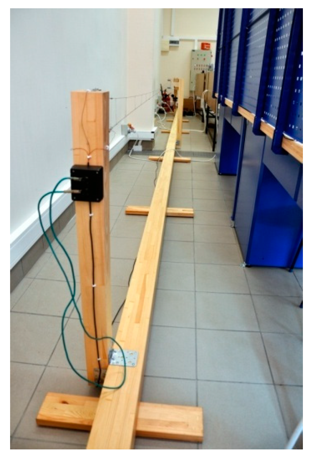
Figure 5 and Figure 6 show a model of this de-icing system built to verify the proposed de-icing method. The model consists of two spans (each of length 4.5 m) containing three transmission towers and a double trolley wire hung on a carrier line, a power converter for supplying the trolley power grid and an induction chock. The model is at a scale of 1:16.
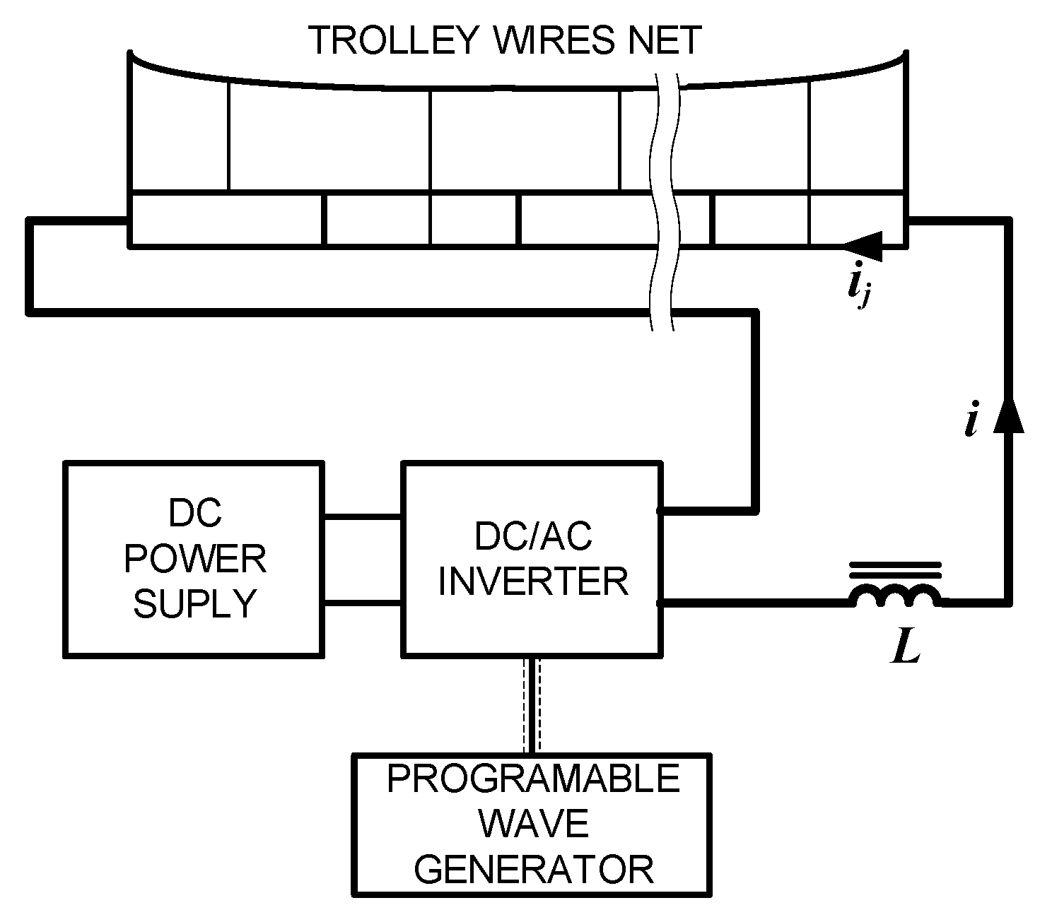
In the model, the double trolley wires and carrier line connected in parallel and hung on conducting hangers are supplied by a PWM power inverter that generates voltage containing AC and DC components. The frequency of the AC voltage component is regulated in such a manner as to cause controlled resonant vibrations of the system’s components. Figure 7 shows a block diagram of the de-icing system.
The following parameters were measured:
, , , , , .
The experimental setup shown in Figure 8 consists of a reference signal generator, a PWM modulator, a power converter, a magnetic induction chock, a DC power supply, isolated power supplies, hall current sensor, a current-measuring module, an oscilloscope, and a fan.
4. Experiment
The experimental research that has been carried out on the model relies on excitation of the system by currents of variable frequency and registration of the horizontal and vertical alignment of the wires. Mechanical vibrations were measured optically with the use of a slow-motion compact camera (Sony RX100 Mk IV). The displacement of the wires was read from photographs taken of the wires on the background of millimeter paper. The optical setup that was used for the measurements is illustrated in Figure 9a,b.
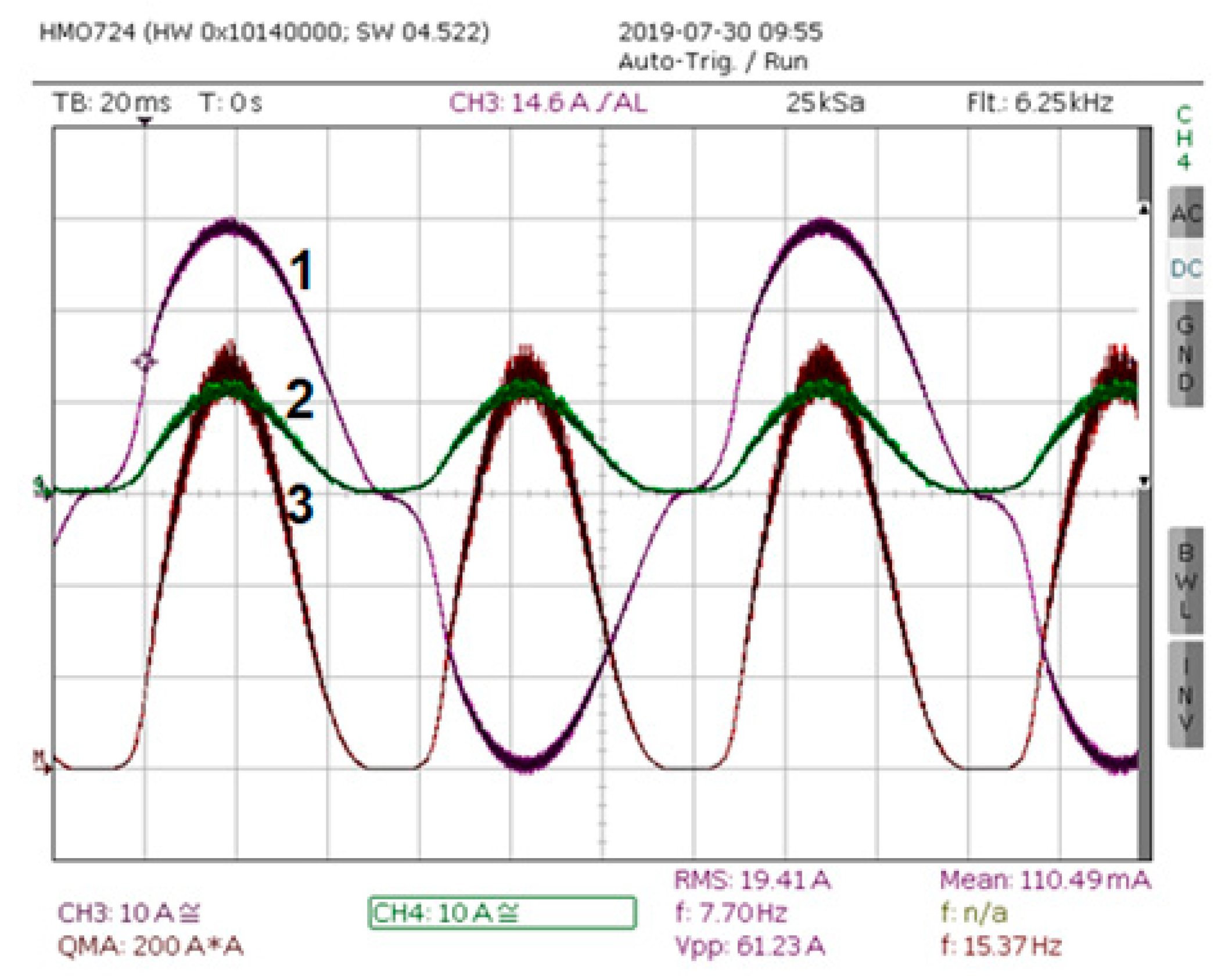
Figure 10 presents the current of the traction wires and its square along with the DC supply current. Because electrodynamic force is nearly proportional to the square of a current, it can be concluded that the registered plot of the square of a current illustrates the approximate plot of the force that excites mechanical vibrations.
Figure 11 shows the amplitude spectrum of trolley wires horizontal placement.
An analysis of the amplitude spectrum of trolley wires leads to the following conclusions:
- The most intense vibrations take place at the fundamental frequency of approximately 7.7 Hz and nearly all the energy is generated by the fundamental frequency;
- At higher frequencies, no significant maximums can be found for the amplitude spectrum.
On the basis of amplitude spectrum of the placement of trolley wires and the carrier line, one can conclude that there are some resonant frequencies of the components of a trolley power grid. At frequencies of approximately 6.5 Hz the catenary vibrates significantly, while the vibrations of trolley wires are nearly unnoticeable. At frequencies of approximately 7.6 Hz, the entire span—the trolley wires and the catenary—vibrates together. The wires are stretched in left and right positions with the greatest deviation in the middle of the span. At frequencies of approximately 10.5 Hz, the two trolley wires vibrate independently.
It can be noticed that the amplitude of vibration changes over time. This is because the mechanical parameters of the traction line model change with the temperature of the wires. The temperature depends on the RMS current value and external cooling conditions.
5. Influence of the De-icing System on the Power Grid
Power analysis:
Because the frequency of vibration is many times lower than the PWM carrier frequency (10), one can conclude that the impedance of the traction wires for current frequency is nearly resistive (11).
where —total inductance of the wires, —total resistance of the wires
For this reason, the instantaneous power value may be expressed by Equation (12).
The time plot of the instantaneous power value has a pulsating shape. Its active power value (13) depends on the average values of the current and the amplitude of the AC current component.
In order to ensure energy quality, a three-phase PFC rectifier with a high power factor and a low current total harmonic distortion should be used as the grid converter. The input impedance of the rectifier is then nearly resistive (14) and the time plot of power is nearly constant. Consequently, it means that the instantaneous input power value is nearly equal to its active power value (16).
where —grid angular frequency,
Because the instantaneous value of input power significantly differs from its active power over a longer time, it is necessary to install a buffer energy tank in the converter system. The amount of energy that should be stored in the buffer may be calculated according to Equation (17) to Equation (19).
The value of energy that should be stored in the system and passed to the load is the starting point for calculating the capacity of the energy tank. In the case of a capacitive energy tank, the difference of energy is described by Equation (20).
Then fluctuation of capacitor voltage:
It can be seen that the demands of a high change rate of energy storage coupled with requirements for low voltage fluctuation leads to a high condenser buffer capacitance (27). Figure 12 shows a storage buffer (Buf) creates an energy power electronics system with two energy storage buffers, which should be an appropriate solution to this problem. In such a system, the energy storage capacitance is divided into two units. One unit creates a DC voltage source for the converter, although its capacitance (C1, C2) has a moderate voltage change during the output voltage period that is limited to close range. This buffer is used for fast energy exchange between the power grid, the loads, and the energy storage system. For the second storage system, although its capacity is large, the voltage change is high during the period of output voltage.
6. Conclusions
A new method of de-icing trolley and carrier line wires was presented. The principle of the system’s operation was explained. A physical model of part of a traction line was assembled for experimental verification of the proposed method.
Spectrums of the vibration of components of a trolley power grid were derived from the experiments. Based on this data, one can conclude that there are a number of resonant frequencies of different parts of a trolley power grid that could be useful for de-icing. Because resonant frequencies change, in the case of variable meteorological conditions it is necessary to apply an algorithm with online optimization of vibrations. Due to the differences in built of spans, the control method should scan a frequency band for voltages that are able to excite enough vibrations to de-ice each span of the traction line. Further experimental verification should be carried out on a real traction line. The proposed method allows for the de-icing process to be applied over the entire distance of the traction line in a relatively short time.
The issues of energy quality in the power grid were considered in the paper. The requirements of energy storage were analyzed. The instantaneous power delivered to trolley wires changes over time from zero to double the active power with double the current frequency, which is an adverse effect for the power grid. Because the frequencies of vibration are much lower than that of the power grid, it seems necessary to apply power converters with a large buffer of energy to avoid power grid current harmonic distortion. The required capacitance of an energy tank was calculated.
The authors attempted to ice over a model of a trolley power grid, but it requires either a very large freezer if the experiment is carried out inside a laboratory or specific weather conditions if conducted outdoors.
The synthesis of a mathematical model of a trolley power grid is difficult [8] because of the spatial distribution of the mechanical parameters and their dependency on ambient temperatures. Modeling different forms of ice and properly describing the contact phenomena between the wires and the ice are also complex problems. The proposed solution is at the level of pre-implementation research work and should be considered as an open issue.
Author Contributions
Conceptualization, G.R., S.K. and P.S.; methodology, G.R., S.K. and P.S.; software, G.R., S.K. and P.S.; validation, S.K. and P.S.; formal analysis, G.R., S.K. and P.S.; investigation, G.R., S.K. and P.S.; resources, G.R., S.K. and P.S.; data curation, G.R., S.K. and P.S.; writing—original draft preparation, G.R., S.K. and P.S.; writing—review and editing, G.R., S.K. and P.S.; visualization, G.R., S.K. and P.S.; supervision, G.R., S.K. and P.S.; funding acquisition, G.R., S.K. and P.S. All authors have read and agreed to the published version of the manuscript.
Funding
This research received no external funding.
Data Availability Statement
Not applicable.
Conflicts of Interest
The authors declare no conflict of interest.
References
- Liu, H.; Gu, X.; Tang, W. Icing and Anti-Icing of Railway Contact Wires. In Reliability and Safety in Railway; IntechOpen: London, UK, 2012; pp. 295–314. [Google Scholar] [CrossRef]
- Basile, D.; Chiaradonna, S.; Di Giandomenico, F.; Gnesi, S. A stochastic model-based approach to analyse reliable energy-saving rail road switch heating systems. J. Rail Transp. Plan. Manag. Sept. 2016, 6, 163–181. [Google Scholar] [CrossRef]
- Ümit, E.; Fatih, Ç. Urban Light Rail Transportation Systems Catenary Line Anti-Icing Applications, Laboratory and Field Tests. Anadolu Univ. J. Sci. Technol. A Appl. Sci. Eng. 2018, 19, 433–442. [Google Scholar]
- Tomala, A.; Karpinska, A.; Werner, W.S.M.; Olver, A.; Störi, H. Tribological properties of additives for water-based lubricants. Wear Oct. 2010, 269, 804–810. [Google Scholar] [CrossRef]
- Landry, M.; Beauchemin, R.; Venne, A. De-Icing EHV Overhead Transmission Lines by Short-Circuit Currents, IEEE Canadian Review; Spring: Berlin/Heidelberg, Germany, 2001; pp. 10–14. [Google Scholar]
- Farzaneh, M. Atmospheric Icing of Power Networks; Springer Science+Business Media, B.V.: Berlin/Heidelberg, Germany, 2008. [Google Scholar]
- Radomski, G.; Karyś, S.; Stawczyk, P.; Pawlak, M. Method and System for Avoid of Icing and Deicing of Wires a Specially Trolley Wires (in Polish: Sposób i układ Zapobiegania Oblodzeniu i Usuwania Oblodzenia z Przewodów, Zwłaszcza Przewodów Jezdnych Kolejowej Sieci Trakcyjnej). Patent No. PL230665 B1, 30 November 2018. [Google Scholar]
- Wilk, A.; Mizan, M.; Kaczmarek, P.; Karwowski, K.; Skibicki, J. Badania eksperymentalne i symulacyjne dynamiki modelowego odcinka sieci trakcyjnej. Zeszyty Naukowe Wydziału Elektrotechniki i Automatyki Politechniki Gdańskiej 2017, 57, 147–150. [Google Scholar]
Figure 1.
Structure of de-icing system.

Figure 2.
De-icing system with two supply stations.

Figure 3.
De-icing system scheme with one supply station.

Figure 4.
Interaction of wires conducting a current.

Figure 5.
Model of two spans of electric traction.

Figure 6.
Terminal anchor pole with weight tensioner.

Figure 7.
Block diagram of the de-icing system.

Figure 8.
Laboratory setup.

Figure 9.
Optical setup for measuring displacement of the wires.

Figure 10.
Time plots of current (1) and the square of the current supplying the trolley wires and carrier line (2) and the DC supply current (3).
Figure 10.
Time plots of current (1) and the square of the current supplying the trolley wires and carrier line (2) and the DC supply current (3).

Figure 11.
Amplitude spectrum of trolley wires horizontal placement.

Figure 12.
Configurations of the power electronic part of the de-icing system.

Publisher’s Note: MDPI stays neutral with regard to jurisdictional claims in published maps and institutional affiliations. |
© 2022 by the authors. Licensee MDPI, Basel, Switzerland. This article is an open access article distributed under the terms and conditions of the Creative Commons Attribution (CC BY) license (https://creativecommons.org/licenses/by/4.0/).
Share and Cite
MDPI and ACS Style
Radomski, G.; Karyś, S.; Stawczyk, P. A Trolley Wire De-Icing System. Energies 2022, 15, 6832. https://doi.org/10.3390/en15186832
AMA Style
Radomski G, Karyś S, Stawczyk P. A Trolley Wire De-Icing System. Energies. 2022; 15(18):6832. https://doi.org/10.3390/en15186832
Chicago/Turabian StyleRadomski, Grzegorz, Sławomir Karyś, and Paweł Stawczyk. 2022. "A Trolley Wire De-Icing System" Energies 15, no. 18: 6832. https://doi.org/10.3390/en15186832
Note that from the first issue of 2016, this journal uses article numbers instead of page numbers. See further details here.