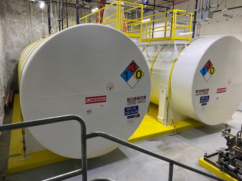
Optimizing Fuel Systems: A Proactive Approach to Multiple Main Tank Design for Performance and Safety
One common practice in fuel systems involves connecting multiple bulk storage tanks to increase the overall fuel capacity, often motivated by factors such as the maximum size tank that can be factory fabricated or constraints related to room dimensions and access ways. Although the reasons for adopting this configuration may vary, it presents challenges that need to be carefully assessed for both performance and safety considerations.
Historically, the prevalent approach to connecting multiple main tanks has been passive solutions. This typically involves using an "equalizing" line or connecting both tanks directly to the transfer pumps and piping them together before the pumpset inlet. While these options are commonly observed in the field, each comes with its own set of risks.
Firstly, maintaining a containment secondary wall with an equalizing line can be challenging unless intricate welding techniques are employed.
Secondly, many discover through experience that if one tank becomes empty, or nearly empty to the point where the fuel is below the drop tube, the system may draw air from the empty tank rather than pulling fuel from the other one.
The key to a well-designed system with multiple main tanks lies in active control rather than a passive setup. Each tank should be equipped with at least two control valves – one for supply and one for return. These valves should be capable of proving positions in both the open and closed states, making a motorized ball valve with end switches a recommended choice. This not only ensures optimal performance but also enhances safety. For instance, if the return valve is not in the open position, the relief valves on the transfer pumps may lack a path back to the tank. Incorporating tank level monitoring enables automatic switchover on low fuel levels.
To illustrate, consider the examples below, with the first depicting a passive system and the second showcasing an active one.


