Ignition System with Inductive Sender - Part 2
Here, at this second part the focus is on the wiring diagrams, entrance and exit clamps, as well as trigger box pin layout of an older generation of ignition systems with inductive sender according to different manufacturer application, such as: Ford, Peugeot, Mitsubishi and Mercedes.
This article is a continuation from the previous and it's recommended to take a look the first part at the following link: Ignition System with Inductive Sender - Part 1.
Different Types of Ignition Systems with Inductive Sender:

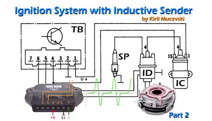
Figure 1) Ignition System with Inductive Sender at Ford Vehicles
Ignition trigger box (electronic control unit) terminal layout:
1) and 2) entrance from the inductive sender, 3) exit clamp: 1 ignition coil indicator, 4) entrance clamp: 15 battery+ through ignition switch, 5) entrance clamp: 31 (ground)
Ignition coil terminals:
Terminal 1: (ignition coil, distributor, low voltage) = negative ignition coil clamp,
Terminal 15: (battery+ through ignition switch) = positive ignition coil clamp.

Figure 2) Ignition System with Inductive Sender at Peugeot Vehicles
Ignition trigger box (electronic control unit) terminal layout:
1) exit clamp: 1 ignition coil indicator, 2) entrance clamp: 31 (ground),
3) entrance clamp: 15 battery+ through ignition switch,
4) and 5) entrance from the inductive sender.

Figure 3) Ignition System with Inductive Sender at Mitsubishi
Ignition trigger box (electronic control unit) terminal layout:
1) exit clamp: 1 ignition coil indicator,
2) entrance clamp: 15 battery+ through ignition switch,
3) and 4) entrance from the inductive sender, 5) entrance clamp: 31 (ground).

Figure 4) Ignition System with Inductive Sender at Mercedes Vehicles
Entrance clamp 15: battery+ through ignition switch,
RPM out: exit clamp for engine rpm,
16 (the same as 15a): from ballast (dropping) resistor to ignition coil and starter motor, 31: return to battery minus or direct to ground.
To learn more about the diagnostics and testing procedures of these ignition systems with inductive sender, please take a look my previous article at the following link: Ignition System with Inductive Sender - Part 1
- - - - - - - - - - - - - - - - - - - - - - - - - - - - - -
Thank you for reading my post! If you found this useful, please let me know - just click the like button or provide your comment below.
If you would like to read similar automotive articles, repair tips & tricks or testing procedures, you are welcome to visit my LinkedIn article page:
• OBD-II Connector and Fault Codes Explained
• Inductive and Hall Effect RPM Sensors Explained
• Engine Oil Pressure Switch Explained
• Fuel Injector Operating Principles and Diagnostics
• Automotive Relays Fundamentals and Testing
• Motor Vehicle Brake Fluid Fundamentals and Testing
• 6 Tips to Prepare Your Vehicle for Summer Driving
• What Do Dashboard Warning Lights Mean?
• Marking of Passenger Car Tires and Their Meaning
Designed and published by Kiril Mucevski
Automotive Engineer with more than 15 years experience in:
• Vehicle Diagnostics, Maintenance & Repair
• Roadside Assistance, Trainings for Vehicle Diagnostics & Breakdowns
• Building Race Engines, Engine Modification, Development & Testing
• Researches in the field of IC Engines, Propulsion Fuels, Motor Oils & Additives
• Sales of Tires & Alloy Wheels, Resolving Warranty Issues
• Writing and Publishing Automotive Technical Books, Manuals & Articles
Also, if you like to read my future posts, please click "Follow" or even better, send me a LinkedIn invitation, I'm glad to expand my network with new connections.
Automotive Engineer • Photographer • Content Creator
8yThanks for your feedback and interest to this article, Chris John. Also, you are welcome to visit my Linkedin article page and read my other related articles about ignition systems with Inductive and Hall effect sensors.
Automotive
8yGreat job
Automotive Engineer • Photographer • Content Creator
8yThank you Sime. It's nice that you found this article useful.
Race Engine Specialist | High Performance Race Engine Parts
8yVery useful article for diagnostics the older generation of ignition systems with inductive sensor. Nice schematics.