Good Practices for the Design of Condensate Recovery Systems, Part - 2
Introduction
The transport of steam condensate from the trap location to the condensate return header elevation is a complicated two-phase flow phenomenon. Because of the layout of condensate collection networks in the oil and gas industry where both steam and condensate headers are on the pipe racks while most consumers are at lower elevation, the transport of liquid in the condensate recovery systems is predominantly happening in the slug/plug flow regime. Even in cases where the gas and liquid flow in two distinctive (separate) layers such as stratified or annular regimes in a horizontal pipe, they form slug/plug flow regime in the vertical lines. The liquid is gradually collected in the trap discharge line until the velocity of steam (either flash steam, live steam, or a mix of both) is high enough to push a plug of liquid from the ground to the elevated return header. This is especially the governing mechanism for the traps in intermittent services like heat tracing where the traps opening drains a limited amount of condensate to the discharge line.
The condensate in the shape of liquid piston is carried upward by the high velocity steam before being delivered to the condensate header. In this condition, significant wave can be formed along the horizontal run by high velocity steam moving over the surface of the liquid. When a wave grows large enough, it momentarily seals the cross section of the horizontal pipe, building a pressure wall behind it. This causes a water slug to accelerate in the line, potentially causing serious damage to piping, valves, gaskets or fittings. Although this transient behavior of system is not favorable from the mechanical perspectives, it is effectively the main method of moving liquid in the condensate system.
This paper covers the pipe routing requirements to facilitate the condensate transfer from the steam traps to the condensate flash drum.
Minimize the length of horizontal run at the discharge of steam trap
As mentioned above, the condensate slug/plug is transported by high velocity steam to the header elevation as soon as it fills the steam trap discharge line/sub-header to the level that is enough for gas to attain the velocity required to lift the liquid. The size of liquid plug is directly related to the length of low point piping before the riser. The longer the pipe, the larger the liquid piston, which means higher momentary backpressure during the lift.
Therefore, it is good practice to ensure the horizontal discharge line is not excessively long and the pipe turns vertical as soon as practically possible.
Avoid horizontal run in the condensate riser
When the pipe orientation changes from vertical to horizontal, there is a high chance that the flow regime changes from the slug to stratified. As shown in figure below (which has been produced by superimposing the flow regime maps for vertical and horizontal lines), almost always the slug/plug flow regime in a vertical pipe (pink area) becomes stratified in the horizontal line (shown with thick boundary lines). Every time this happens, the liquid piston may break causing liquid to slide back to the trap location, which will hit the trap causing mechanical damage and may also collide with the newly discharged condensate resulting in a water hammer.

Moreover, this increases the amount of liquid on the horizontal run of pipe downstream of trap leading to a larger liquid leg and longer liquid piston in the riser which will create higher backpressure on the trap for condensate to reach the elevated return header. The order of magnitude of the intermittent pressure to move the liquid plug depends on the elevation difference and size of liquid column and can be estimated based on the effect of velocity change in the surge calculations. Additionally, there will be some acceleration losses causing higher backpressure on the upstream traps.
To avoid these problems or at least to minimize the reoccurrence of pressure wave, the common piping design practice is to have a single riser from the steam trap to the condensate return header elevation and connections to the top of main condensate header.
If it is not possible to meet this requirement, the arrangement shown in the following figure is proposed. This alternative design is usually used to collect condensates from a section of plant where the elevation of top tier of pipe rack is lower than the elevation of main condensate header. In this arrangement, the transfer of condensate takes place in two steps, first from the trap discharge line to the unit sub-header, and then from sub-header to the main header. The connection to the top of the unit sub-header prevents the reverse flow of liquid to the traps. Dead ends are avoided in this configuration and it is preferred to connect a continuous condensate producer (if exists) to the end of unit sub-header to sweep the liquid from the sub-header more frequently.

Provide check valve at the outlet of steam trap with rising sub-header
Considering the risk of condensate backflow in the trap discharge line when the sub-header is rising to the condensate main header elevation, it is recommended to provide a check valve at the bottom of riser.
In the absence of check valve, every time the liquid piston fails to reach the condensate return header, it falls back in the riser and hits the steam trap. This is the main reason for the failure of steam traps in the flooded systems besides other problems.
Provide free draining in the condensate return header
The condensate collection header should be free draining towards the condensate flash drum to ensure that the liquid sits at the bottom of pipe and flows to the destination drum by gravity where steam occupies the top section of pipe. This does not necessarily guarantee that the system will operate outside the slug/plug flow region, but it minimizes the likelihood of these flow regimes and subsequently its detrimental consequences such as high pressure drop, slugging, water and steam hammering and associated mechanical damages.
The condensate return headers with low and high point (vertical loops) are prone to creating severe shocks from the acceleration of slugs within the piping. Moreover, when the flash steam flows into a return header that contains sub-cooled condensate at a much lower temperature in the low point pockets, an instant collapse (condensing) of the steam will occur as it gives off its latent heat to the condensate, leading to the steam hammer.
In a real example, the condensate header from the plant offsite (OSBL) area with the total length of more than 200m was routed through several culverts (as shown in figure) before reaching the condensate flash drum in the utility section which made the transfer of liquid condensate nearly impossible.

When the condensate-steam mixture is continually or very frequently discharged to the main return header, the static pressure of the vertical riser is corresponding to the mixed steam-condensate density multiplied by the vertical leg height. If the condensate is stored in the long discharge line for a long time, the condensate will be gradually cooled (despite being thermally insulated) and degassed, causing the mixture density to increase. The density of degassed condensate can be up to 4 times higher than the mixture density which substantially increases the pressure required to lift the liquid to the main header elevation. With a poor piping arrangement (such as above example), this phenomenon can happen in the winter when the ambient temperature is very low and also in summer when the condensate flow rate is low because of low tracing heat load.
In above example, there is more than 11m lift at the ISBL battery limits for the OSBL condensate to reach the main header. This can substantially affect the ability of steam traps in the OSBL area to push the condensate into the condensate recovery system. For cases where the proper piping layout for the condensate return system is not possible, installing a local flash vessel and pumping the condensate to ISBL, using pumping traps or employing other types of heat tracing such as electrical tracing may be more appropriate.
Provide check valve close to the main header for falling sub-header
When steam traps are gravity draining to the main condensate return header, the steam from the top of the header can backflow into the condensate discharge line. Mixing of high temperature steam with low temperature condensate in the discharge line can cause steam to collapse creating a shock wave and knocking sound that can be heard from distance. This type of hammer can be resolved by installing a check valve at the entry point of discharge line to the condensate return header- thereby preventing the reverse flow of steam. The check valve in this application must be spring type (not swing) so that it closes as soon as forward flow stops.
Limit the steam tracers’ length and depth of pocket
For steam tracing applications, the condensate is formed in the tracer line itself and flows along with the steam. Because the routing of steam tracers is dictated by the process pipe routing or equipment shape and dimensions, it is not always possible to have free draining design for the liquid to flow by gravity to the trap. This means that in order for steam to push the condensate through the tracer line, there are some limitations on the total length of tracer and the total elevation difference between the bottom and top of the tracer line (i.e. pocket depth) as shown in figure below:

Summary
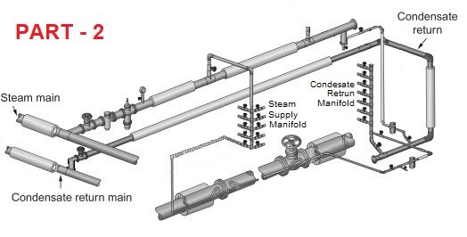
The following sketch depicts most of piping layout requirements explained above:

About the Author
Saeid Rahimi Mofrad is a principal process consultant with a proven track record in the hydrocarbon industry and a wide experience on the equipment sizing and selection and flare system design. He has prepared many sizing procedures and more than 180 spreadsheets for different process calculations. He has also published and presented more than 50 papers in different international magazines, websites, and seminars and conducted many training courses and workshops for his employers as well as third parties.
Mr. Rahimi is the founder of Chemwork discussion forum on LinkedIn (http://www.linkedin.com/groups/Chemwork-3822450) and has also developed a professional process engineering software called Chemwork for oil and gas processing equipment sizing and design calculations in a very user-friendly environment. Software demos are available on YouTube (https://youtube.com/user/Chemwork).
He can be reached at s.rahimi@enernik.com
2013.01 - Present : SK Engineering & Construction Co.
5moSo far, we have formed SUBHEADER height higher than MAIN HEADER and applied SUBHEADER to SLOPE. Is there no problem even if SUBHEADER is lower than MAIN HEADER as shown in the picture above?
Senior Process engineer
6moGreat article, this is the information what I need for checking condensate return line, thanks!
Senior Process Engineer
2yInteresting
Lead C&I Engineer
2ySaeid .. Excellent article... Thanks..