
Kimball Physics specializes in the design and manufacturing of precision high-tech scientific instruments with over 50 years of experience in ultra-high-vacuum electron and ion optics. Our expertise is in high stability electron emitters, precision electrostatic and magnetostatic optics, along with state of the art vacuum chambers and fittings.
Kimball Physics emitters provide a reliable source of electrons or ions for use in a variety of instruments including scanning and transmission electron microscopy, electron lithography, x-ray generation, free electron lasers, electron accelerators, and other custom applications. Other applications include our own Kimball Physics electron and ion sources / guns.
Our goal with this informal resource is to provide a fundamental knowledge base for understanding the basic terminology, principles and parameters of cathodes /electron emitter systems to enable you to select the ideal electron emitter for your application.
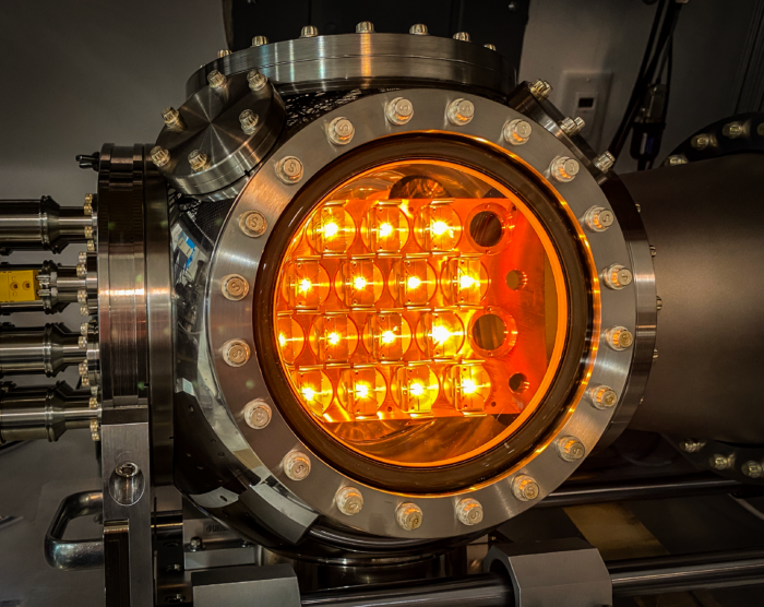
Figure 1. Cathode Test Chamber with several cathodes being “run up to temperature” and tested prior to delivery.
There are three basic mechanisms of electron emission used either alone or in combination: 1) thermionic emission, 2) photo-emission and 3) field emission. Kimball Physics’ cathodes are predominately based on thermionic emission and this will be the focus of this document.
Thermionic emission is generally described as the discharge of charged particles (usually electrons) from an electrode (cathode) at high temperature, and typically in a vacuum environment. At elevated temperatures, a significant portion of the electrons exceed the energy required (work function) to escape from the material.
One of the simplest and most classic configurations that could serve as a source of electrons is from a refractory metallic wire or filament, such as tungsten, that is bent into a hairpin shape. When a small voltage is applied across the wire to pass a current through the wire’s resistance, heat is generated to create high temperatures. If the material has a high enough melting point, enough energy will be present in the material to liberate the electrons.
Electrodes (i.e. cathodes and anodes) are simply conductors with geometries that interface with non-conductors in the system (such as the partial vacuum space). They are typically used to either establish a point of current entry or exit in the system or as a datum of voltage potential to create electric field gradients. In addition to the cathode, the anode (second gird or plate) and Wehnelt (grid or first grid) are typical electrodes present in electron source /emitter systems.
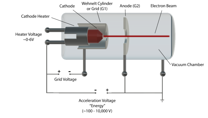
Figure 2. Schematic of cathode, Wehnelt(grid) and anode in basic electron gun (triode).
The Wehnelt is typically in a bell-shaped geometry and the anode a more circular flat washer-like structure, both with a central aperture (see Figure 2). The Wehnelt is in close proximity to the cathode with its aperture plane similar in height to the cathode emission surface. It is often slightly more negative in potential than the cathode and is often used to create a repulsive electric field to focus and also suppress electron emission. The anode is usually positioned at a small distance from the cathode and concentric to the perpendicular axis from the emission surface, with typically a large potential difference between the cathode and anode structures, often thousands of volts, with the intention of accelerating the electrons away from the cathode’s emission surface and initially aggregating and focusing them into a beam configuration that passes through the central anode aperture. Most electron sources /guns will have additional structures to create multiple additional electric or magnetic fields along the beam path to serve as “electron optics” to focus, shape and shift the beam trajectory.
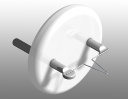
Figure 3. Tungsten Hairpin Cathode mounted on AEI base.
The extraction field, which is the summation of the combined electric fields between the cathode and the adjacent first anode and the Wehnelt grid can then be modulated is several ways to 1) accelerate and focus the electrons from the cathode surface to create and begin to organize the electrons into a structured beam or 2) partially or fully suppress electron emission from the cathode surface.
The energy to liberate the electron, also known as the work function, is the amount of energy (eV) the electron needs to “evaporate or boil” out of the heated material(emitter) into the vacuum space adjacent to the surface. Materials with low work functions can emit electrons at lower temperatures. However, even low work function materials need to be heated to well over a thousand of degrees Kelvin (1100 – 2350oK) for thermionic emission. The electrons emitted from the material are typically “back filled” by a small fraction of the source current used to heat the cathode.
The heating current does not need to pass through the cathode directly to heat the emitter. An alternative and more stable approach, used in Kimball Physics’ novel technology, is to indirectly heat the cathode material by thermal conduction from the surrounding support material. For example, in our ES423 Lanthanum Hexaboride (LaB6) cathodes, this support structure is made of carbon, and allows for more uniform and long-term stable heating of the LaB6 crystal structure.
If there is an excess of electrons (space charge) adjacent to the emission surface, the emission electrons will be more likely to return to the material. The space charge is related to the electric field that results from the presence of several charged particles (electrons) in a region of space that can limit the emission of either more electrons from a cathode or can affect the path of charged particles through a region.
The actual electron emission (emission current) from the cathode is a function of many factors, and most notably the cathode’s temperature,
the properties of the electric field created between the cathode and the first anode and Wehnelt grid, and the cathode’s material properties.
When cathode temperatures are relatively low and first anode voltage (and subsequent electric field) is relatively high, the cathode is operating in a temperature limited mode. In this mode, emission from the cathode is limited by the temperature of the material and not by the ability of the electric field to move charges away from the surface to limit the space charging effect. There is an exponential relationship between the electron emission and the cathode temperature that can be described by the Richardson-Dushman equation:
J = AT2e–f/kT
Where:
J = emission current density in amps/cm2
A = Richardson’s constant
T= cathode temperature in degrees Kelvin (K)
f = work function of cathode material in eV
k = Boltzmann’s constant (8.6 x 10⁻⁵ eV/K)
At higher cathode temperatures and lower first anode voltages, the cathode is operating in a space charge limited mode, with a relationship between electron emission and first anode that predominates.
This space charge limited mode can be described by the Langmuir-Child space charge equation:
J = K V3/2 / d2
Where:
J = emission current density in amps / cm2
K= constant based permittivity of free space and the charge mass ratio of an electron, where K ~ 2.335 x 10⁻⁶
V = cathode – anode voltage difference in volts
d = distance between cathode and anode in cm
If first anode potential is fixed at a relatively low level and cathode temperature is increased, the cathode’s emission characteristic makes a transition from a temperature limited relationship to a space charge limited relationship. This is illustrated in the figure below where first anode voltage is held constant while the cathode temperature is increased by increasing source voltage.
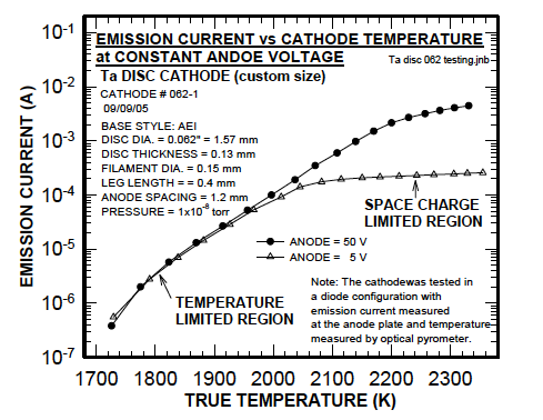
Figure 4. Effect of Temperature on Cathode Emission at a Constant Energy (data from a typical cathode)
At lower temperatures, the Richardson-Dushman equation applies and electron emission increases with increasing temperature until a space charge limited temperature region is obtained. In this space charged limited region, the emission begins to level off even as the cathode temperature continues to increase. The first anode field strength is not sufficient to extract all the available electrons at these higher temperatures.
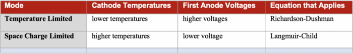
Table 1. Summary of Emission Modes
If cathode temperature is fixed and first anode voltage is increased, the cathode’s emission characteristic makes a transition from a space charge limited relationship to a temperature limited relationship. This is illustrated in figure below where cathode temperature is held constant by fixing the source voltage, while the first anode field is increased. At lower first anode voltages, an increase in first anode produces an increase in emission according to the Langmuir-Child relationship.
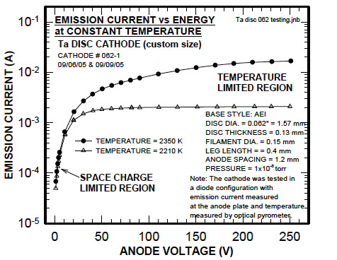
Figure 5. Effect of Energy Voltage on Cathode Emission at a Constant Cathode Temperature (data from a typical cathode)
Emission levels off at higher first anode voltages because the cathode’s temperature is too low to produce additional electrons.
Operating the cathode in a temperature limited mode results in beam current drift as the cathode temperature drifts. Operating the cathode in upper space charge limited region results in shorter cathode lifetimes since the cathode temperature is excessive.
The cathode lifetime decreases with increasing cathode temperature because the cathode material evaporates away more quickly at higher temperatures. The degree of evaporation is a function of the vapor pressure intrinsic to the material. To balance the need for beam stability, adequate emission, and maximum cathode lifetime, the cathode should be operated in the transition region between temperature and space charge limited modes.
The cathode is a low power device and is driven by a voltage source rather than a current source. However, monitoring of source current can be more useful than the monitoring of source voltage because small variations in source current are easier to observe and source current is not dependent on variable voltage drops, such as occurs across different cable lengths.
The quality of the vacuum around the cathode also strongly affects the functional lifetime of the cathode. Certain material are more tolerant of poor vacuums than others. For example Ytrium and Tantalum material cathodes can tolerate vacuum in the range of 10-4 and 10-5 torr respectively, whereas Lanthanum Hexaboride performs better at lower pressures, in the range of 10-7 to 10-8 torr. In their optimal vacuum environments, these cathodes routinely provide several thousand hours of operation. Contaminant or chemical poisoning in poor vacuum, such as oxygen, water, carbon and nitrogen can also affect the quality of emission from the cathode surface.
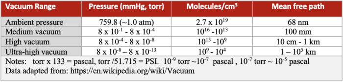
Table 2. Examples of vacuum ranges and values.
Typical vacuum ranges and other parameters are provided in the Table 2 for reference. Recommended vacuum ranges for Kimball Physics’ various cathodes are provide in the Cathode Summary Table.
Where the electron goes once emitted largely depends on its energy and the electrical fields in the space around the cathode. If the electron does not have enough energy, or if the space around it has too much negative charge (space-charge limited), the electron will return to the cathode. The electrons that do leave the cathode can be accelerated and aggregated into an electron beam.
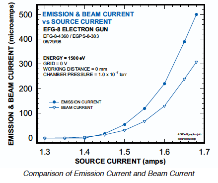
Figure 6. Example of the differences in emission and beam currents vs. source current (related to cathode temperature) in an example system.
The emission current is defined as all the electron current that leaves the cathode and eventually goes to ground. This emission current predominately depends on 1) the cathode temperature, 2) the primary electric field between the cathode and anode and 3) the electric field created between the Wehnelt (grid) and the cathode. However, not all the electrons emitted from the cathode will be found the electron beam (beam current).
Some of the electrons may land on other elements in the electron gun column and return to ground, but not through the electron beam. Thus, the final electron beam current at the target will be consistently less than the initial emission current (see figure above).
As shown in electron gun example figure below, increasing first anode voltage increases the emission current, and thus increases the final beam current for a given set of operating parameters. This effect levels off at higher anode values, reflecting the change from a space charge limited situation to a temperature limited one.
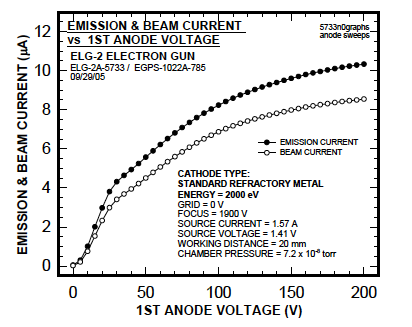
Figure 7. The effect of the 1st Anode Voltage on Emission Current from the cathode and the final Beam current.
The Wehnelt or grid voltage (G-1) will also affect the beam current. Increasing the Wehnelt potential makes the Wehnelt aperture more negative with respect to the cathode. As the Wehnelt potential increases (becomes more negative, also known as increasing the grid bias), the electric field between the cathode and Wehnelt suppresses electron emission, initially from the cathode perimeter, leaving only the center of the cathode to emit electrons. If enough Wehnelt potential is applied, the beam emission will be completely suppressed, and the beam is said to be cut off.
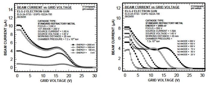
Figure 8. The effect of Grid Voltage on final Beam Current, showing cutoff at different Energy levels on the left, and showing cutoff at different 1st Anode voltages on the right.
This cut-off effect of increasing grid voltage is illustrated in the figures above at different Energy levels. Although Energy level affects the amount of beam current, it does not affect the cut-off point on this example system. The figure also shows the effect of different first anode (G-2) levels on beam suppression by the Wehnelt grid (G-1); the grid cutoff value is an increasing function of anode voltage.
The electric field created by the Wehnelt also controls beam divergence and uniformity by varying electron trajectory. Grid cut-off voltage can also be used to pulse the electron beam off and on.
The spot size is the diameter of the electron/ion beam at a given distance from the electron gun (working distance). This working distance may range from a few microns to several hundred millimeters, depending on the gun design. Generally, the smaller the spot required for the application, the smaller the needed emission surface dimension.
Brightness or source brightness is the electron current density or number of electrons per unit area or (spherical sector). Some cathode materials have higher brightness than others, for example single crystal LaB6 cathodes are high brightness sources. High brightness applications (which require small spot size for improved resolution) include scanning electron microscopes, transmission microscopes, electron probes, scanning Auger systems and electron lithography systems. Brightness is directly related to beam current density.
With single crystal emitters such as Kimball Physics LaB6 cathodes, the orientation of the emitter’s crystal lattice can affect the work function and subsequent emission from the crystal surface. From one study using LaB6 crystals [Liu, 2017], the work function was measured in the (100) (110), (111), (210), and (310) planes to be 2.66 eV, 2.73 eV, 2.78 eV 2.69 eV, 2.72 eV, 2.71 eV respectively. For high brightness applications, such as scanning electron microscopy, the LaB6 (100) plane has been found most favorable for 1) brightness, 2) emission symmetry about the optical axis, and 3) emission consistency as the cathode evaporates over its’ lifetime.
Crystal based cathode components are commonly first fabricated into a cylindrical geometry, with the long axis of the cylinder perpendicular to the intended crystal plane for electron emission. During fabrication of the emitter, one end of the cylinder will remain intact and will be used to mount the crystal in a support or heating structure. The other end of the cylinder will be formed into a conical shape, with the apex of the cone concentric with the long axis of the cylinder. The angle between the conical faces in a plane that passes through the long axis of the cylinder determines the cone angle. Typical angles found in Kimball Physics cathodes include 60 and 90 degrees, however, one version of the product has a cone angle of 180o, and thus is a planar configuration where the microflat is the diameter of the cylinder.
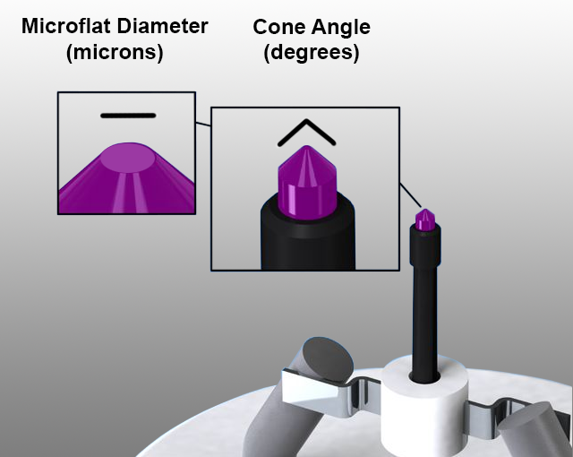
Figure 9. Microflat and conical geometry references used with LaB6 crystal emitters.
Typically the apex of the cone is then truncated to create a circular microflat region. This microflat is formed on the optimal crystal plane for the electron emission (i.e. (100) for LaB6). Generally, the smaller the dimension of the microflat, the smaller the potential spot size of the electron beam. With the ability to more uniformly heat this localized region, the energy spread (see below) can be minimized to create a more uniform beam energy profile. The orientation of the lateral conical surface is not in the crystal’s optimal orientation, and therefore will generally have a higher work function with less electron emission occurring from this surface. Typically, a 90 degree cone is used in most SEM and TEM applications. A 60 degree cone is often used for high resolution TEM.
Methods are available to shield the conical surface and just expose the microflat to promote emission of electrons predominately from the microflat surface. This approach is used in Kimball Physics’ Guard Ring Cathodes (ES-423GR). This allows a smaller and more uniform energy profile of emission electrons.
The energy spread is the energy width or distribution of an electron beam. This is related to variation in the initial speed of the electrons emitted from the cathode and by inelastic scattering of electrons in a specimen.
Heating current is either 1) directly passed through the emitter structure or 2) applied to a secondary heating structure adjacent to the emitter that provides heat by conduction or radiation. This heater current is typically provided by an external power supply. Although voltage is the parameter that is most commonly controlled using most power supplies, it is the actual current flow through the structure would be a more accurate way to ultimately determine and control the ultimate cathode temperature. If current flow can be measured, it is easier to control the temperature and subsequent emission current from the cathode. Typical electrical parameters are in the range of a voltage potential difference (~ 3-4 volts) across its resistance (~1-3 ohms) , with a “source” current (~1.5 – 3A).
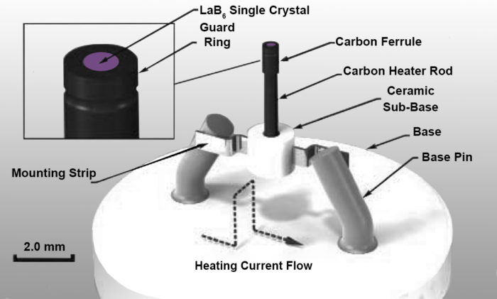
Figure 10. Guard Ring (GR) LaB6 configuration on AEI base.
The emission current passing through a specified emitter surface area is related to the emission current density often referred to as cathode loading with units of amps per centimeter squared (A/cm2). The cathode loading is related predominately to the emitter material and values of 0.25 A/cm2, 0.1 A/cm2, 0.5 A/cm2, 1.0 A/cm2 and 30 A/cm2 for Tantalum(Ta), Barium Oxide(BaO), Yttrium Oxide(Y2O3), Tungsten(W) and Lanthanum Hexaboride (LaB6.) respectively. LaB6 has a cathode loading and subsequent brightness nearly 10x greater than Tungsten. For high brightness applications, higher cathode loading capability is advantageous.
The design configuration of the cathode is related to the requirements for beam current, intended spot size and brightness. There are basically two design categories: 1) planar and/or disc emission surfaces or 2) conical single crystal geometries with truncated apices at various levels to obtain intended microflat dimensions.
For high emission and beam current applications with larger intended spot sizes such as lithography, electron-beam welding and x-ray sources, large planer crystal face configurations of LaB6 crystal can be used. Other disc designs with a refractory material surface (Ta) or coated refractory metal surface (BaO, Y2O3) are also available to provide a broad range of functionality.
For high brightness, small spot size applications such as electron microscopy and surface analysis, the cathode tip is designed to provide a small emitter surface (microflat) that can deliver high emission current densities. As previously discussed, these designs typically use material such as LaB6 that have a conical infrastructure, whereby the cone apex is truncated at various levels to create the intended circular microflat dimension in the optimal crystal plane orientation for the application( usually the (100) crystal plane). The cone angle is typically either 60 or 90 degrees, whereby a 90 degree cone angle with a 15 micron microflat functions is common for most scanning (SEM) and transmission (TEM) electron applications with longer lifetimes and easier alignment. For higher resolution TEM applications, the 60 degree cone angle with very small microflats (6 microns) is typically used for higher brightness.
In the section that follows, we provide an overview of the various cathode types available from Kimball Physics.
Cathode types for thermionic electron emission available at Kimball Physics include:
-Lanthanum Hexaboride (LaB6)single-crystal
-Tantalum (Ta) Disc
-Barium Oxide (BaO) coated Disc
-Yttria (Y2O3) coated iridium Disc
At the end of the section, we provide a summary table of various parameters for each cathode material. . The reader is also encouraged to also access the PDF documents referenced at the end of this document for more detailed discussion and information.
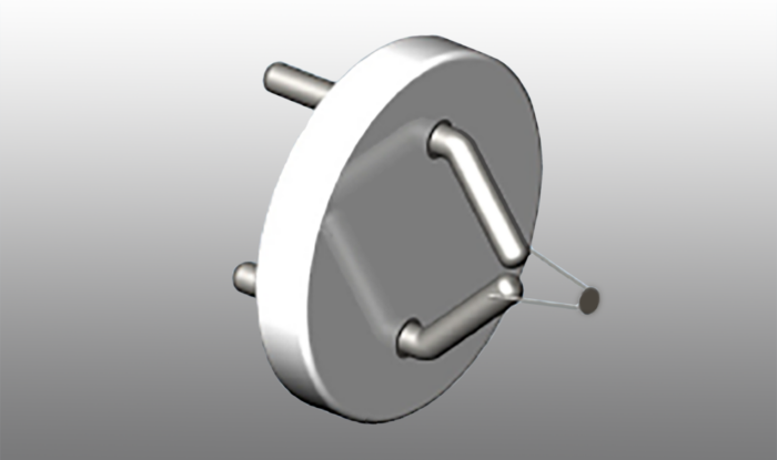
Figure 12. Tantalum (Ta) Disc Cathode on AEI base.
Tantalum is a refractory metal thermionic emitter consisting of a tantalum disc mounted on a tungsten 3% rhenium hairpin filament wire. The cathode is quite sturdy and provides stable and uniform electron emission. The disc provides a circular, planar emission surface that emits electrons when the filament wire is heated by the voltage source. The disc is welded to the filament at a single point, resulting in a unipotential and planar surface emission. Since no heating current passes through the tantalum disc, the energy spread (<0.7 eV) is kept to minimum. Tantalum has a very low vapor pressure at high temperatures, and a high melting point (3188 K). Tantalum has a work function of 4.1 eV, with an energy spread of about 0.6 eV, a typical operating temperature of 2200 K, with recommended cathode loading of 0.25 A/cm2 and vacuum levels of 10-5 torr or better.
The cathode is not harmed by repeated exposure to atmosphere when cold; however, at temperatures above 700 K, oxidation of both the tantalum and tungsten takes place in the presence of water vapor, air or oxygen with a resulting decrease in cathode lifetime. At temperatures above 1200 K, tantalum nitrides form in the presence of nitrogen; these compounds degrade the emitting characteristics of the tantalum disc.
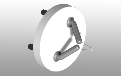
Figure 13. Barium Oxide (BaO)) Disc Cathode on AEI base.
The Barium oxide (BaO) disc cathode is a low-light, lower temperature emitter with good stability. The cathode structure consists of a barium oxide (BaO) coated disc substrate that is heated by conduction from a tungsten hairpin filament.
The BaO cathode has a lower cathode heating current range and a lower operating temperature than a standard, un-coated, refractory metal cathodes (related to its lower work function). With the lower temperatures, there is less light emitted which is an advantage in situations where light could interfere with viewing the target. The BaO cathode gives a smaller energy spread than a standard cathode, and has a longer lifetime due to the lower heating current. However, the BaO coating is susceptible to degradation from water vapor, so it is recommended that the barium oxide (BaO) cathode be operated in a vacuum of 10-7 torr or better. In addition, the cathode should be stored in vacuum or in a dry environment. Exposure to moisture in the air allows the oxide to form hydrates, which can cause flaking of the barium oxide.
Barium oxide (BaO) has a low work function of 1.0 – 1.8 eV, with an energy spread of 0.3 eV, a typical operating temperature of 1150 K, with recommended cathode loading of 0.1 A/cm2 and vacuum conditions better than 10-7 torr.
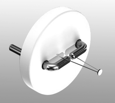
Figure 14. Yttrium Oxide (Yttria) coated Iridium Disc Cathode on AEI base.
The Yttrium Oxide (Yttria) coated Iridium disc cathode is a rugged thermionic emitter that resists oxidation and can provide stable and uniform electron emission. The hairpin heating structure can be composed of either iridium or tungsten. Yttria has a lower work function than the uncoated refractory metals, so more electrons will be emitted at a given temperature, or a given electron emission can be achieved at a lower temperature.
Iridium, a noble metal, is more resistant to oxidation and other forms of chemical attack than the refractory metals. Thus, the cathode will not easily burn out if accidentally exposed to atmosphere while running. It can be used at operating temperature in poorer vacuum conditions. The Yttria -coated iridium cathode with iridium hairpin can be operated in a vacuum of 10-4 torr although 10-5 torr is recommended for the similar cathode with the tungsten hairpin heater. The cathodes are not damaged by repeated exposure to atmospheric gases or water vapor when cold. The yttria- coated cathode does not require any special care other than protection from mechanical shock which could physically remove the coating.
As the cathode is heated, the Yttrium Oxide near the surface of the coating dissociates, and the positive Yttria ion migrates to the surface, while the more negative oxygen remains in place; this acts as a dipole accelerating electrons near the surface, which further decreases the work function.
Yttria has a work function of about 2.6 eV, with an energy spread of 0.6 eV, a typical operating temperature of 1800 K, with recommended cathode loading of 0.5 A/cm2 and vacuum conditions 10-4 or 10-5 or better depending on which hairpin material is used.
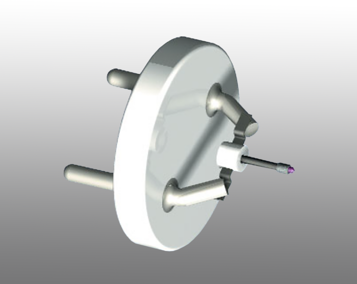
Figure 15. Lanthanum Hexaboride (LaB6) single crystal cathode on AEI base.
The Lanthanum Hexaboride cathode is a high performance, resistively heated, thermionic electron source. It is currently employed in many brightness-limited electron optical systems: SEM’s, TEM’s, probes, electron lithography systems, etc. Several models /variations of this cathode are available.
The LaB6 (100) oriented single crystal is typical mounted on the end of a single-piece of stress-free carbon heater rod, and is held in place by a carbon ferrule. The carbon rod is precision machined with a 100 µm slot cut along the axis, such that the heating current goes up one side and down the other. The small area of the heating current loop keeps the unwanted heater current’s magnetic field low. Because the rod is one single piece, no significant heating current passes through the crystal; there are no high temperature current-carrying joints. The design is such that the crystal could be completely evaporated away without affecting the heating circuit. A high degree of axial symmetry keeps mechanical motions small.
Lifetimes up to 3000 to 4000 hours may be achieved at operating temperatures of 1850 K (corresponding to material surface loss rates in the range of 0.025 micron/hour), with full brightness and excellent stability.
The work function of LaB6 is 2.69 eV, with an energy spread of approximately 0.4 eV, with a typical operating temperatures of 1700- 1900 K with a recommended cathode loading of 20-30 A/cm2 and vacuum conditions better than 10-7 torr. The lower work function of LaB6 yields higher emission currents at lower temperatures for high brightness applications, with the lower temperatures enabling a reduced rate of evaporation to allow extended lifetimes.
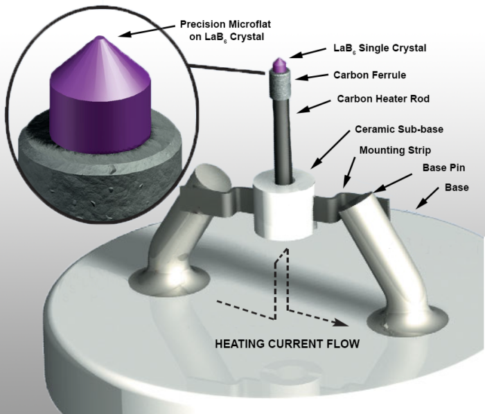
Figure 16. Base components typically found LaB6 single crystal cathode.
In our LaB6 cathodes, the very tight tolerances and the enclosed structure prevent the loss of LaB6 in the mounting region throughout the entire crystal life. Reduced material loss also means less Wehnelt contamination. A high angular tolerance is maintained on the perpendicularity of the oriented single-crystal emission plane to the electron optical axis.
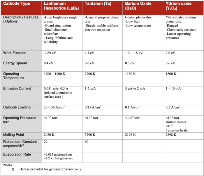
Table 3. Cathode Summary Table
The cathode base is the interface between the instrument and the cathode emitter and enables 1) precise and stabilize attachment of the cathode emitter to the system 2) proper alignment of the emitter in the center of the base and the instrument, 3) position of the emitter surface at a specified distance from the base surface, and 4) electrical connection for heating current and providing a voltage potential datum. Other important factors include symmetry and thermal expansion matching as the cathode is elevated in temperature.
Cathodes bases at Kimball Physics are precision manufactured with high quality materials to high tolerances. Each cathode is individually inspected, accurately aligned and run up to temperature. All cathodes are shipped vacuum clean in secure, cathode transport containers and are ready to install.
Kimball Physics’ Cathodes are also available on several base configurations to interface with multiple instrumentation commercial systems:
-Standard ceramic AEI base
-Compact Kimball Physics CB-104 base
-Compact Kimball Physics CB-105 base
-Various commercial microscope bases
-Cathodes may also be mounted on customer-supplied bases
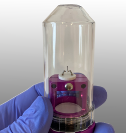
Figure 17. Cathode secured to base in transport container for safe storage and shipping.
All Kimball Physics cathode models are available mounted on the industry-standard ceramic AEI bases. Additionally many of our refractory disc models are available on Kimball Physics ceramic bases (CB-104 or CB-105), as well as on custom or non-standard bases. For electron microscopy and other analytical instruments that use electron sources, Kimball Physics provides a wide array of bases to support these instruments, predominately with our LaB6 cathode emitters.
AEI bases are the industry standard, typically with a 12 mm diameter ceramic base, with two plug in pins that are spaced 6.45 mm apart and are 1.0 mm in diameter. The ceramic base is typically 2.01 mm in thickness. The cathode emission surface is typically centered on the base at positioned at a specified height above the base surface. AEI bases ground to a tighter tolerance (12 mm +0.2 mm, -0.0 mm) are available for special applications. A high angular tolerance is maintained on the perpendicularity of the oriented single-crystal emission plane to the electron optical axis.
The compact Kimball Physics CB-104 and CB-105 bases are available in 2 and 4 pin configurations, with base diameters of 3.81 mm with pin diameters of 0.69 mm. These stable and compact design are primarily used in Kimball Physics Electron Gun /Source systems.
For Electron microscopy and other instrumentation bases, please refer to additional Kimball Physics documentation for cathodes types and bases available for these applications.
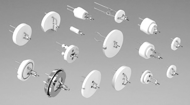
Figure 18. Kimball Physics cathodes are available on a wide variety of instrument bases.
Custom cathodes are available with LaB6 emitters in various conical and microflat configurations, or various refractory metals with various emitter styles (disc, hairpin, or ribbon), disc sizes, and filament lengths and diameters available.
Base options include two or four pins, with pins made of molybdenum or Kovar (with it favorable thermal expansion properties), various pin lengths and positions, as well as different mounting heights of the cathode emitter surface from the ceramic base can be fabricated.
We hope the information supplied has been helpful in expanding your knowledge of cathode emitters and providing better understanding of the capabilities of Kimball Physics’ products. We encourage you to review additional PDF product resources on the website for further detail and specific information about electron emitters and Kimball Physics Products. Please reach out to us with any questions and further suggestions for this document, Kimball Physics cathode options or to talk further about options that may be available for your custom application.