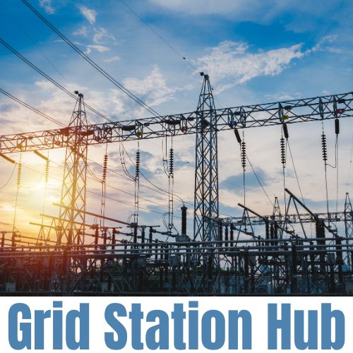

In an electrical grid station, the busbar scheme plays an important role in facilitating the transmission and distribution of electrical power. A busbar is a metal strip or conductor used to carry and distribute electrical current within a station. It provides a common connection point for various components, such as generators, transformers, and switchgear, enabling efficient power flow and control. Different busbar schemes are used based on the specific requirements of the grid station.

1- Single Bus Single Breaker Scheme:
A single bus single breaker scheme is a basic configuration used in small-scale grid stations. In this scheme, all electrical components are connected to a single busbar, forming a single point of supply. The busbar is equipped with a single breaker that provides protection and controls the flow of electricity. This scheme is relatively simple and low-cost, making it suitable for small installations with limited loads. However, it lacks redundancy and fault tolerance. If there is a fault in the system, such as a short circuit or equipment failure, the entire grid station may experience a power outage, disrupting the power supply.

Read More: The Role of High Voltage Circuit Breakers in Grid Stations
2- Double Bus Bar Single Breaker Scheme:The double bus bar single breaker scheme is an optimized configuration designed to improve reliability and fault tolerance. In this scheme, two parallel bus bars, known as the main bus and transfer bus, are employed. All electrical components are connected to both bus bars, which create redundant paths for power flow. The scheme includes a single breaker connected between the main bus and the transfer bus, allowing smooth switching between the two bus bars in the event of a fault or maintenance activity. If a fault occurs on the main bus, the breaker isolates it, and the transfer bus takes over the power supply, ensuring uninterrupted operation. This scheme has better reliability and fault tolerance than the single bus single breaker scheme.

3- Double Bus Bar Double Breaker Scheme:
The double bus bar double breaker scheme is a more advanced configuration used in medium to large-scale grid stations. It offers increased reliability, flexibility, and ease of maintenance. In this scheme, two parallel bus bars, bus A and bus B, are employed, and each bus bar is equipped with its breaker. All electrical components are connected to both bus bars. This scheme allows independent operation of each busbar and provides isolation and maintenance capability on a single busbar without interrupting the power supply. The double-breaker configuration ensures that each busbar has its own backup breaker, further improving reliability and fault tolerance. If a fault occurs on one busbar, the breaker isolates it while the other busbar supplies power.

4- One-and-a-half circuit breaker scheme:
The one-and-a-half circuit breaker scheme is a complex configuration widely used in grid stations that require a high degree of reliability. This provides better fault tolerance and ease of maintenance. In this scheme, there are two main busbars, A and B, and an auxiliary busbar C. Each busbar has its own breaker. All electrical components are connected to the main bus bars, while the auxiliary bus bar acts as a backup source. This scheme allows the isolation of faulty parts while maintaining the power supply to the rest of the system. If a fault occurs on bus A or bus B, the respective breaker isolates the faulty bus bar, and the system continues to operate using the auxiliary bus bar. This scheme offers a high level of redundancy and ensures an uninterrupted power supply even in case of breakdown or maintenance.

Conclusion:
The busbar scheme used in an electrical grid station significantly affects its reliability, fault tolerance, and operational flexibility. The choice of busbar scheme depends on the size of the grid station, its operational requirements, and the level of redundancy required. While the single bus single breaker scheme is suitable for small installations, larger grid stations need more sophisticated schemes such as a double bus bar single breaker scheme, a double bus bar double breaker scheme, or a one-and-a-half circuit breaker scheme. Each scheme offers advantages in terms of reliability, fault tolerance, and ease of maintenance. Implementation of a proper busbar scheme is essential to ensure efficient power transmission, fault management, and uninterrupted power supply to connected loads.
FAQ
Q1- What is electrical substation bus schemes?
- 1- Single Bus Single Breaker Scheme
- 2- Double Bus Bar Single Breaker Scheme
- 3- Double Bus Bar Double Breaker Scheme
- 4- One-and-a-half circuit breaker scheme
Q2- What is the difference between a bus bar and a cable?
A busbar is a solid metal strip or conductor used to distribute electrical power within an electrical system, while a cable is a flexible conductive conductor used to transmit electrical energy from one location to another. The main difference is that a busbar is usually stationary and serves as a common connection point for multiple components, while a cable is designed for the flexibility and transport of electrical energy over long distances.
Q3- What is the disadvantage of single bus bar single breaker scheme?
The major disadvantage of the single bus bar single breaker scheme is its redundancy and fault tolerance. If there is a fault in the system, such as a short circuit or equipment failure, the entire electrical system may experience a power outage. This can result in associated load disruptions and potential downtime. Without backup or alternate power sources, a single busbar single breaker scheme is more susceptible to failure and has limited reliability than more complex busbar schemes.
Q4- What is the benefit of one and a half circuit breaker scheme?
The major advantage of one and a half circuit breaker scheme is its increased fault tolerance and reliability. This scheme provides redundancy and backup in the power system. If a fault occurs in one part of the system, the scheme allows isolation of the faulted part while maintaining power supply to the rest of the system through alternative routes. It ensures uninterrupted power supply to connected equipment or devices. The one-and-a-half circuit breaker scheme also offers ease of maintenance as it allows isolation and servicing of specific parts without disrupting the overall power supply.
