Implementing a 1-Digit Binary Coded Decimal (BCD) 8421 Adder, Part 1
The deeper we dive into binary coded decimal, the more interesting things get.
May 10, 2023

When anyone is first introduced to the topic of digital computers, they are almost invariably told that these machines are based on binary (base-2) logic and the binary number system, where “binary” is defined as “relating to, composed of, or involving two things.” The fundamental building block of this system is the binary digit, or bit, which can be used to represent two discrete states: 0 or 1. There’s only so much we can do with a single bit, so we tend to gather groups of them together. One common grouping is the 8-bit byte. Another is the 4-bit nybble (aka, nyble, nybl, or nibble).
In fact, basing digital computers on binary is not set in stone. Over the years, some experiments have been performed with ternary (aka, trinary) computers, which are based on ternary (base-3) logic and the ternary number system. In this case, the fundamental building block is the trit, which can be used to represent three discrete states. Depending on the whim of the designer, these states can be considered to represent 0, 1, 2 (unbalanced ternary); 0, ½, 1 (fractional unbalanced ternary); –1, 0, 1 (balanced ternary); or… the list goes on.
In some ternary computer implementations, a trit is represented by three different voltage levels (e.g., 0 V, 2.5 V, and 5 V). In other implementations, each trit can be represented using two bits.
Proponents of ternary computing proclaim that such machines offer higher data throughput while consuming less power. What they tend to gloss over is the fact that trying to wrap one’s brain around ternary logic can bring the strongest of us to our knees.
At the end of the day, the reason why the overwhelming majority of today’s digital computing engines are based on binary is that it’s relatively easy for us to create logic functions that can detect the difference between two different voltage levels on their inputs and generate the same two voltage levels on their outputs.
The simplest logic functions, which are also known as primitive logic gates, are things like AND, OR, XOR, etc. The “gate” nomenclature comes from the fact that they can be used to allow or block the passage of electrical signals in the same way that a physical gate (or door) can be employed to permit or prevent the passage of people.
As an aside, there are always different ways of thinking about things. Recently, for example, I ran across a YouTube video that discusses and demonstrates how two high school students have come up with a new proof of the Pythagorean theorem (you know the one, a2 + b2 = c2). The trick is that this largely trigonometric proof does not circularly rely on the Pythagorean identity. Similarly, I recently ran across a new way of looking at things with respect to primitive logic gates.
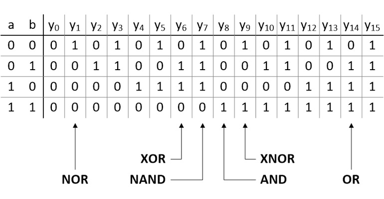
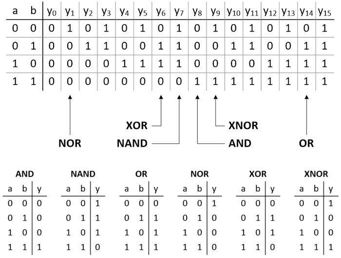
If we have a 2-input gate (we’ll call the inputs a and b), then these inputs have 22 = 4 possible combinations: 00, 01, 10, and 11. Until now, what I hadn’t consciously considered was the fact that this means there are 24 = 16 possible output permutations, which we might label y0 to y15 as illustrated below.

In reality, with the exception of y0 and y15, we could end up employing any of these permutations in a design depending on what we are trying to achieve at that time. In practice, we use some much more often than others, so we give these special names like AND, NAND, OR, NOR, etc. I don’t know about you, but—as simple and obvious as it is—I found the above way of looking at things to be strangely thought-provoking, but we digress…
The number system with which we are most familiar is decimal (aka, denary or decanary), which—as a base-10 system—has ten digits: 0, 1, 2, 3, 4, 5, 6, 7, 8, and 9. The reason for our using this system is almost certainly because (a) many peoples started counting using their fingers and (b) we have ten fingers (including thumbs) on our two hands.
Having said this, different groups of people have experimented with a variety of number systems over the years. For example, some employed a base-12 number system called duodecimal (aka, dozenal), which involves using the thumb on one hand to count the three joints on each of the remaining four fingers on the same hand. This explains why we have 24 hours in a day (2 x 12), and why we have special words like dozen (12) and gross (12 x 12 = 144).
The Maya and the Aztecs used a base-20 system called vigesimal based on counting using both fingers and toes. More recently, vigesimal systems have been employed by the Ainu of Japan, the Inuit of Alaska, Canada, and Greenland, and various peoples in Africa and Asia. This explains why we have special words like score (20), as in “The days of our lives are three scoreyears andten” (meaning 70 was considered to be a nominal human lifespan).
Last, but not least (at least for this column), the ancient Sumerians, and later the Babylonians, enjoyed a base-60 system called sexagesimal (aka, sexagenary), which is why we have 60 seconds in a minute and 60 minutes in an hour. They also made use of base-6 and base-10 as sub-bases (6 x 10 = 60), where base-6 is called senary (aka, heximal, or seximal), which explains why we have 360 degrees in a circle (6 x 60).
I don’t know about you, but I love this stuff!
However, we are in danger of wandering off into the weeds, as it were. As we’ve already noted, at their core, digital computers are based on binary because it’s relatively easy to implement logic functions that can detect and generate two different voltage values. Having said this, when people started creating the first electromechanical and electronic computers circa the 1940s, the use of binary was not well known, and its advantages were not widely understood. Thus, a lot of the early computers like ENIAC, the IBM NORC, and UNIVAC were decimal machines, which means they represented and manipulated both data and addresses as decimal values in a form known as binary coded decimal (BCD).
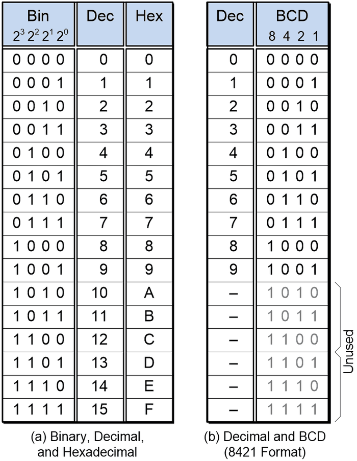
Like decimal, binary is a place value number system, which means each column in the number has an associated “weight.” The value of each digit is established by multiplying that digit by its column’s weight. In the case of a 4-bit binary value, starting with the rightmost bit, which is known as the least-significant bit (LSB), the weights are 20 = 1, 21 = 2, 22 = 4, and 23 = 8 as illustrated in (a) below. Four bits provide 24 = 16 different combinations of 0s and 1s, which we can use to represent positive values in the range 0 to 15 in decimal, or 0 to 9 and A to F in hexadecimal.

If we wish to use a four-bit binary value to represent only the decimal digits 0 through 9, then there are a variety of encodings we can use. The most common encoding employs column weights of 8, 4, 2, and 1, as illustrated in (b) above, so this is officially known as BCD 8421. However, since this is the most common form of BCD encoding, people typically just say BCD for short. Also, since these column weights are the same as those used for the natural binary count sequence, this form of encoding may also be referred to as natural BCD (NBCD) or simple BCD (SBCD).
What we want to do now is to create a logic function that can add two BCD 8421 digits together, along with a carry-in bit from a previous stage. This function will generate a 4-bit sum, along with a carry-out bit to the next state.
Considering alternative implementations will be the topic of my next column. In the meantime, why don’t you treat this as a logical conundrum and see if you can come up with your own solution (without cheating and looking on the Internet LOL). Until next time, have a good one!
About the Author(s)
You May Also Like


.jpg?width=300&auto=webp&quality=80&disable=upscale)

