Constants of Transmission Lines That Influences their Performance
The purpose of a transmission network is to transfer electrical energy from generating units at various locations to the distribution system which will finally supply the consumers. Transmission line also interconnects neighbouring utilities which permit not only economic dispatch of power within regions during normal condition but also the transfer of power between areas during emergencies.
Transmission lines in a power system show the electrical properties of resistance, inductance, capacitance and conductance. The inductance and capacitance are as a result of the effects of magnetic and electric fields around the conductor. These parameters affect the way in which these transmission lines fulfil it functions.
The transmission line is a medium for transmitting electrical energy from one place to another. Transmission lines are used between transmitter and receiver with the help of ‘’antenna’’ as, linking element. It may consist of a pair of uniform wires throughout their entire length. Thus the transmission line utilises its conducting medium transporting electrical energy from one place to another place by using electrical conductors. It may be open wire (e.g. telegraph or telephone lines) or insulated (e.g. underground cable or submarine cable)
Functions of Transmission Line
- To transmit electrical energy from one place to another place,
- To transmit communication signal from a transmitter to receiver,
- To work as circuit element like inductor, capacitor, transformer, filter, etc. mainly at high frequency,
- To act as measuring device to obtain impedance matching between source and load.
Transmission is predominantly by overhead, although, underground ac transmission would be a solution to some of the environmental and aesthetic problems involved with overhead transmission lines, there are technical and economic reasons that make use of underground ac transmission unattractive.
Faraday Law of Electromagnetic Induction
Michael Faraday (1791-1867) was in a class of his own as an outstanding experimentalist and achieved so much with very little formal academic training. He came from a humble background and served seven years as a bookbinder´s apprentice. Nonetheless, Faraday was a voracious reader of scientific works, and at the age of 20, after listening to a lecture by Sir Humphry Davy, he reached out to Davy requesting that he be given a chance to prove himself as an assistant.
In 1831, Faraday demonstrated that electricity could be produced from magnetism. He proved that induced current could be made to flow in a circuit whenever when one of these happens:
Current in a neighbouring circuit is established or interrupted,
A magnet is brought near a closed circuit, and
A closed circuit is moved about in the vicinity of a magnet or other closed current-carrying circuits.
The figure below shows one of the experiments made by Faraday. When he closed the switch, he was able to see a deflection in the galvanometer connected to the second circuit. Also, upon opening the switch, he again observed a deflection but this time, in the opposite direction.
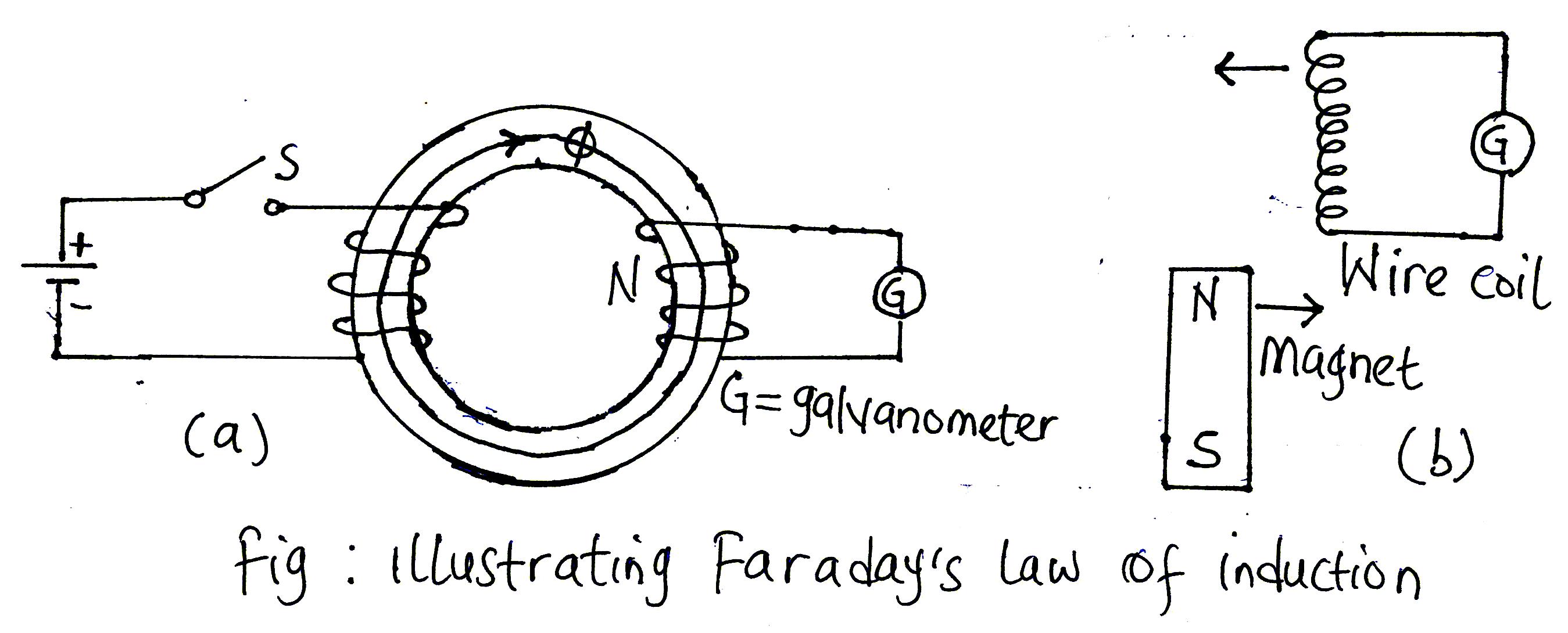
Figure (b) shows the schematic of another arrangement used by Faraday to demonstrate how electricity is produced from magnetism. The magnet was made to move toward the circuit or the circuit toward the magnet; both registered a deflection in the galvanometer.
Faraday was a dedicated and careful experimenter who kept complete records of his laboratory work. From these experiments, gave birth to Faraday´s law of induction mathematically as follows: e=-dλ/dt=-N dϕ/dt V...(1)
The quantity e denotes the electromotive force induced in a closed circuit having a flux linkage of (lambda symbol) weber-turns. In those cases where the magnetic flux cuts all the turns of the coil as shown in fig. The second form of Eq. (1) may be used to express Faraday's law. The negative sign is due to Emil Lenz, who after Faraday´s experiment pointed out that the direction of the induced current is always in a direction as to oppose the action that initiated it. This reaction is commonly called Lenz law.
Faraday’s law as embodied in Eq. (1) and is one of the two basic relationships that formed the basis of the entire theory of electromagnetic and electromechanical energy conversion. Faraday was the first to identify the emf of self-induction which is brought about whenever we disconnect circuits carrying currents in long wires or circuits wound with many turns.
The American inventor Joseph Henry also discovered on his own the current of self-induction but not before Faraday. Both experimenters were able to show that a changing current produced an emf of self-induction in a coil of wire which varied directly with the time rate of change of current. Expressed mathematically,
e=L di/dt………………(2)
Where L is a proportionality factor called the coefficient of self-inductance which is dependent upon the medium and some physical dimensions. This result is equivalent to Faraday’s law of induction as expressed in Eq. (1)
Eq. (2) is extremely important in the development of electric circuit theory. It serves to identify one of the three primary circuit parameters—inductance. The other two parameters, resistance and capacitance which we are yet to discuss
An electric transmission line has four constants which influence its ability to fulfil its obligation as part of a power system. These parameters include:
- Resistance
- Inductance
- Capacitance
- Conductance
Resistance
The resistance of the conductor is very important in transmission efficiency evaluation and economic assessment.
Effective resistance of a conductor is
R = (Power loss in a conductor)/(I2) A
Effective resistance can only be equal to the resistance only if there is uniformity in the flow of current throughout the cross-section of the conductor.
We are aware that ac voltage alternates and if the conductor is viewed as being made up of tiny annular filaments or strands. The alternating current tends to leave the strands towards the centre of the conductor and concentrates at the other periphery (skin) of the conductor due to the higher inductance of the inner strands. We should recollect that alternating current flow give rise to alternating flux which in turn induces emf of self-induction.
This flux does not link the outermost strands of the conductor but links that of the inner strands close to the centre and as such as the frequency increases, the current tends to flow at the skin of the conductor. This effect is predominant with conductors of large diameter, especially solid conductors. That is why overhead transmission lines are often stranded. Stranding reduces the skin effect while also increases the flexibility of the overhead line conductors.
DC resistance is given as Rdc = ρl/A
Where ρ = conductor resistivity
L = conductor length
A = conductor cross-sectional area
The conductor resistance is affected by three factors, frequency, spiralling and temperature.
We have talked about the effect of frequency which brings about the skin effect.
Spiraling of conductors makes the strands longer than the finished conductor. This results in a slightly higher resistance than the value calculated from Rdc = ρl/A
The conductor resistance increases as the temperature increases. This change can be considered linear over the range of temperature normally encountered and may be calculated from: (R2)/(R1) = (T+t2)/(T+t1)
where R2 and R1 are conductor resistances at t 2and t1 respectively. T is a temperature constant that depend on the conductor material for aluminum, T = 288
Current distribution is only uniform for dc.
Conductance is not as popular as the first three parameters because it is just a small fraction of shunt admittance and there is no accurate way of taking it into account. It is quite variable and often results from leakage at insulators. It changes appreciably with atmospheric conditions and with the conducting properties of dirt that collect on insulators. Corona which results from leakage between lines also varies with changes in climatic conditions. Fortunately, it is quite some negligible portion of the shunt admittance.
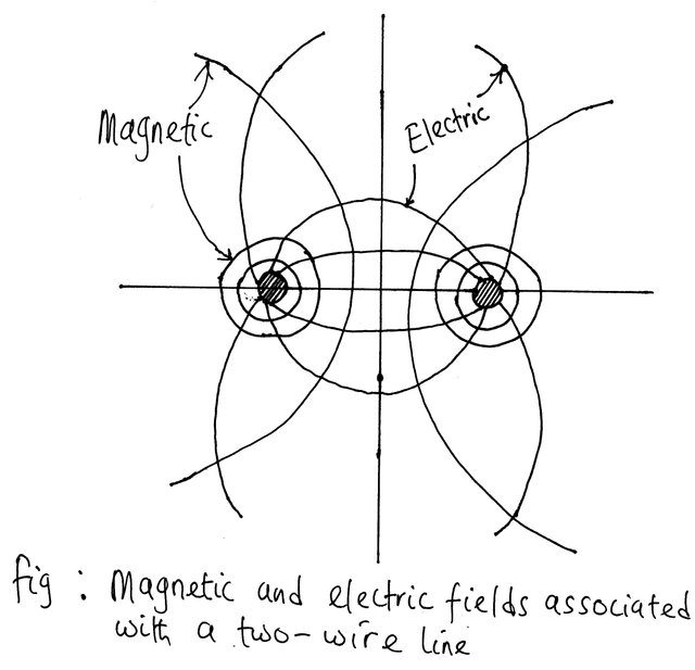
Some of the properties of an electric circuit are as a result of electric and magnetic fields which accompany its current flow.
Consider the figure below of a single phase line and its corresponding magnetic and electric fields. The lines of magnetic flux form closed loops linking the circuit, and the lines of electric flux originate on the positive charges on one conductor and terminate on the negative charges on the other conductor. When the current in the conductor varies, there will be a change in the number of lines of magnetic flux linking the circuit. Whenever there is a change in the number of lines of magnetic flux linking a circuit, a voltage will be induced in the circuit which is proportional to the rate of change of flux.
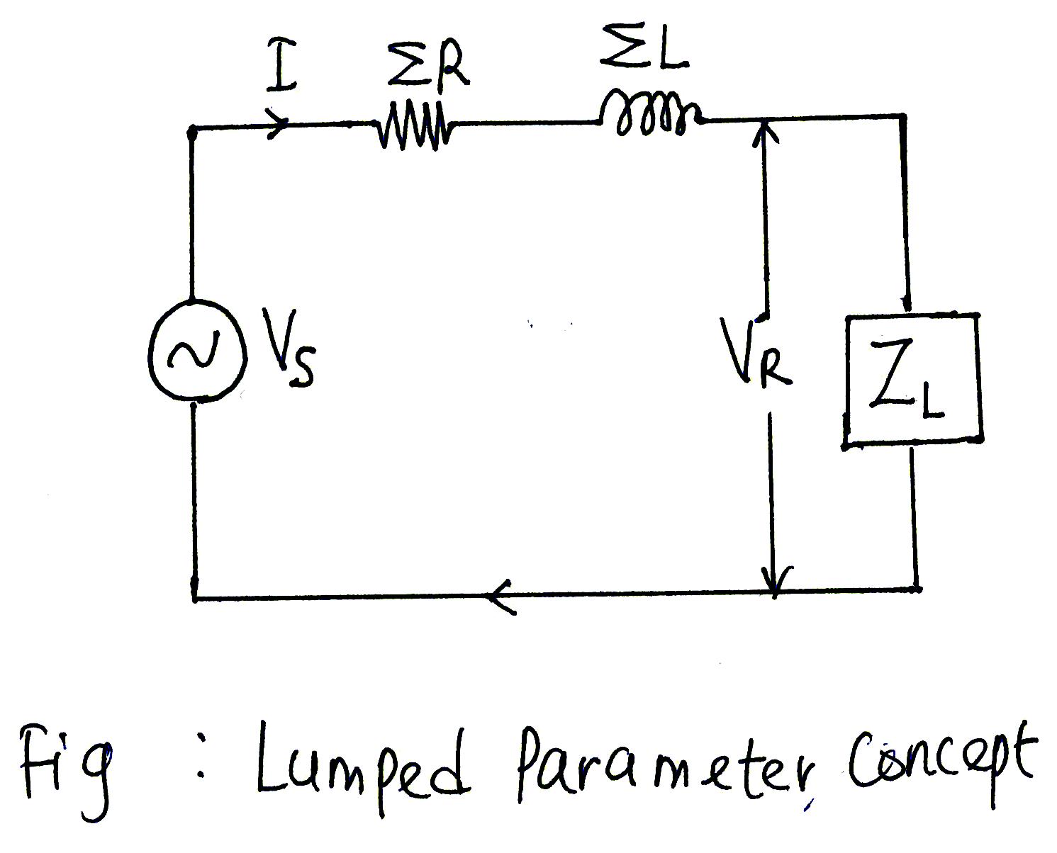
The inductance of the circuit relates the voltage induced by changing the flux to the rate of change of current. The capacitance which exists between the conductors is defined as the charge on the conductors per unit potential difference between them. The resistance and inductance are uniformly distributed along the line to form the series impedance.
The conductance and capacitance existing between conductors of a single-phase line or form a conductor to the neutral of a three-phase line form the shunt admittance.
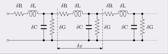
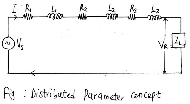
Although the resistance, inductance and capacitance of transmission lines are distributed, the equivalent circuit of a line is made up of lumped parameter especially for short length line (<80km) and a medium length line (80km-250km) magnetic flux linking the circuit with reasonable accuracy.
Long transmission lines rely on the distributed parameter concept to achieve a reasonable level of accuracy. Any change in the flux linking a circuit induces a voltage in the circuit which is proportional to the rate of change of flux. The inductance of the circuit relates the voltage induced by changing flux to the rate of change of current.
Capacitance
The capacitance which is found between the conductors can be defined as the charge on the conductors per unit of potential difference between them. As a result of the potential difference between the conductors of transmission lines conductors, there exist a capacitance between them.
We are aware that when two conductors or electrodes are separated by an insulator (dielectric), there exist capacitance between them but in the case of an overhead transmission line, the air which separates the conductor acts as an insulator.
This capacitance exists between the conductors because electric field exists around a conductor carrying current. The lines of electric flux emanate from the positive charges on the conductor and terminate on the negative charge on the other conductor. The ratio of charge on the conductors per unit of potential difference between them is the capacitance between the conductors.
Electric and Potential Difference
Consider a point charge that is positively charged as illustrated in the figure below. Consider a second test charge that is positively charged and thirdly, consider another test charge that is positively charged. We are aware from the Coulomb’s experiment that like charges repel but unlike charges attract and that the force of attraction or repulsion is equivalent to the product of the charges but inversely proportional to the square of the distance separating them.
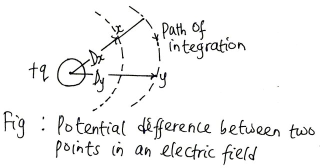
With this knowledge, we can decide to locate the first point charge at a specific location in the space. The second and third point charges could be placed at infinity. Infinity is so far away that the forces of attraction or repulsion will be zero. But assuming we move these two point charges say Q2 and Q3 to a distance closer to Q1, we will notice that as we near Q1, more and more work will have to be done to maintain Q2 and Q3 at their respective positions. Q2 is closer to Q1 (from the diagram) while Q3 is a bit farther.
Work done on Q2 is greater because more significant work is done against the electric field of Q1 for it to remain there. This work is recoverable as kinetic energy in the event the force holding it at that position is removed. When this is done, Q2 will head to the direction of infinity from where it was placed initially.
The same thing goes for Q3 only that the force holding Q3 at that point is smaller than that of Q2.
Thus, Q2 is at a higher potential than Q3. If Q2 moves from a distance Dx to a distance Dy, it expends or loses energy while if Q3 moves from its position Dy to Dx, it gains energy.
The potential difference between Q2 and Q3 can be gotten from the knowledge of electric field strength since electric field strength is the negative of potential difference. By integrating the electric field strength which is given as E=q/2πεx volts from Dx to Dy, we will get the potential difference which is V. We can calculate capacitance C from knowledge of V.
We know that capacitance is charge per unit potential difference, i.e. C = Q/V
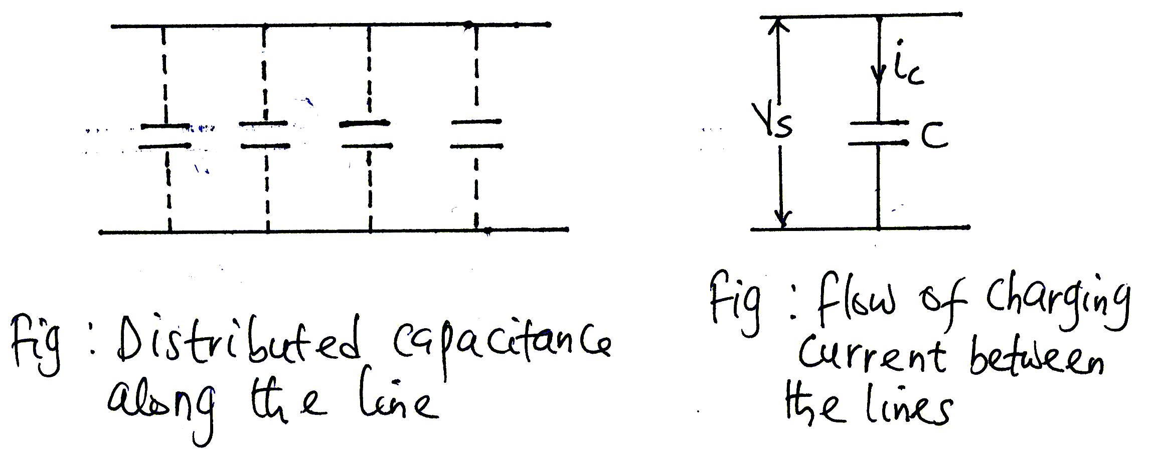
An alternating voltage impressed on a transmission line causes the charge on the conductors at any point to increase and decrease with the increase and decrease of the instantaneous voltage between the conductors that point. The flow of charge is a current and the current caused by the alternate charging and discharging of the line due to the alternating voltage is called the charging current of the line. Charging current flows in a line even when the line is open circuited and it affects the voltage drop, efficiency and power factor of the line.
Ferranti Effect
A long transmission line draws a significant quantity of charging current. If the line happen to be open circuited or lightly loaded at the receiving end, the voltage t the receiving end would tend to be higher than that at the sending end.
This phenomenon is known as Ferranti effect and results from the voltage drop across the series inductance of the transmission being in phase with the sending end voltage. This means that both capacitance and inductance of the transmission line both contributes to the occurrence of this phenomenon.
For short lines, the capacitive charging current is negligible and has no such effect. But the effect becomes more substantial and appreciable when the length of the line exceeds 80Km and as such this phenomenon is pronounced in medium and long lines.
A greater percentage of all electrical loads are inductive nature, and they consume lots of reactive power from the transmission line.
To cancel the effect of the inductive nature of the loads at the receiving end, a capacitance is connected in parallel at the receiving end to supply the reactive power and cushion the effect of the excessive consumption of Mvar by the inductance.
As the inductive load rises, more capacitance of the same counter effect is connected using electronic switching. This results in stability as reactive power consumed by the inductive loads are supplied by the capacitors.
Many times, when the inductive load drops or are switched off, the capacitors could still be in the circuit. This means that the reactive power supplied by the capacitors will now exceed that of the one consumed by the inductive loads and this adds on to the transmission line. The result is that the voltage at the receiving end will now exceed that of the sending end.
Why does voltage at the receiving end exceeds that of the sending end voltage at the lightly loaded line?
The Ferranti effect occurs when the charging current of the distributed capacitance exceeds that of the current associated with the load at the receiving end.
It is now easy to see why the Ferranti effect is more prevalent in lightly loaded line as compared to a fully loaded line. Remember that the charging current flows through the capacitance which is a shunt between the transmission line and will always flow irrespective of whether the line is lightly loaded or fully loaded.
This effect is as a result of the voltage drop in the line inductance (due to charging current) being in phase with the voltage at the sending end.
The voltage diminishes the sending end voltage and adds it to the receiving end voltage and as such the receiving end voltage becomes greater than the sending end voltage.
The capacitive effect is constant whether the line is loaded or not and as a result, it poses no problem to the lines that are loaded. If the inductive load is present, the VAR generated by the line capacitance is consumed by the load.
To reduce Ferranti effect, it is customary to regulate the line voltage by compensating the line inductance by placing capacitance in series with it and the line capacitance to earth by shunt reactors. Series capacitors are positioned at different places along the line while shunt reactors are usually installed in stations at the ends of the line.
By doing so, the voltage difference between the ends of the line is minimised, both in amplitude and in phase angle.
Another way of stabilising the voltage at the receiving end is to install hunt reactors at junctions where several lines meet.
Conclusion
Just like we said before, the parameters of the transmission line affect the way in which these transmission lines fulfil its functions. One of the functions of the transmission line is to transmit electrical energy from one place to another place, at a specified voltage and frequency, and as such the voltage of a transmission line should remain as constant as possible even under variable load conditions. Unfortunately, the voltage profile along the line is dependent on the loading conditions, sudden load rejection and line rejection and line energization have the effect of raising the voltage at the end of the line to a dangerously high level.
An increase in length reduces the maximum power transfer capability of the line, thereby reducing the margin between the planned power transfer and the maximum limit at which the line is susceptible to transient and dynamic stability
Electrical appliances are designed to work at a specific voltage. If the voltages vary beyond the allowable limit at the consumer ends their equipment may get damaged, and their windings may burn out because of high voltage. Ferranti effect on long transmission lines at light load or no load increases the receiving end voltage. This voltage can be regulated by placing the shunt reactors at the receiving end of the lines.
Shunt reactor is an inductive current element sandwiched between line and neutral to cancel the capacitive current from transmission lines. When this effect occurs in long transmission lines, shunt reactors compensate the capacitive VAR of the lines, and therefore the voltage is maintained within the prescribed limits.
The way out is to provide additional reactors to improve reactive power compensation.
This is a test comment, notify @kryzsec on discord if there are any errors please.
Being A SteemStem Member
This could easily serve as lecture notes for introduction to transmission transmission lines modelling. I am sure that those without electrical background would agree that this post is well written and illustrated. I did not know about the Ferranti effect so I'm glad I learned it. I guess what happens in Ferranti effect could be explained by electromagnetic induction. That happens as a wave travels in a medium.
Awesome! Upvoted and resteemed!
Thanks for deeming the work worthy of resteeming and upvote. It is a thing of joy when to know that you learned one or two things from the post. Thanks for everything.
I have been wondering how the receiving end voltage would be larger than the sending end voltage with the voltage drops across the resistance, inductance and capacitance. But now I fully understand the concept after reading about the Ferranti effect. A clear post with detailed illustrations to drive your points home. Keep it up. Thanks for sharing.
Ferranti effect is an interesting phenomenon and it is as result of voltage drop across the inductance of the transmission line being in phase with the sending end voltage, especially during the period of light load. Thanks for making out time to visit my blog.
You have reminded me of my elementary physics days. I think I last did this in 2008. The study of the ionosphere has taken over..hahaha
it was quite refreshing reading this
It is good to have folks like you here that have patients to read through a posts. I am delighted it made sense to you. Thanks for your time and comment. I sincerely appreciate it.
This is more like a reminder;