
Introduction to Waveplates and Retarders
What are Waveplates and Retarders?
Waveplates and Retarders are important optical components to manipulate and alter the polarization state of laser light.Waveplates are conventionally made by birefringent crystals such as Quartz, Magnesium Fluoride. (There are also Retarders made from non-birefringent materials. The Fresnel Rhomb Retarder is an excellent example, which is usually made from BK7, UV Fused Silica, or ZnSe, realizing the phase delay by utilizing the Total Internal Reflection. The retardation generated by a Fresnel Rhomb depends virtually solely on the refractive index and the geometries of the prism. Which we will be discussing in the sections below.)
The anisotropy of these crystal materials results in the separation of one light beam into two light rays when hitting the interface. The two split light rays encounter different refractive indices: one called the Ordinary Ray, which is governed by the ordinary refractive index, and another called the Extraordinary ray, which is governed by the direction-sensitive extraordinary refractive index. The two rays always have their polarization direction perpendicular to each other.
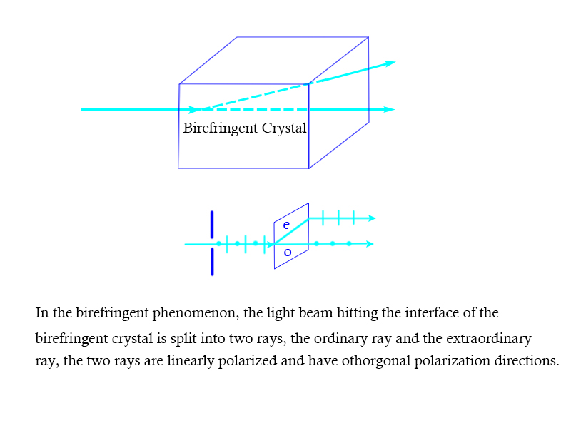
Figure 1. The Birefringent Phenomenon
Waveplates are purposefully sliced so that their optical surface is parallel to their optical axis, in which case the ordinary ray and the extraordinary ray will experience different refractive indices and hence travel in different phase velocities. The axis in which the polarized electric vector travels with a greater velocity (Vfast=c/Nfast) is defined as the Fast axis, and the one in which the electric vector travel with a lower velocity (Vslow=c/Nslow) as the Slow axis. The two axes are always orthogonal.
When a light beam is projected normal to the surface of a waveplate, different phase velocities of the two components will naturally introduce phase delay between the fast and the slow components, where the slow components will be several phases (or a fraction of phase) lagged behind the fast component. The magnitude of the phase delay is called Retardation. The retardation of a waveplate could be formulated as below:
ReTardation=2πL(Nslow-Nfast)/λ
Where L is the distance traveled by the incident light (the thickness of the waveplate), Nfast and Nslow are the refractive indices along the fast and slow axis respectively.
The value of retardation might be written in various forms, for example, a “half-wave” retardation is equivalent to a retardation value of π radians or lambda/2.
From the equation above, it could be easily deduced that by deliberately designing the thickness of the waveplates, the desired retardation could be obtained. However, besides the thickness of a waveplate, other external factors will affect the retardtion value, for example, the wavelengths of the incident light, the temperature of the operation environment, the angle of incidence, etc. The changes of retardation caused by external factors are often disturbing and detrimental, and are what the manufacturers trying their best to avoid. A Zero Order Waveplate effectively attenuates the inconsistency of retardation by aligning two waveplates together with their axes crossed, and an achromatic or a super achromatic waveplate explores the different birefringent properties of two birefringent materials, which helps to eliminate chromatic dispersion and to realize the broadband application.
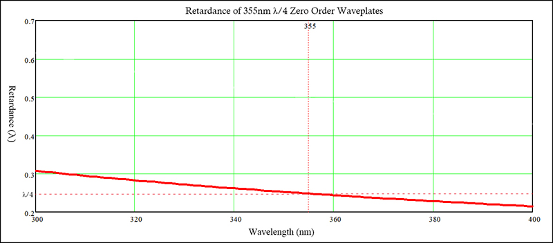
Figure 2. The graph above illustrates the change in retardation via a wavelength spectral for 355nm, Zero Order Quarter Waveplates of Quartz.
How to use a Half Waveplate or a Quarter Waveplate?
The most widely applied retardation values are half-wave retardation and quarter-wave retardation. What do half waveplates and quarter waveplates do?
Half Waveplate
The distinctive feature of a half wave plate is that it produces a half phase delay (lambda/2 retardation) between the fast and slow components. However, in real-life applications, the retardation could either be exactly lambda/2 or lambda/2 plus several full wavelengths, since the light wave repeats itself every 2π radians, theoretically these extra wavelengths will not affect the result achieved. (To be more specific, only Half Waveplates with Zero Oder retardation generate exactly one half phase delay, while in the case of Multiple or Low Order Half Waveplates, the phase delay will be one half plus several full wavelengths.)
When linearly polarized light is projected normally to the plane of cut, with its polarization plane making an angle of α to the fast(or slow) axis of the half waveplate, the polarization plane of the incoming light will undergo an angle rotation of 2α when exiting. This key feature of half waveplates makes them multi-functional for various optical applications.
The fast (or slow) axes are vital, However, it is likely that the axes are not indicated or the indications are blurred, there is a simple method to help you find the axes. First place a polarizer in front of the laser device, tilt the polarizer until the light extinct, then interpose the waveplate between the laser device and the polarizer, rotate the waveplate so that the eventual light output is still extinct——and viola! you have found an axis successfully!
Plane Rotation:
Most lasers are horizontally polarized, but if the system requires the laser light to reflect off a metallic surface because mirrors work best with vertically polarized light this could be problematic. The solution is simply to place a half waveplate, with its fast(or slow) axis making an angle of 45 degrees to the horizontally polarized light, the emerging laser light will be vertically polarized as desired, without attenuating the original light intensity.
If you want to rotate the plane of polarization by angles other than 90 degrees, just orient the axis of the half waveplate at half of the angle you wanted to the original polarization plane.
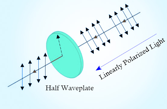
Figure 3. Using a Half Waveplate for Plane Rotation
Optical Attenuator
An optical attenuator is a device used to reduce the optical power of a light beam. One could obtain an optical attenuator by combining a polarizer and a half waveplate.
The half waveplate in the middle then rotates the polarization direction, after passing another polarizer, optical attenuation is realized. The actual ratio of optical attenuation depends on the angle between the polarization direction rotated by the half waveplate and the polarization direction of the polarizer. However, this type of optical attenuator is more feasible for linearly polarized systems and more difficult to realize in systems without a certain polarization state.

Figure 4. Using a Half Waveplate as an Optical Attenuator
Variable Ratio Beam Splitter
Variable Ratio Beam Splitters are devices for controlling the intensity of light. One may obtain a variable ratio beamsplitter by combining a half waveplate and a Polarizing Beam Splitter.
Firstly the incident light beam of linear polarization travel through the half waveplate, and its polarization direction is altered. The exiting light beam then passes the beam splitter, where it is divided into two orthogonal light beams. By rotating the half waveplate intensity modulation could be realized.
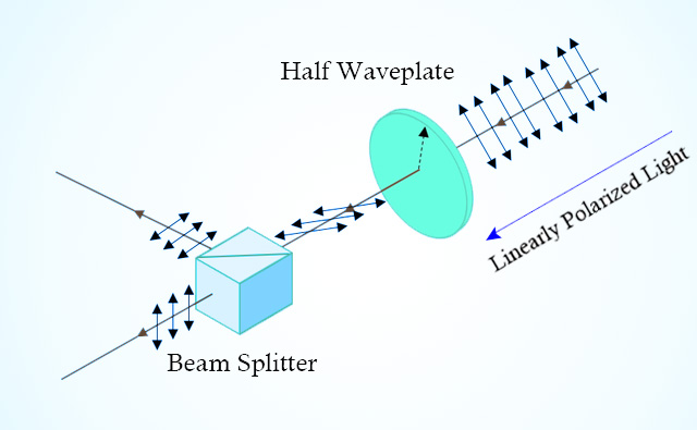
Figure 5. Using a Half Waveplate as a Variable Ratio Beam Splitter
Polarization State Generator
One may obtain a polarization state generator by combining a half waveplate and a quarter waveplate. The operating principle of this set of waveplates is that, when a linearly polarized light is projected to the surface of the half waveplate if the directions of the fast axes of the two waveplates align completely, the output light beam will remain linearly polarized, in this case, the half waveplate could be used to alter the direction of polarization of the light beam. If the directions of the fast axes of the quarter waveplate and the half waveplate do not match, then the output light will be either circularly or elliptically polarized, where the ellipticity and the direction of rotation(clockwise or anti-clockwise) could be modulated using the quarter waveplate.
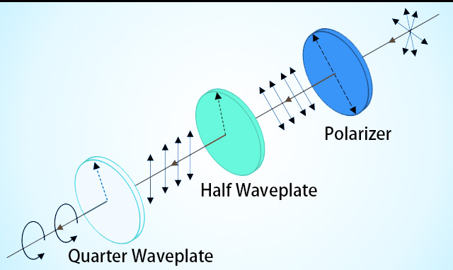
Figure 6. Using a Half Waveplate as a Polarization State Generator
Quarter waveplate
In contrast to half waveplates, the quarter waveplates produce a phase delay of a quarter wavelength between the fast and slow components. If the quarter waveplate is oriented 45° to a linearly polarized light beam, the output light beam would be circularly polarized and vice versa. This is because after the light beam passes the waveplate, the lambda/4 phase difference between the fast and slow components causes a rotation of a helix form in the total electric vector in a period of exactly one wavelength, which is how circular polarization is defined.
How to use a quarter waveplate for the conversion of linear polarization into circular polarization? First, find the fast(or slow) axis of the waveplate. If the fast axes of a quarter waveplate are not indicated, the method to find its axes is identical to that of the half waveplate: Place a polarizer, with its polarization plane orthogonal to the polarization plane of the incident light to exterminate the light, then interpose the quarter waveplate and oriented it so to retain the extinction. After finding the axes, adjust the position of the quarter waveplate so that the angle between the polarization direction of the incident light and the fast(or slow) axis is 45°, at this stage circularly polarized light should be obtained.
The procedure of using a quarter waveplate to convert circularly polarized light into linearly polarized light could be deduced from above.
Optical isolator
One may obtain an optical isolator by combining a polarizer, a quarter waveplate, and a mirror, the quarter waveplate is sandwiched in the middle of the other two. The transformation procedure is: At first the input light is linearly polarized by the polarizer, then the light passes the quarter waveplate and becomes circularly polarized. After being reflected back by the mirror, light encounters the quarter waveplate again and is transformed back into linear polarization, but with its plane of polarization rotated by 90º. This time the rotated light will be eventually rejected by the polarizer.
Types of Waveplates and Retarders
Understanding different types of Waveplates and Retarders are equally as important as figuring out their working principle, especially for buyers. Don’t worry, Shalom EO edited a brief guide for you, after reading that you might have a much clarified and profound understanding of waveplates.
Low Order Waveplates or Multiple Order Waveplates
Due to difficulties in the manufacturing stage, it could be hard to churn out large quantities of waveplates that are ultra-thin and which produce exactly the desired fractional retardance. The Low Order Waveplates, Or Multiple Order Waveplates are relatively thick and generate the desired retardation with several additional wavelengths of phase delay. Because light waves repeat themselves periodically, a low order half waveplate, which produces a phase delay of lambda/2 plus 3 additional lambdas could also function as a half waveplate. The word “Order” here refers to the number of additional wavelengths generated. In this text, a low order waveplate is better than multiple order waveplates because it produces less addition phase delay and its retardation is more precise. However, the surplus of retardation also implies that they are much more sensitive to changes in wavelengths, temperature, or the AOI than their zero order counterparts.
Generally speaking, if you are looking for cheap buying-in-bulk waveplates for single wavelength applications, then Low Order Waveplates are just right for you. Shalom EO offers Low Order Waveplates of two material options (Quartz for Visible to Near-IR spectral or MgF2 for greater wavelengths up to 7000nm).
Zero Order Waveplates
Zero Order Waveplates are essentially comprised of two multiple order or low order waveplates with their axes orthogonally aligned (aligning the fast axis of one waveplate to the slow axis of the another), the resulting retardation is the difference between two individual retardations produced by respectively by the two constituent waveplates. By combining two single waveplates together, Zero Order Waveplates effectively offset the impacts of external factors (wavelength change, ambient temperature) on the retardation, which means the retardation will be much more constant compared to the low order waveplates, making them competent for applications involving broadened wavelength. Nevertheless, they might still have rather susceptive responsiveness to variations of the angle of incidence.
Shalom EO offers three types of Zero Order Waveplates: Air spaced Zero Order Waveplates, Optically Contacted Zero Order Waveplates and NOA61 Cemented Zero Order Waveplates. While the cemented zero order waveplates are the common alternative, for high energy operations, consider Air spaced zero order waveplates and optically contacted zero order waveplates, since the two types have relatively higher damage threshold than the cemented versions.

Figure 7. This curve shows the changes in retardation of a 1064nm Zero Order Half Waveplate of Quartz along with the variation of wavelength
True Zero Order Waveplates
True Zero Order Waveplates are waveplates of single-plate structure and provide exactly the required retardation, therefore its thickness is usually only several micrometers. Although requiring relatively strict processing, the contracted thickness contributes to more superior retardation constancy against wavelength variations or climate changes than conventional Zero Order Waveplates. Shalom EO offers True Zero Order Waveplates made from Quartz (for 532-3000nm) or MgF2 (for long-wavelength applications from 3000-7000nm), the single plate versions are relatively fragile but are of high damage threshold, while the versions cemented with BK7 substrates are much easy to handle, but are of lower damage threshold.
Achromatic Waveplates
Achromatic Wavepltes are constructed by one MgF2 Waveplate and one Quartz Waveplates with their axes orthogonally aligned, of which the birefringent properties are complementary, achieving the required focal length while minimizing chromatic dispersion. Through this approach the intrinsic influence of wavelength shifts on the retardation is drastically reduced, making achromatic waveplates even more retardation-constant than zero order waveplates, thus eminent for various Broadband applications spanning wide spectral ranges (e.g. from 900-2000nm). Two application examples are Tunable laser sources, Femtosecond laser systems, etc.

Figure 8. This curve shows the changes in retardation of a 690-1200nm Achromatic Quarter Waveplate along with the variation of wavelength
Super Achromatic Waveplates
Super Achromatic Waveplates are virtually an upgraded version of achromatic waveplates. The operation principle of super achromatic waveplates is the same as that described of achromatic waveplates. Super achromatic waveplates are also compounded by two crystal materials (e.g. quartz and magnesium fluoride), but instead of two as in the case of achromatic waveplates, they consists of six single waveplates (three of Quartz, three of MgF2), the result is exceedingly flat retardation over even wider wavelength ranges.
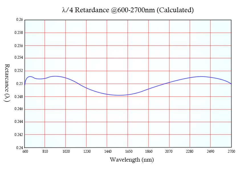
Figure 9. The Retardation Curve of a 600-2700nm Super Achromatic Quarter Waveplate, from the graph one could observe that the super achromatic waveplate performs almost flat retardation spectrally.
Fresnel Rhomb Retarders
Fresnel Rhomb Retarders operates upon an entirely different principle other than exploiting the birefringence. A Fresnel Rhomb introduces phase difference between the components of light using total internal reflection. When light is projected on the interface, the electric field of the light wave splits into two perpendicular components, the s component, and the p component. The rhombs are strategically processed into the shape of a right parallelepiped, so that with the angle of incidence cautiously chosen, the p component will proceed lambda/8 relative to the s component at each total internal reflection underwent. When light emerges, after experiencing two total internal reflections, the p component will eventually be lambda/4 ahead of the s component, thus realizing the same function of a Quarter Waveplate. When constructing a Half Wave Fresnel Rhomb Retarder, two rhombs are cemented in tandem to avert reflections at the interface.
The Fresnel Rhombs are usually made from glass materials, which are non-birefringent, the typical three being BK7, UV Fused Silica, or ZnSe. Because the retardation introduced by the rhomb is related to the refractive index, which only varies slightly over a wide wavelength range, the Fresnel Rhomb Retarders have even broader wavelength capabilities than other broadband waveplates such as achromatic waveplates.
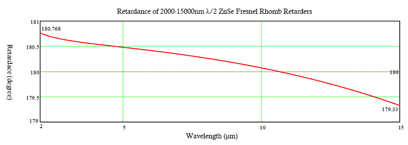
Figure 10. The curve above illustrates the superiorly broad wavelength range capability (2000-15000nm) of a Half Fresnel Romb Retarders of ZnSe.
Dual Wavelength Waveplates
Dual Wavelength Waveplates introduce two retardation values for two wavelengths through the fitting of the refractive index at different wavelengths. Dual Wavelength Waveplates are particularly useful when used in conjunction with other polarization-sensitive components to separate coaxial laser beams of different wavelengths or elevate and promote the conversion efficiency of Solid State SHG Lasers. Additionally, Dual Wavelength Waveplates could also be applied to THG Systems. Triple Wavelength Waveplates could also be customized by Shalom EO at your request.
Comparison Chart of Waveplate Types
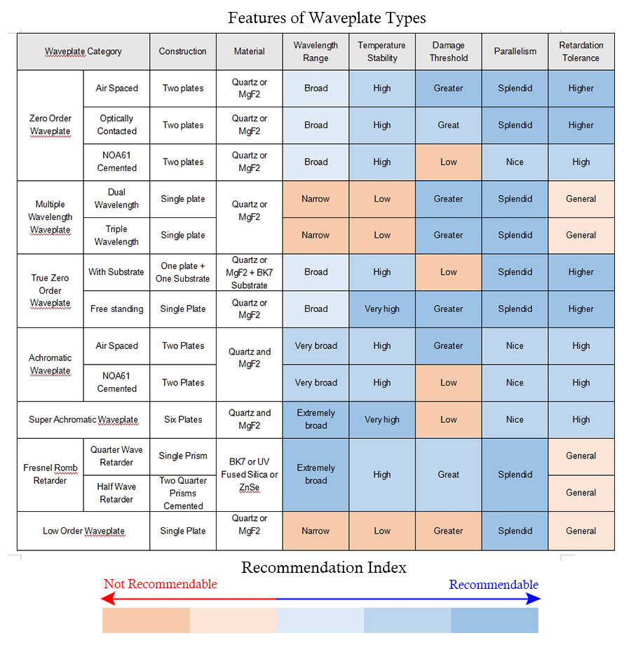
The features of different types of Waveplates and Retarders are summarised in the chart above. This comparison chart is very instructive for buyers, reading it carefully might help you select the waveplate type of your interest.
Adjustments of Waveplates
Additionally, It might happen that you find the waveplates you bought might not produce exactly the designed retardation. There are plenty of reasons: e.g. the waveplates are not designed for your wavelength of interest, or there are external factors such as temperature affecting the retardation. The small deviations could be modified by rotating the plane of polarization towards the fast or slow axis of the waveplate. Moving towards the fast axis reduces the retardation while moving towards the fast axis raises the retardation. Try both directions and keep checking the improvements using polarizers.
Related Products


Tags: Introduction to Waveplates and Retarders