chapter 12 Counting Systems
Radiation counting systems are used for a variety of purposes in nuclear medicine. In vitro (from Latin, meaning “in glass”) counting systems are employed to measure radioactivity in tissue, blood, and urine samples; for radioimmunoassay and competitive protein binding assay of drugs, hormones, and other biologically active compounds; and for radionuclide identification, quality control, and radioactivity assays in radiopharmacy and radiochemistry. In vitro counting systems range from relatively simple, manually operated, single-sample, single-detector instruments to automated systems capable of processing hundreds of samples in a batch with computer processing of the resulting data.
At present, the most efficient and economical detector for counting γ-ray emissions* is a sodium iodide [NaI(Tl)] scintillation detector. The characteristics of various NaI(Tl) counting systems are discussed in Sections A and B in this chapter. Scintillation counters for β particles and low-energy x rays or γ rays are presented in Section C later in this chapter. Counting systems based on gas detectors and semiconductor detectors are discussed in Sections D and E, respectively. Section F deals with counting systems for in vivo applications, including thyroid uptake, sentinel node detection, and intraoperative probes.
A NaI(Tl) Well Counter
1 Detector Characteristics
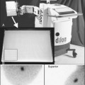
The detector for a NaI(Tl) well counter is a single crystal of NaI(Tl) with a hole in one end of the crystal for the insertion of the sample (Fig. 12-1A). Dimensions of some commonly used well detectors are given in Table 12-1. The 4.5-cm diameter × 5-cm long crystal with 1.6-cm diameter × 3.8-cm deep well, the standard well-counter detector, is the most frequently used in nuclear medicine. It is designed for counting of samples in standard-size test tubes. Very large well-counter detectors, up to 13-cm diameter × 25-cm length, have been employed for counting very small quantities of high-energy γ-ray emitters (e.g., 40K and 137Cs). Most well-counter systems employ 5 cm or greater thickness of lead around the detector to reduce background counting levels. A typical manually loaded well-counter system is shown in Figure 12-1B.


Light transfer between the NaI(Tl) crystal and the photomultiplier (PM) tube is less than optimal with well-type detectors because of reflection and scattering of light by the well surface inside the detector crystal. Energy resolution is therefore poorer [10% to 15% full width at half maximum (FWHM) for 137Cs] than obtained with optimized NaI(Tl) detector designs (approximately 6% FWHM) (see Chapter 10, Section B.7).
2 Detection Efficiency
The detection efficiency D (see Chapter 11, Section A) of the NaI(Tl) well counter for most γ-ray emitters is quite high, primarily because of their near 100% geometric efficiency g. The combination of high detection efficiency and low background counting levels makes the well counter highly suitable for counting samples containing very small quantities (Bq–kBq) of γ-ray-emitting activity. The geometric efficiency for small ( 1-mL) samples in the standard well counter is approximately 93% (see Fig. 11-3).
The intrinsic efficiency ε (Equation 11-8) of well-counter detectors depends on the γ-ray energy and on the thickness of NaI(Tl) surrounding the sample; however, the calculation of intrinsic efficiency is complicated because different thicknesses of detector are traversed by γ rays at different angles around the source. Calculated intrinsic efficiencies (i.e., all pulses counted) versus γ-ray energy for 1-mL sample volumes and for different NaI(Tl) well-counter detectors are shown in Figure 12-2. Intrinsic efficiency is close to 100% for 1.3- to 4.5-cm wall thickness and Eγ  150 keV, but at 500 keV the intrinsic efficiencies range from 39% to 82%.

FIGURE 12-2 Intrinsic efficiency (γ-ray absorption efficiency, Equation 11-9) vs. γ-ray energy for different NaI(Tl) well-counter detectors.
Intrinsic efficiency can be used to calculate the counting rate per kBq for a radionuclide if all pulses from the detector are counted; however, if only photopeak events are recorded, then the photofraction fp also must be considered (see Chapter 11, Section A.4). The photofraction decreases with increasing γ-ray energy and increases with increasing well-detector size (Fig. 12-3). At 100 keV, fp ≈ 100% for all detector sizes. At 500 keV, fp ranges from 48% to 83% from the smallest to the largest common detector sizes (Table 12-1).

The intrinsic photopeak efficiency εp is the product of the intrinsic efficiency and photofraction

This may be used to estimate photopeak counting rates. Figure 12-4 shows εp versus γ-ray energy.

FIGURE 12-4 Intrinsic photopeak efficiency vs. γ-ray energy for different NaI(Tl) well-counter detectors.
Table 12-2 lists some detection efficiencies, expressed as counts per minute (cpm) per becquerel, for full-spectrum counting of different radionuclides in the standard well counter. These values apply to 1-mL samples in standard test tubes.

3 Sample Volume Effects
The fraction of γ rays escaping through the hole at the end of the well depends on the position of the source in the well. The fraction is only about 7% near the bottom of the well but increases to 50% near the top and is even larger for sources outside the well. Thus the geometric efficiency of a well counter depends on sample positioning. If a small volume of radioactive solution of constant activity in a test tube is diluted progressively by adding water to it, the counting rate recorded from the sample in a standard well detector progressively decreases, even though total activity in the sample remains constant (Fig. 12-5). In essence, the geometric efficiency for the sample decreases as portions of the activity are displaced to the top of the well.

If the volume of a sample is increased by adding radioactive solution at a constant concentration, the counting rate first increases linearly with sample volume (or activity) but the proportionality is lost as the volume approaches and then exceeds the top of the well. Eventually there is little change with increasing sample volume, although the total activity is increasing (see Fig. 12-5). For example, an increase of sample volume in a standard test tube from 7 to 8 mL, a 14% increase in volume, increases the counting rate by only about 1%.
Thus sample volume has significant effects on counting rate with well counters. Sample volumes should be the same when comparing two samples. One technique that is used when adequate sample volumes are available is to fill the test tubes to capacity because with full test tubes, small differences in total volume have only minor effects on counting rate (curve B in Fig. 12-5); however, this requires that identical test tubes be used for all samples, so that the volume of activity inside the well itself does not differ between samples.
4 Assay of Absolute Activity
A standard NaI(Tl) well counter can be used for assay of absolute activity (Bq or Bq/mL) in samples of unknown activity using the calibration data given in Table 12-2. Alternatively, one can compare the counting rate of the unknown sample to that of a calibration source (see Chapter 11, Section A.6). “Mock” sources containing long-lived radionuclides are used to simulate short-lived radionuclides, for example, a mixture of 133Ba (356- and 384-keV γ rays) and 137Cs (662-keV γ rays) for “mock 131I.” Frequently, such standards are calibrated in terms of “equivalent activity” of the radionuclide they are meant to simulate. Thus if the activity of a mock 131I standard is given as “A(Bq) of 131I,” then the activity of a sample of 131I of unknown activity X would be obtained from

Another commonly used mock standard is 57Co (129 and 137 keV) for 99mTc (140 keV). If the 57Co is calibrated in “equivalent Bq of 99mTc,” then Equation 12-2 can be used for 99mTc calibrations also. If it is calibrated in becquerels of 57Co, however, one must correct for the differing emission frequencies between 57Co and 99mTc (0.962 γ rays/disintegration vs. 0.889 γ rays/disintegration, respectively). The activity X of a sample of 99mTc of unknown activity would then be given by

5 Shielding and Background
It is desirable to keep counting rates from background radiation as low as possible with the well counter to minimize statistical uncertainties in counting measurements (see Chapter 9, Section D.4). Sources of background include cosmic rays, natural radioactivity in the detector (e.g., 40K) and surrounding shielding materials (e.g., radionuclides of Rn, Th, and U in lead), and other radiation sources in the room. Additional sources of background in a hospital environment include patients who have been injected with radionuclides for nuclear medicine studies or for therapeutic purposes. These sources of radiation, although usually located some distance from the counter, can produce significant and variable sources of background. External sources of background radiation are minimized by surrounding the detector with lead. The thickness of the lead shielding is typically 2.5-7.5 cm; however, even with lead shielding it is still advisable to keep the counting area as free as possible of unnecessary radioactive samples.
In well counters with automated multiple-sample changers (Section A.9), it also is important to determine if high-activity samples are producing significant backgrounds levels in comparison with activity samples in the same counting rack. In many nuclear medicine procedures, background counting rates are measured between samples, but if the background counting rate becomes large (e.g., from a radioactive spill or contamination of the detector), it can produce significant statistical errors even when properly subtracted from the sample counting rate (see Chapter 9, Section D.4).
6 Energy Calibration
Energy selection in a well counter usually is accomplished by an SCA (Chapter 8, Section C.2). Commercial well-counter systems have push-button or computer selection of the appropriate SCA window settings for different radionuclides. In these systems compensation has been made by the manufacturer for the nonlinear energy response of the NaI(Tl) detector. However, because of the possibility of drifts in the electronics and the PM tube gain with time, the response of the well counter should be checked regularly with a long-lived standard source, such as 137Cs, as a quality assurance measure. Some modern well counters incorporate MCAs, allowing the entire spectrum to be measured and analyzed.
7 Multiple Radionuclide Source Counting
When multiple radionuclides are counted simultaneously (e.g., from tracer studies with double labels), there is “crosstalk” interference because of overlap of the γ-ray spectra of the two sources, as shown in Figure 12-6 for 99mTc and 51Cr. If SCA windows are positioned on the 99mTc (window 1) and 51Cr (window 2) photopeaks, a correction for the interference can be applied as follows: A sample containing only 51Cr is counted and the ratio R12 of counts in window 1 to counts in window 2 is determined. Similarly, a sample containing only 99mTc is counted and the ratio R21 of counts in window 2 to counts in window 1 is determined. Suppose then that a mixed sample containing unknown proportions of 99mTc and 51Cr is counted and that N1 counts are recorded in the 99mTc window (window 1) and that N2 counts are recorded in the 51Cr window (window 2). Suppose further that room and instrument background counts are negligible or have been subtracted from N1 and N2. Then the number of counts from 99mTc in window 1 [N1(99mTc)] can be calculated from


and the number of counts from 51Cr in window 2 [N2(51Cr)] from

Equations 12-4 and 12-5 permit calculation of the number of counts that would be recorded in the photopeak window for each radionuclide in the absence of crosstalk interference from the other radionuclide. These equations can be used for other combinations of radionuclides and window settings with appropriate changes in symbols. For greatest precision, the ratios R12 and R21 should be determined to a high degree of statistical precision (e.g., ±1%) so that they do not add significantly to the uncertainties in the calculated results. The technique is most accurate when crosstalk is small, that is, R12 and/or R21  1. Generally, the technique is not reliable for the in vivo measurements described in Section F, because of varying amounts of crosstalk caused by Compton scattering within body tissue.
Answer
The crosstalk interference factors are, for 51Cr crosstalk in the 99mTc window

and for 99mTc crosstalk in the 51C window

Therefore the counts in the 99mTc window from 99mTc in the mixed sample are (Equation 12-4)

and the counts in the 51Cr window from 51Cr are (Equation 12-5)

8 Dead Time
Because NaI(Tl) well counters have such high detection efficiency, only small amounts of activity can be counted (typically 102 to 104 Bq). If higher levels of activity are employed, serious dead time problems can be encountered (see Chapter 11, Section C). For example, if the dead time for the system (paralyzable) is 4 µsec, and 50 kBq of activity emitting one γ ray per disintegration is counted with 100% detection efficiency, then the true counting rate is 50,000 cps; however, the recorded counting rate would be approximately 41,000 cps because of 18% dead time losses (see Equation 11-18).
9 Automated Multiple-Sample Systems
Samples with high counting rates require short counting times and provide good statistical precision with little interference from normal background radiation. If only a few samples must be counted, they can be counted quickly and conveniently using manual techniques; however, with long counting times or large numbers of samples, the counting procedures become time consuming and cumbersome. Systems with automated sample changers have been developed to alleviate this problem (Fig. 12-7). Typically, these systems can accommodate 100 or more samples, and each sample is loaded automatically into the counter in a sequential manner.

Most multiple sample systems use a variation of the well-counter detector known as the “through-hole” detector. As shown in Figure 12-8, the sample hole passes through the entire length of the NaI(Tl) crystal, and the PM tube is connected to the side of the scintillator. A key advantage of the through-hole detector is that samples can be automatically positioned at the center of the NaI(Tl) crystal, irrespective of sample volume. This results in the highest detection efficiency and minimizes efficiency changes with volume. Figure 12-9 shows the smaller changes in efficiency with volume for a through-hole versus a well-type counter for 59Fe.


Systems with automated sample changers not only save time but also allow samples to be counted repeatedly to detect variations caused by malfunction of the detector or electronic equipment or changes in background counting rates. Background counting rates can be recorded automatically by alternating sample and blank counting vials. In these systems, counting vials loaded into a tray or carriage are selected automatically and placed sequentially in the NaI(Tl) well counter. Measurements are taken for a preset time or a preset number of counts selected by the user. The well counter usually is shielded with 5 to 7.5 cm of lead, with a small hole in the lead shielding above and beneath the detector for insertion of the sample. One disadvantage of automated systems is that there is no lead shielding directly above or below the sample being counted. Therefore the system is not as well shielded as a manual well counter, which can cause an increase in background counting rates, particularly from other samples in the carriage. This can be a problem when low-activity samples are counted with high-activity samples in the carriage.
Stay updated, free articles. Join our Telegram channel

Full access? Get Clinical Tree


