We’ve been talking a lot lately about the new, 9-speed offering from Chrysler: the 948TE. Back in the May, 2015 issue of GEARS Magazine, Mike Souza explained how the A and F dog clutches worked inside this unit.
In this edition of Fun with Transmissions, we’re going to check out how the A and F dog clutches are hydraulically controlled by the valve body and TCM.
As Mike explained, dog clutches are “any two components that are coupled by interference instead of friction.” The A dog clutch attaches to the input shaft, and is a driving dog clutch (figure 1).

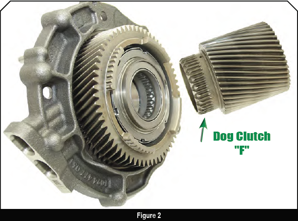
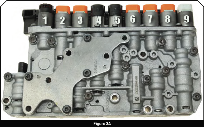
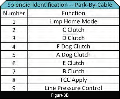
The F dog clutch is part of the driven gear support that is bolted to the case (figure 2), and is a holding/braking dog clutch. The valve body uses two on/off solenoids to apply and release these two dog clutches (figure 3).
Dog Clutch Hydraulics
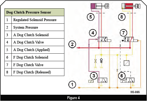
Both the A and F dog clutches use similar hydraulic circuits (figure 4). An on/off solenoid controls a switching valve that directs fluid to position the clutch valve.
The clutch valves are biased by the solenoid pressure circuit. This moves the valve all the way to the release position when the solenoid’s off.
The release circuits always have some pressure from the solenoid pressure circuit. This prevents shift delays resulting from drained clutch apply circuits.
B, C, D, and E Clutches
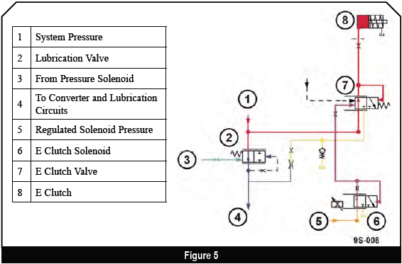
The B, C, D, and E clutches all have similar hydraulic circuits (figure 5). A pressure regulating solenoid and valve control a clutch valve. The clutch valve directs full system pressure to the clutch.
To release the clutch, the switching valve moves to connect the clutch apply circuit to the release circuit. The release circuit always has some pressure from the lubrication circuit. This prevents shift delays caused by drained clutch apply circuits. Some of the clutch valves have an additional circuit to support limp home mode or park-by-wire.
It’s important to recognize that the computer is constantly applying and releasing the clutches to synchronize the shift timing of the A and F dog clutches.

Unfortunately the clutch apply chart doesn’t include the “in-between” clutch applications (figure 6). Chrysler hasn’t identified which clutches are partially applied, yet. We’ll probably see that before too long, because it’ll be a critical diagnostic tool when it comes to diagnosing shift problems.
The Controls
Electronically controlled transmissions have been on the road for some time now and we’re all familiar with the controls or inputs that go to the TCM: the MAF, TPS, RPM sensor and so on.
The 948TE has all the usual inputs to the TCM for transmission control, plus a pressure transducer and the speed sensors; sensors that operate a bit differently than the ones you’re probably familiar with.
Pressure Transducer
The pressure transducer is mounted on the valve body. It monitors release pressure of both dog clutches. When one of the dog clutches releases, there’s a momentary increase in the dog clutch release circuit pressure. The Transmission Control Module (TCM) uses the signal from the sensor for control and diagnostics.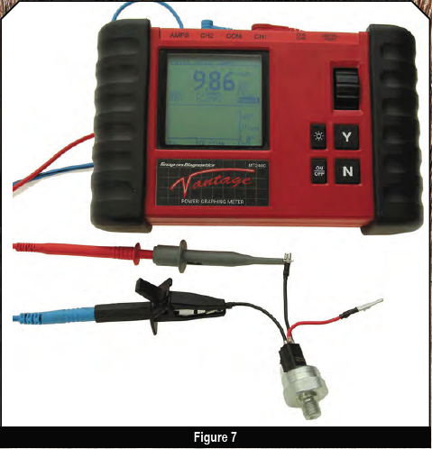
This pressure sensor is very different from pressure sensors of the past. It’s a 3-wire sensor like its predecessor, but that’s where the similarities end.
This transducer receives a 5-volt reference from the TCM, and it sends a variable voltage signal back to the TCM. The transducer is a modified piezoelectric (pronounced “pee-ay-zo” electric) pressure sensor.
According to the manufacturer, it has an integrated circuit board inside the sensor that receives the signal from the piezo crystal, and then it creates a signal to send to the TCM.
This means that you can’t test the sensor the normal way with an ohmmeter. The resistance across the terminals is extremely high (figure 7). If you look closely at the meter, it says 9.86 M ohms. That’s well over 9 million ohms resistance!
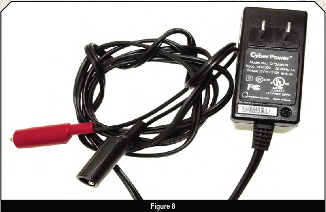
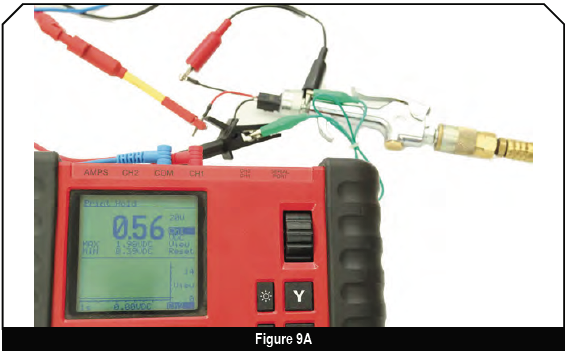
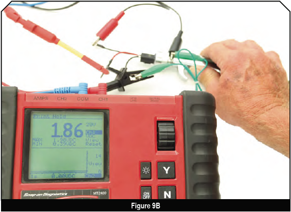
To bench test the transducer, you’ll need to power it up using a 5-volt power source (figure 8). Once the transducer is powered up, it’ll vary the voltage based on the pressure applied to it. The tested pressure transducer reads about half a volt with 0 PSI applied and 1.86V with about 110 PSI of shop air applied (figures 9A and B).
Speed Sensors
Because the dog clutches are coupled by interference instead of friction, the timing to engage and disengage them must be precise. The computer uses the speed sensors, engine RPM, and the pressure sensor to transition the dog clutches smoothly between engaged and disengaged. To do this, the TCM slips the remaining clutches, to make sure that the rest of the transmission components are spinning at the same speed.
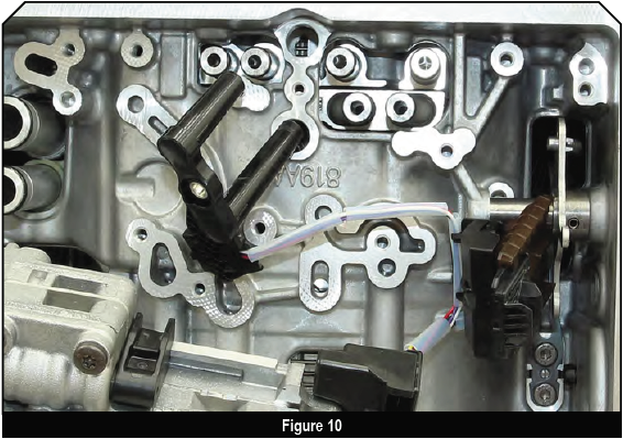
The speed sensors are two wire sensors that are built into a common housing (figure 10). They share a common ground. But these aren’t your typical, two-wire, pulse generator-type sensors.
These sensors receive a 9-volt reference signal from the TCM. The voltage energizes a chip inside the sensor, which then sends a signal to the TCM. This is called a magnetoresistive sensor. The advantage of this type of speed sensor is a cleaner signal at slower speeds.
For a complete explanation of the magneto-resistive speed sensor, check out Steve Bodofsky’s article in the July 2012 issue of GEARS.
The use of the A and F dog clutches is a new concept for us. It allows the transmission to be built in a smaller package, which saves weight… and we all know that’s about saving at the gas pump.
When you understand how the 948TE* works and what the TCM is using to control the shifts, the easier it’ll be to diagnose it. And when our jobs are easier, we all have Fun With Transmissions!
*Pick up the Chrysler 948TE Rebuild Procedures from our Bookstore today! Call 1-800-428-8489.


