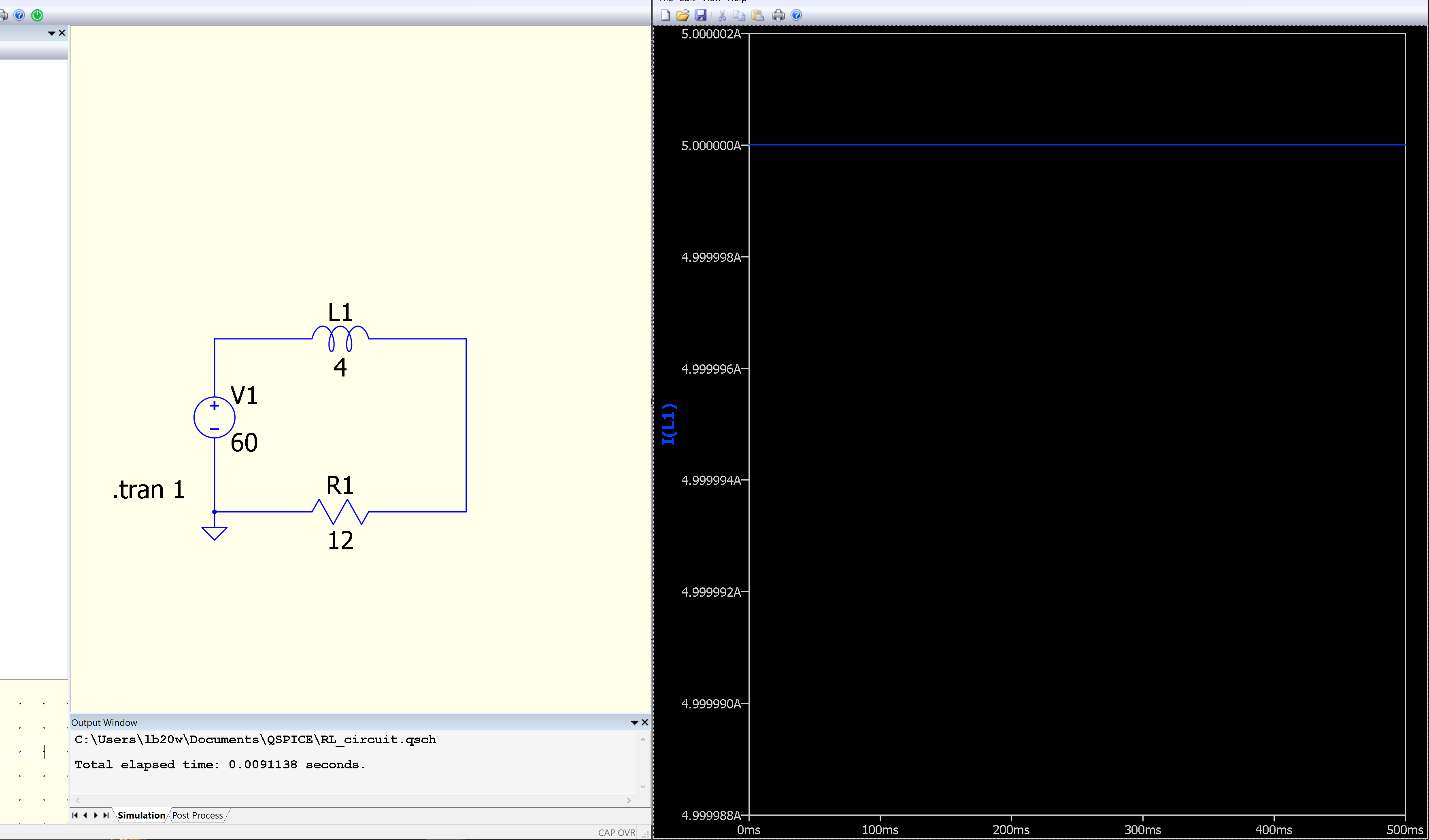
Hello. I’m new to qspice, and am using it for a project.
I’m trying to model the current as a function of time in an RL circuit, the instant a switch is closed (completing the circuit). Image 1 shows my attempts so far.
I have been able to produce a solution to the governing differential equation: I(t) = 5(1 - e^{-3t}). Which, when plotted, shows what I expect the graph to look like. Is there something I am overlooking in the qspice model that is causing the difference?
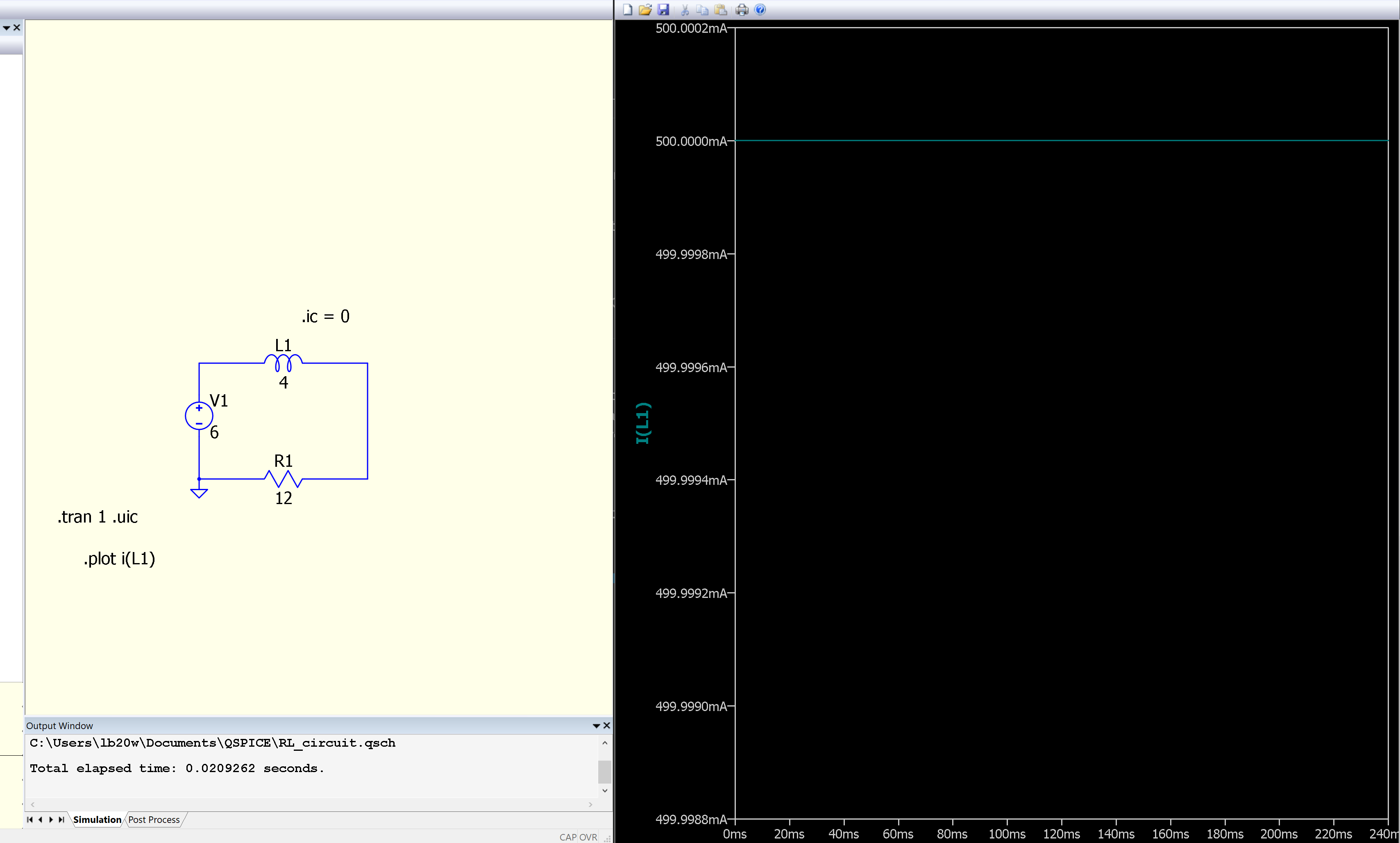
Thats caused by dc initial operating point solver. To avoid it, you can modify .tran 1 into .tran 1 .uic to force dc inititial operating point solver to not work.
Additionally you can .ic = 0 directive at the inductor to ensure inductor current starts from zero when the simulation starts
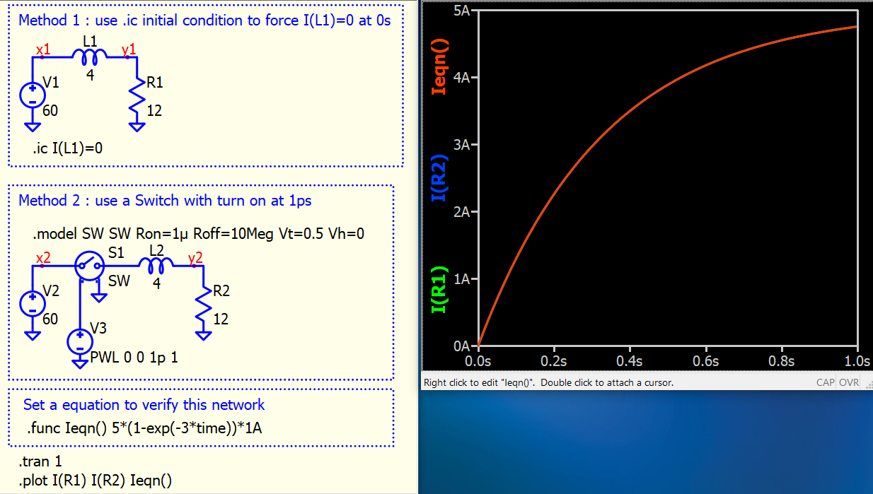
@physicboy already explained the critical part. Method 1 is .ic method in above. Or Method 2 with a switch. This example includes a .func to setup your formula, such that you can run simulation and compare with your math together. But three curves are overlapping in this plot. You have to click on its legend to force its on top.
You wrote wrong…its not .tran 1 .uic, but its only .tran 1 uic (without that dot in front of uic). Try this and you will see that the things will work and will be good
If you use .tran 1 uic, you don’t have to add .ic I(L1)=0, as uic force all initial condition to 0A/0V.
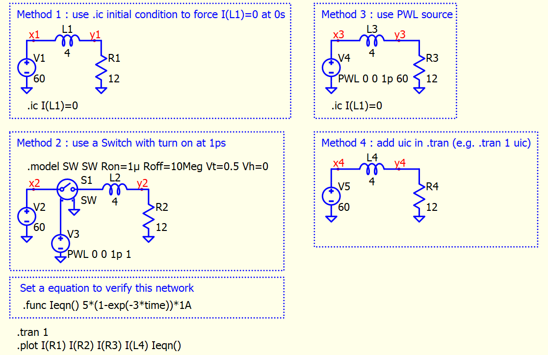
Actually, you have one more way, you can set your voltage source to PWL 0 0 1p 6, it will allow voltage start from 0V at 0s, which allow all initial condition to 0. No matter which method, idea is to have initial condition to 0V/0A. This is summary of 4 method. Method 4 needs to change .tran 1 to .tran 1 uic