Part 2 – Refrigeration System Controls
Refrigeration Controls
Refrigeration system loads vary from practically no load to the full design load. Necessary to equip the system with a number of automatic controls to ensure that the system operates within the desired limits.
Refrigeration controls can be divided into the classifications of operating or primary controls, actuating or secondary controls, and limiting and safety controls.
Activity: Refrigeration Control Classificiations
Operating Controls
The operation of a compressor (starting, stopping, and unloading) is usually done by:
- Temperature-actuated controls (thermostat)
- Pressure-actuated controls (pressurestat)
- Humidity-actuated controls (humidistat)
 |
 |
 |
| Thermostatic Control | Pressure Control | Humidity Control |
Temperature-Actuated Controls (Thermostat)
A direct type is the thermostat is located in the space to be cooled.
An indirect type has a fluid-filled bulb connected to a bellows or diaphragm by means of a tube or capillary. The bulb is located in the refrigerated space and the control is located outside in a convenient location.
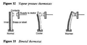
Thermostats may be operated by mechanical effects and electrical signals. Mechanical effect is the movement of a bimetallic element, expansion of a fluid (liquid or gas), and vapor pressure of a volatile fluid. An electrical signal is an electrical resistance and the electronic signals.
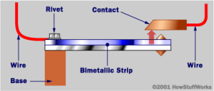
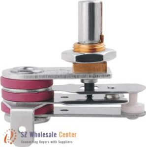
Bimetallic Thermostat
Principle: Different metals expand at different rates as they warm up – coefficient of expansion. And a strip is constructed of these two different metals – bimetallic strip.
Bimetallic element can be used to close or open an electrical circuit that:
- Starts or stops a compressor
- Opens or closes solenoid valves.
- Controls the power supply to small compressor motors
- Larger motors with a high current draw are indirectly controlled – the thermostat actuates a contactor to engage the starter switch.
- Compressor equipped with an unloader – the thermostat controls the operation of the unloader actuator.
 |
 |
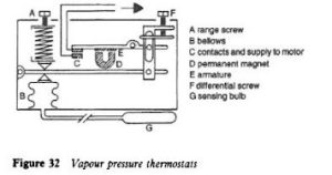
Fluid Expansion
A thermostatic controller filled with a fluid that responds to temperature fluctuations in the cooled medium. It contains a bulb, a tube, and a bellows filled with a liquid, a gas, or a saturated mixture of the two.
Activity: Thermostatic Controller Operation
Activity: Refrigeration Thermostatic Cycles
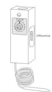
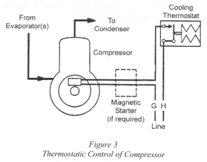
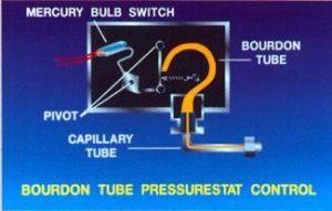
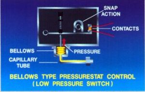
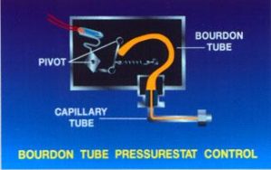
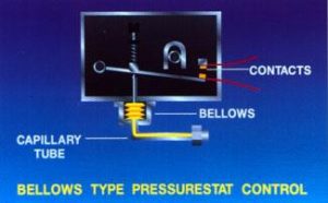
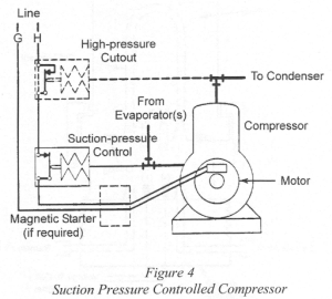
Pressure-Actuated Controls (Pressurestat)
Changes in the suction pressure of the compressor are directly related to changes in the temperature of refrigerant coming from the evaporator. Pressure-actuated control connected to the suction line of the compressor is used to start and stop the compressor. It is possible to maintain the evaporator temperature within close limits over varying load conditions.
Activity: Pressurestat Cycles & Controls
Activity: Maximum Air-Cooled Portable Chiller Reverse Flow Circuit Components
Pressure-actuated control is actuated through a linkage connected to a bellows or diaphragm – subject to the suction pressure of the compressor. This control acts in reverse to the thermostat; Opens the switch when the pressure drops to the cut-out setting and closes it when the pressure rises to a preset differential.
|
|
 |
 |
 |
A Pressure-actuated control cannot be used with an automatic expansion valve. The valve will maintain a constant evaporator pressure. With a capillary tube, the tube does not provide a tight seal between the high and low-pressure sides of the system when the compressor shuts down. This causes the pressures on both sides to equalize and the rising evaporator pressure would then restart the compressor almost immediately.
Humidity Acculated Controls (Humidistat)
Humidity-Actuated Controls (Humidistat) is a controller that measures and controls relative humidity. It may be used to control either humidifying or dehumidifying equipment by the regulation of electric or pneumatic switches, valves, or dampers.
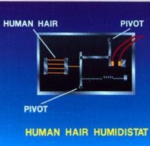
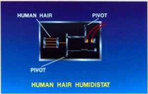
Electronic Humidistat
The sensing element consists of alternate metal conductors on a small flat plate. An increase or decrease in the relative humidity causes a decrease or increase in the electrical resistance between the two sets of conductors known as “hygroscopic” materials. Human hair and nylon are two examples of common hygroscopic materials. The Relay amplifier measures the change in resistance in the sensing element.
 |
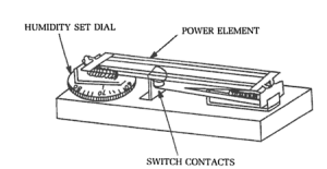 |
The power element is sensitive to humidity changes length in proportion to change in humidity and high humidity elongates the element, and closing switch contacts.
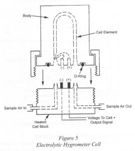
Electrolytic Hygrometer Cell
Electrolytic hygrometer cells consist of a chamber containing two electrodes supporting a thin layer of desiccant (drying agent) such as a hygroscopic salt. Moisture in the air is absorbed by this salt and when a constant low-power DC electric current is applied, the salt dissolved in the moisture breaks down into charged ions allowing the moisture to conduct an electric current. This reduced resistance to current flow results in a reduced voltage drop across the electrodes and this measured voltage, proportional to the moisture content, is then amplified for control purposes.
Actuating Controls
The main actuating controls include:
- Refrigerant flow controls (expansion valves)
- Solenoid valves
- Condenser cooling water regulating valves
- Evaporator pressure regulating valves
Refrigerant Flow Control (Expansion Valve): the expansion valve is one of the most important secondary controls in a refrigerating system.
Activity: Expansion Valves
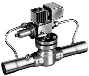
Solenoid Valves: Electromagnetically operated solenoid valve is used to stop the flow of liquid refrigerant to evaporators or the flow of cooling water to compressors and condensers.
Activity: Solenoid Valves
Activity: Solenoid Valves Energized & De-Energized
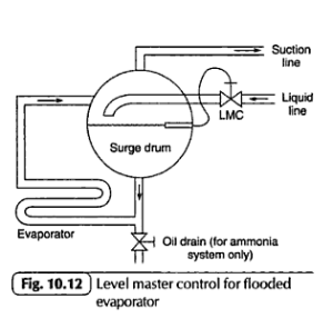
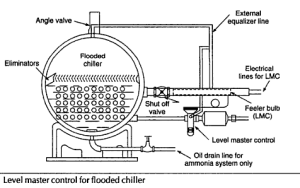
A multi-evaporator system is a separate solenoid valve used to control the flow of liquid refrigerant to each evaporator in a multi-evaporator system. The temperature of the section or zone served by each evaporator is controlled independently. The thermostat placed in that particular zone shuts off the solenoid valve and the solenoid valves are also used in conjunction with electric low-pressure float switches to maintain the level in flooded evaporators. In a multi-compressor system, the cooling water flow to each compressor is controlled by separate solenoid valves.
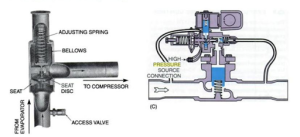
The condenser cooling water regulating valve automatically regulates the flow of cooling water to the condenser when the compressor is in operation, and shuts off the flow when the compressor stops. The valve is operated by the vapor pressure on the discharge side of the compressor. This pressure acts on the bellows and tends to open the valve against the spring force trying to close the valve.
Activity: Water Regulating Valves
A compressor not in operation has pressure on the high side that will not be high enough to overcome the spring tension that keeps the valve in the closed position. A compressor started will have high side pressure builds up and when it reaches the pressure at which the force on the bellows overcomes the spring tension, the valve opens, allowing cooling water to flow into the condenser to absorb heat from the vapor.
When condenser cooling load increases, the high side pressure rises, causing the valve to open wider to supply the increased amount of cooling water required. When the condenser cooling load decreases, The high side pressure drops and the valve automatically reduces the water flow. The pressure at which the condenser is maintained is set by adjusting the spring tension.
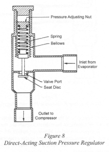
Evaporator pressure regulating valve has very low evaporator pressure resulting in low evaporator temperature, which causes frosting of coils or freeze-ups in water chillers. The evaporator pressure regulator prevents an overly low pressure and low-temperature condition from occurring in the evaporator while the compressor is running. It is installed at the evaporator outlet.
 |
 |
Direct-acting evaporator pressure regulator‘s pressure in the evaporator increases and pressure under the seat disk increases and acts indirectly on the bellows, through the valve stem, to overcome the spring force and increase the valve opening. When the pressure in the evaporator decreases, the spring force throttles the valve further and reduces the flow of refrigerant. When the temperature is sufficiently lowered, the thermostat or humidistat signals for the closure of the solenoid valve upstream from the expansion valve. Before the compressor can shut down, it must pump out the remaining refrigerant in the evaporator, and failure to do this could result in liquid slugging or, sometimes, a high suction pressure when the compressor is eventually restarted. The evaporator pressure regulator will automatically limit the degree of pump-down. In order to circumvent this situation, a bypass valve is installed around the evaporator pressure regulator. When the solenoid valve closes, the bypass valve opens and remains open until the pump out is complete and the compressor shuts off. Then the bypass valve closes. A direct-acting evaporator pressure regulator that is installed in the outlet of each of the evaporators maintains different evaporator temperatures in these coils and the compressor suction pressure is set to maintain the pressure of the evaporator with the lowest temperature.
Direct-acting evaporator pressure regulator’s suction pressure regulating valve is installed before the compressor and limits the suction pressure at the compressor inlet to a preset maximum if the pressure in the evaporator rises to a high value. It protects the compressor from overload when the evaporator pressure rises above normal pressure.
Limiting and Safety Controls
Guards against any abnormal conditions in a system will stop operation if either a pressure or a temperature becomes excessively low or high, protect the compressor against oil pressure and temperature problems, and protect the motor against high temperature and overload. The flow switches on chilled water and cooling water lines and air ducts.
Pressure limits and high-pressure safety cut-out means the condenser pressure may become higher than normal due to insufficient cooling of the high-pressure vapor in the condenser or the presence of non-condensibles in the system.

Low-pressure cut-off is a pressure-operated safety switch used to protect the system against a lower-than-normal suction pressure. Low-pressure cut-off operates on the same principle as the high-pressure safety cut-out and when a low-pressure cut-off is used, it is usually combined with a high-pressure cut-out. Low suction pressure occurs when the pressure-actuated operating control fails to stop the compressor at its cut-out pressure.
With temperature limits, low limit thermostat is identical to a compressor control thermostat and is used in systems where a drop in temperature below the minimum setting of the operating thermostat could result in damage to the equipment.
It is important that the water in water chilling systems is never allowed to freeze since this could cause extensive damage to the chiller to prevent freezing, the sensing element of a low-limit thermostat is immersed in the water at the coldest point in the chiller. It trips the compressor at a low temperature.
Chilled water, low-temperature cut-out, and recycle switch uses a thermostat to sense the chilled water temperature leaving the chiller. If the temperature drops approximately 2°C – 3°C below the setpoint of the control thermostat, it shuts down the compressor. When the water temperature rises approximately 5°C – 6°C again, the thermostat restarts the compressor.
A chilled water flow switch is installed in the chilled water exit line, this switch protects the chiller from freezing due to lack of water flow and opens the compressor motor circuit when water flow drops below the safe minimum flow.
 |
 |
Compressor protection equipment is a compressor equipped with an oil pressure failure switch. It shuts the compressor down when oil pressure drops below a safe minimum limit or the lubrication system fails. Oil pressure should be measured as the pressure difference between oil pump discharge pressure and suction pressure. An oil pressure failure switch has two opposed pressure bellows which operate a timed switch controlling the power supply to the compressor motor. If the oil pressure is at the set parameter, the timed switch is kept in the closed position allowing operation of the compressor.
The compressor starts when the differential pressure switch and the timer switch are closed – time delay allows the compressor to operate for about two minutes until oil pressure rises. If the pressure differential is not established within the preset time, the compressor motor shuts off.
Activity: Oil Pressure Failure Switch
High oil temperature cut-out shuts down a compressor when the lubricating oil temperature becomes too high due to loss of water in the oil cooler and bearing failure causes excessive heat generation. It opens a relay in the motor starting circuit, stopping the motor when the oil temperature exceeds safe limits. Low oil sump temperature protection prevents a compressor from startup if the oil heater fails to heat the lubricating oil to a preset temperature so that the refrigerant dissolved in the oil separates from the lubricant.
A centrifugal compressor vane closed switch is closed when the guide vanes of a centrifugal compressor are in the closed position, allowing the compressor to be started only under no-load conditions.
Motor Protection
High motor temperature cut-out stops the motor under high-temperature conditions.
Motor overload protection is one type that uses a current transformer with a resistor in the motor circuit. An increase in current flow causes a greater voltage drop across a resistor in the electrical circuit. A change in voltage is amplified by an electronic circuit to operate relays. Motor overload protection controls the refrigeration system or closes the inlet vanes at the centrifugal compressor inlet. If the vane control should fail, the relay operates solenoid valves to force the hydraulic motor on the vanes into the closed position by applying oil or air pressure to one side of the piston and bleeding the other side.
Flow Protection
Flow switches are used on chilled water and cooling water lines and air ducts. a flow switch is used as a safety lockout switch for the refrigerating system should the flow in these lines or ducts slow or stop. flow switches are also used to close flow indicator circuits. The switch is operated by the force exerted on a flexible vane immersed in the liquid flowing through the line.
Pressure Relief Devices
A refrigeration system is a closed-pressure system with the potential for pressure in the system or in its components may build up excessively due to extreme temperature conditions, malfunctioning controls, and inadvertently closed stop valves. The most common pressure relief devices used in refrigeration systems are spring-loaded relief valves, fusible plugs, and rupture discs.
The spring-loaded relief valve, this relief valve is a spring-loaded valve, set to open and discharge refrigerant if pressure exceeds the set value and the spring-loaded safety valve has the advantage of resealing itself, or closing, when the pressure drops to a safe limit.
Activity: Spring-loaded Relief Valves
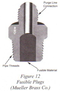
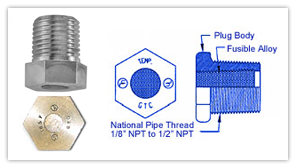
A fusible plug is a connection that is filled with a metal alloy designed to melt at a specific temperature. The plug melts when the rated temperature of the relief device is reached, allowing the entire refrigerant charge to escape. A new plug and new refrigerant charge will be required. A fusible plug is commonly used in smaller systems as the loss of the refrigerant in large systems is quite costly. The use of spring-loaded relief valves is more economical and more practical in such systems.
 |
 |
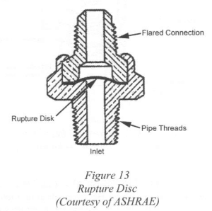
Rupture discs are similar to a fusible plug, but they have a thin metal disc inside which bursts before the pressure in the system reaches dangerous levels and is threaded into the liquid receiver. Rupture discs are connected to a purge line to carry away the released refrigerant. All rupture members used in lieu of or in series with a relief valve shall have a nominal rated rupture pressure not exceeding the design pressure of the protected parts of the system.
 |
 |