The inception of G-code programming finds its roots in the monumental advancements of the mid-20th century, closely intertwined with the evolution of computer programming languages. In 1957, John Backus crafted Fortran, a pioneering programming language tailored for statistical and mathematical computations, marking a significant milestone in the history of coding. Notably, Fortran stands as one of the oldest programming languages still in use today, underscoring its enduring significance in the technological landscape.
A mere year later, in 1958, the first iteration of G-Code, known as RS-274, emerged, marking a pivotal moment in the annals of programming history. Functioning as one of the earliest programming languages that persists to this day, G-Code has witnessed an exponential surge in its application, particularly in the contemporary realms of 3D printing and Computer Numerical Control (CNC) machines. Its emergence was contemporaneous with the development of various other early high-level programming languages, cementing its position as a foundational pillar in the domain of computer programming.
Presently, the standard version of G-Code, known as RS-274D (ISO 6983), serves as the cornerstone for the controls integrated into new machinery by tooling manufacturers. While adhering to this standardized framework, manufacturers augment the G-Code with tailored features, customizing it to accommodate specific requirements. As such, familiarity with the nuances of these custom features is imperative, underlining the necessity for practitioners to consult operators’ manuals to comprehend the modifications appended to the standard G-Code framework.
A crucial aspect that underscores the contemporary relevance of G-Code is its seamless integration with Computer-Aided Design and Computer-Aided Manufacturing (CAD/CAM) software. This integration facilitates the output of G-Code files through a post-processor, aligning the code with the specifications of the intended machine, thus streamlining the manufacturing process.
The origin of G-Code, however, predates the prevalence of sophisticated Computer Numerical Control (CNC) machines. Initially conceptualized at the Massachusetts Institute of Technology (MIT) for 2-axis plotters, G-Code has since evolved to accommodate the complexities of modern 12-axis machining centers. This evolutionary trajectory reflects the adaptability of the language to the growing demands of the industrial landscape, with advancements such as the integration of Macro programming solidifying its position as a versatile and dynamic tool.
The introduction of Macro programming in modern G-Code has ushered in a new era of versatility and functionality. Equipped with the capacity for variables, logical statements, and mathematical operations, G-Code has transcended its conventional parameters, incorporating features akin to traditional programming languages. While limitations persist, such as the incapacity to handle strings and arrays, the inclusion of variable storage and utilization has rendered G-Code an engaging and powerful language, enabling the creation of customized cycles and expediting manual coding processes.
Despite its six-decade-long existence, G-Code continues to undergo evolution and updates to align with contemporary industrial requirements. This perpetual adaptation reaffirms the enduring relevance of G-Code in the realm of manufacturing, underscoring the significance of possessing proficiency in G-Code programming as an invaluable asset within the machine shop environment.
Quick Guide to the Basic G Codes:
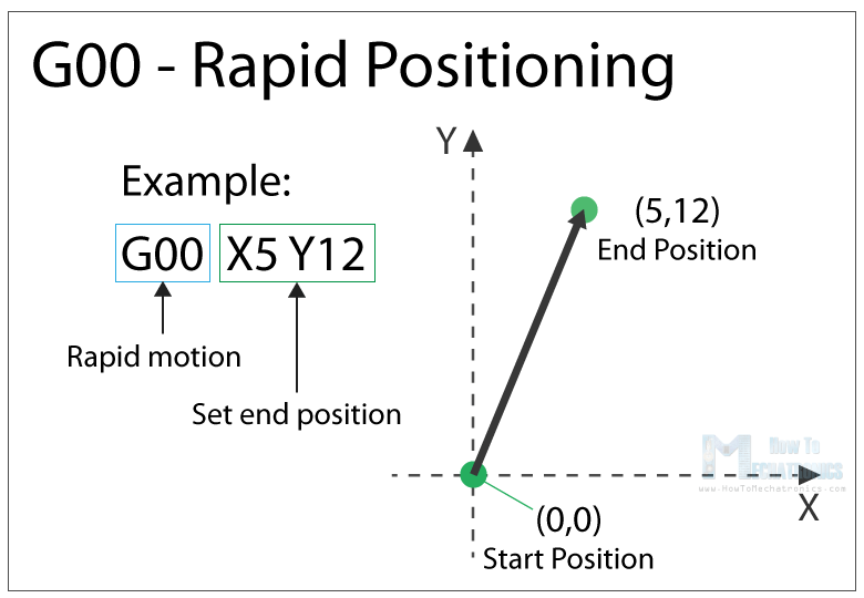
G00 – Rapid Positioning
The G00 command moves the machine at maximum travel speed from a current position to a specified point or the coordinates specified by the command. The machine will move all axis at the same time so they complete the travel simultaneously. This results in a straight line movement to the new position point.
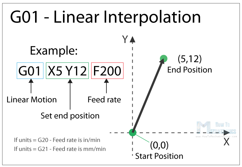
G01 – Linear Interpolation
The G01 G-code command instructs the machine to move in a straight line at a set feed rate or speed. We specify the end position with the X, Y and Z values, and the speed with the F value.
The machine controller calculates (interpolates) the intermediate points to pass through to get that straight line. Although these G-code commands are simple and quite intuitive to understand, behind them, the machine controller performs thousands of calculations per second in order to make these movements.
Unlike the G00 command which is used just for positioning, the G01 command is used when the machine is performing its main job. In case of lathe or mill, cutting material in straight line, and in case of a 3D printer, extruding material in straight line.
G02 – Circular Interpolation Clockwise
The G02 command tells the machine to move clockwise in a circular pattern. It’s the same concept as the G01 command and it’s used when performing the appropriate machining process. In addition to the end point parameters, here we also need to define the center of rotation, or the distance of the arc start point from the center point of the arc. The start point is actually the end point from the previous command or the current point.
For better understanding, we will add the G02 command after the G01 command from the previous example.
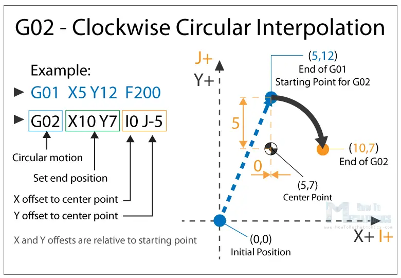
So, in the example first we have the G01 command which moves the machine to the X5, Y12 point. Now this will be the starting point for the G02 command. With the X and Y parameters of the G02 command we set the end point. Now in order to get to this end point using a circular motion or using an arc, we need to define its center point. We do that using the I and J parameters. The values of the I and J are relative to the starting point, or the end point of the previous command. So, to get the center point to the X5 and Y7, we need to make an offset of 0 along the X axis, and offset of -5 along the Y axis.
Of course, we can set the center point anywhere else, thus we will get a different arc which ends at the same end point. Here’s an example of that:
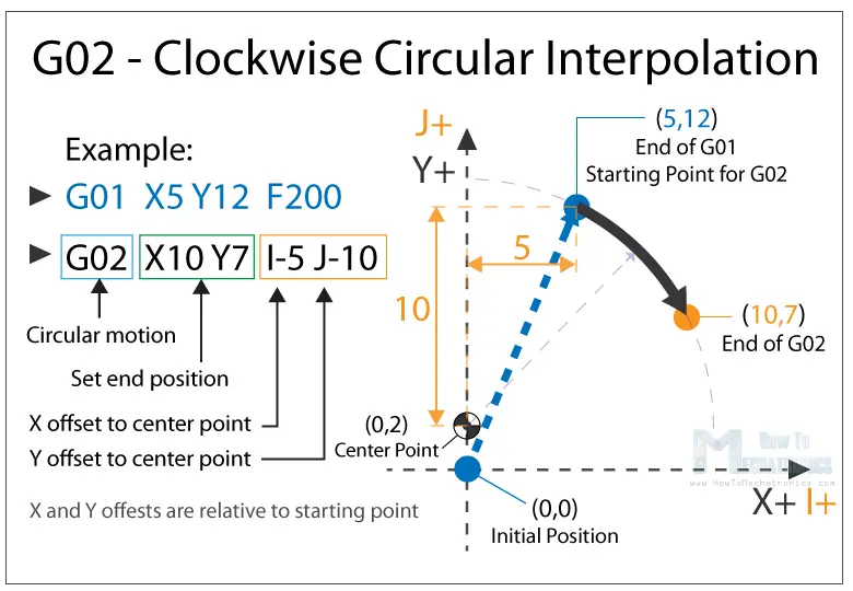
So, here we still have the same end point as the previous example (X10, Y7), but the center point is now at different position (X0, Y2). With this we got wider arc compared to the previous one.
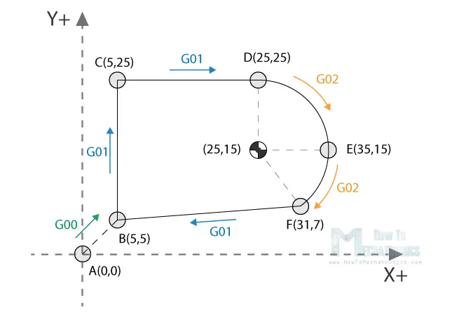
G00, G01, G02 Example – Manual G-code Programming
Let’s take a look at a simple CNC milling example using these three main G-code commands, G00, G01 and G02.
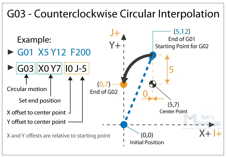
G03 – Circular Interpolation Counterclockwise
Just like the G02, the G03 G-code command defines the machine to move in circular pattern. The only difference here is that the motion is counterclockwise. All other features and rules are the same as the G02 command.
So, with these three main G-code commands, G01, G02 and G03 we can generate a toolpath for, literally, any shape we want. You might be wondering now how is that possible, but that’s actually an easy task for a computer and a CAM software. Yes, it’s true we can sometimes manually make a G-code program, but most of the time we do that with appropriate software which far more easier and safer.
G20/ G21 – Units Selection
The G20 and G21 commands define the G-code units, either inches or millimters.
- G20 = inches
- G21 = millimiters
We need to note that the units must be set at the beginning of the program. If we don’t specify the units the machine will consider the default set by the previous program.
G17/ G18/ G18 – G-code Plane Selection
With these G-code commands we select the working plane of the machine.
- G17 – XY plane
- G18 – XZ plane
- G19 – YZ plane
The G17 is default for most CNC machines, but the other two can be also used for achieving specific movements.
G28 – Return Home
The G28 command tells the machine to move the tool to its reference point or home position. In order to avoid collision, we can include an intermediate point with X, Y and Z parameters. The tool will pass through that point before going to the reference point. G28 X## Y## Z##
The home position can be defined with the command G28.1 X## Y## Z##.
G90/ G91 – Positioning G-code commands
With the G90 and G91 commands we tell the machine how to interpret the coordinates. G90 is for absolute mode and G91 is for relative mode.
In absolute mode the positioning of the tool is always from the absolute point or zero. So the command G01 X10 Y5 will take the tool to that exact point (10,5), no matter the previous position.
On the other hand, in relative mode, the positioning of the tool is relative to the last point. So if the machine is currently at point(10,10), the command G01 X10 Y5 will take the tool to point (20,15). This mode is also called “incremental mode”.
More Commands and Rules
So, the G-code commands we explained above are the most common ones but there are many more. There are commands like cutter compensation, scaling, work coordinate systems, dwell etc.
In addition to the G-code, there also M-code commands which are used when generating a real full-fledged G-code program. Here are few common M-code commands:
- M00 – Program stop
- M02 – End of program
- M03 – Spindle ON – clockwise
- M04 – Spindle ON – counterclockwise
- M05 – Spindle stop
- M06 – Tool change
- M08 – Flood colant ON
- M09 – Flood colant OFF
- M30 – End of program
In case of a 3D printer:
- M104 – Start extruder heating
- M109 – Wait until extruder reaches T0
- M140 – Start bed heating
- M190 – Wait until bed reaches T0
- M106 – Set fan speed
Some of these commands need appropriate parameters. For example, when turning on the spindle with M03, we can set the spindle speed using the S parameter. So, the line M30 S1000 will turn on the spindle at speed of 1000 RPM.
We can also note that many codes are modal, which means they remain in effect until cancelled or replaced by another code. For example, say we have a code for linear cutting movement G01 X5 Y7 F200. If the next movement is again a linear cutting, we can just type the X and Y coordinates, without the writing G01 at the front.
Thanks to howtomechatronics.com for this brief summary on basic G-Codes