Lead Screw: The Simple Mechanism that Demands Basic Knowledge
What are the basic parameters for the lead screw and nut? What are the optional lead screw manufacturing processes? How to inspect the lead screw and with what metrics? These are the questions you may have when starting to design a lead screw transmission.
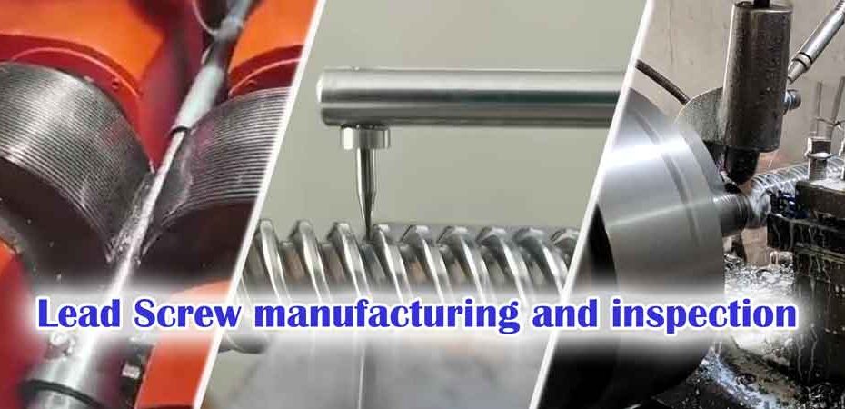
The lead screw is a simple but precise mechanism that turns rotary motion into linear motion. They look quite simple. However, it is still important to understand the basic knowledge behind them. In this post, we are going to introduce the basic concepts of lead screws and nuts, different machining processes, the metrics used to measure the quality of the lead screws, and how to inspect them.
Table of contents
Lead screw vs. ball screw
Let’s start by comparing the lead screws and ball screws. The lead screw has direct contact with the nut and generates sliding friction. While for the ball screws, there are rollers between the screws and nuts, so it is the rolling friction between the moving components.
For this reason, the roller screw has lower friction and higher transmission efficiency and is more suitable for high-speed transmissions.
The advantages of the lead screws are:
- Many lead screws are self-locked, meaning the linear motion can not be converted into rational motion. Sometimes self-locking is required in its application.
- The lead screws are simpler in structure, more compact in size, and lower in costs.
- They are more suitable for high torque transmissions.
The lead screws are widely used in vises, jacks, presses, and linear actuators.
Types of thread for lead screws
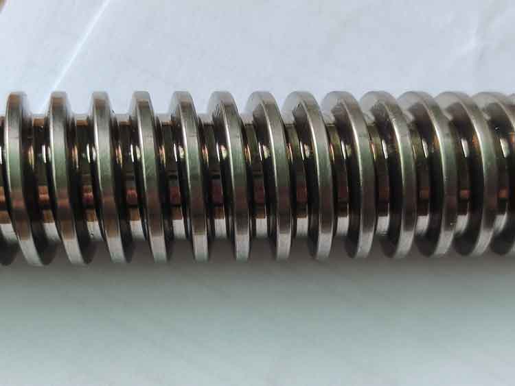
The lead screws usually have larger and flatter teeth than other screws, which allows them to be stronger to transmit torque or power. Based on different thread geometries, the lead screws are classified as
- ACME thread: It has a similar geometer as the trapezoidal thread, except it has a 29°thread angle, and they come in inches.
- ISO metric trapezoidal thread: It has a 30°thread angle, and the dimensions are in millimeters.
- Square thread: The flanks of the thread are vertical to its axis. It is normally used for transmission of high axial load. The jacks, and vises all use square threads.
- Buttress thread: one flank is flatter than the other side. it is normally used for one-direction axial load.
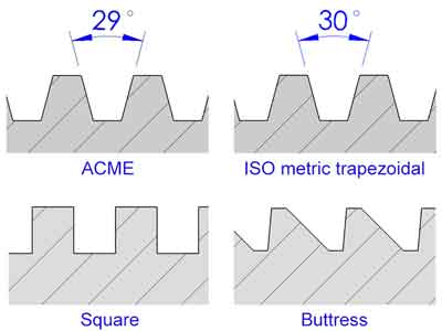
Among them, the trapezoidal or acme threads are most commonly used due to their manufacturability, achievable precision, self-centering property, transmission efficiency, and strength of thread roots.
Basic terms for lead screws
We have concluded the basic terms for the lead screws as follows. We put the terms in pairs (for the External and Internal threads respectively) for easier understanding.
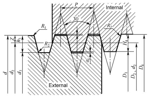
- Major diameter (d for External, D4 for Internal): The largest diameter of a thread. It is the crest of an external thread or the bottom of an internal thread.
- Pitch diameter (d2 for External, D2 for Internal): A hypothetical cylinder where the teeth thickness equals the space. Pitch diameter is critical for the performance of lead screws.
- Minor diameter (d3 for External, D1 for Internal): the smallest diameter of a thread. It is the crest of an internal thread or the bottom of an external thread.
- Pitch (P): the distance between 2 neighboring teeth.
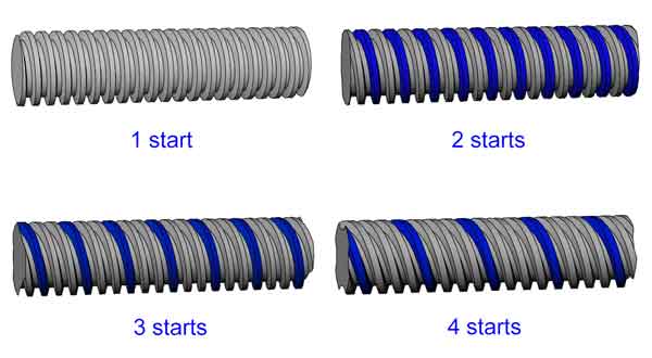
- Screw starts: the number of independent threads that a screw has.
- Lead (L): The distance the thread advances in one revolution. It equals the Pitch multiply number of screw starts.
Designation of lead screws
With what has been explained above, here is an example of a lead screw:
Tr 16*8 (P4) 7H/7e
- Tr—This means ISO metric trapezoidal thread
- 16—Major diameter of both the internal screw (nut) and external screw (bar) are 18 mm.
- 8—The lead of the screw is 8 mm.
- P4—The pitch is 4 mm, which also means this screw has 2 starts (2*4 mm=8 mm)
- 7H—The tolerance for the pitch diameter of the nut is 7H.
- 7e—The tolerance for the pitch diameter of the rod is 7e.
Tolerances for trapezoidal screws
Unlike the IT grades (IT represents International Tolerance) which is widely used for general machining tolerancing, the lead screws have a different system for defining their dimensional tolerances. The reference standards are as follows:
- ISO 2901 : 1993, ISO Metric Trapezoidal Screw Threads – Basic Profile and Maximum Material Profile
- ISO 2902 : 1977, ISO Metric Trapezoidal Screw Threads – General Plan
- ISO 2903 : 1993, ISO Metric Trapezoidal Screw Threads – Tolerances
- ISO 2904: 1977, ISO Metric Trapezoidal Screw Threads – Basic dimensions
Tip:
Don’t get confused with the IT grade tolerance that is most used in other engineering areas.
For example, with IT grade, the Φ22 H7/js6 actually means:
- Φ22 H7—Φ22 +0.021/0 for the hole;
- Φ22 js7—Φ22 +/-0.065 for the rod.
While with lead screws, the Tr22*5 7H*7e means:
- 7H—19.500~19.875 for D2 (the pitch diameter for the nut);
- 7e—19.114~19.394 for d2 (the pitch diameter for the rod).
The 7H and 7e refer to the tolerance bands for the pitch diameter only (7H for the inner thread D2 and 7e for the outer thread d2). The tolerances for the major and minor diameters are defined in other ways. Let’s break it down here:Ti
- The major diameter of the external thread (d)—always 4h
- The minor diameter of the internal thread (D1)—always 4H
- Pitch diameter for external (d2) and Internal threads (D2)—there are several options.
Recommended tolerance classes for pitch diameter:
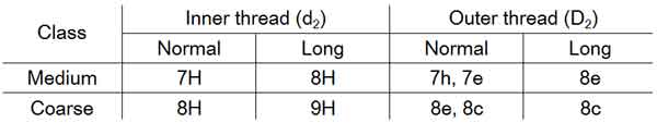
Here the “Normal” and “Long” refer to the length of engagement.
“Medium” can be chosen for the usual application. When machining difficulty exists or for lower transmission requirements, “coarse” can be selected.
Major diameter for Internal screw (D4)—only minimum dimension is defined. This is probably because the D4 is less important. Meanwhile, since internal threads (on the nut) are usually cut by a CNC machine, the geometry of the teeth profile is decided by the shape of the cutter, so the D4 can not be too large without a limit.
- Minor diameter for the external screw (d3)—it will be the same grade of the pitch diameter d2, but the tolerance band will be “h”. For example, if the d2 is 8e, then the d3 should be 8h.
For each specific trapezoidal thread, there is an online calculator that you can easier get their tolerances.
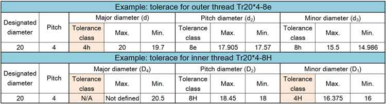
An example: the tolerance for a mating screw and nut, Tr20*4-8H*8e (8H for the inner thread and 8e for the outer thread)
An example: the tolerance for a mating screw and nut, Tr20*4-8H*8e (8H for the inner thread and 8e for the outer thread)
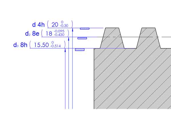
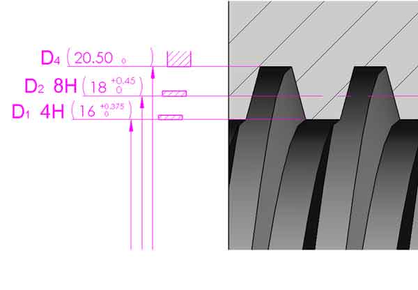
Now, if we put the tolerance bands for the outer and inner screws together, they will look like this:
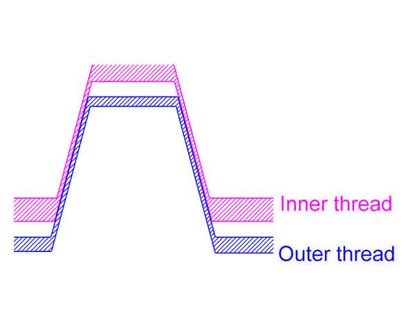
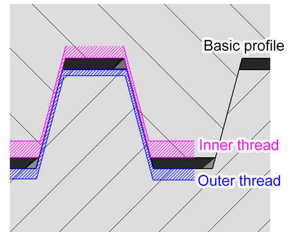
From the above images, we can conclude that:
- There are clearances between the screw bar and the nut on the major diameter, minor diameter, and pitch diameter (or the flanks);
- The clearance between the flanks is the smallest. It will be the flanks that are in contact when the screw bar is assembled with the nut. This also means the pitch diameter and the flank angles are the most critical metrics for the proper performance of lead screws and nuts.
Lead accuracy and straightness
Lead accuracy: The lead accuracy or lead deviation means the difference between the actual linear distance and the theoretical linear distance the helix (or the screw) travels. It is usually described by deviation per meet or foot. For example: 1.2mm/meter or 0.01″/foot. Obviously, the better lead accuracy, the more precise linear motion you will get from the lead screw.
Lead screw straightness: Because most lead screws are thin and long pieces, it is inevitable that they will be slightly bent. In the manufacturing of lead screws, the tolerance of straightness needs to be specified. It is also given as the deviation per unit length (or the total part length). For example: 1.5mm/meter, 0.005″/foot, or 1.2mm on the total part length.
The bend of the finished screw bars comes partly from the raw steel bars, and partly from the machining process itself. In order to improve the straightness of the lead screws, it is recommended to straighten both the raw steel bars and finished lead screws. Usually, straightness of 0.15-0.3mm per meter can be obtained for most machining processes.
The raw steel bars supplied in good condition can be machined without pre-straightening, this will save a lot of costs. It is important to source the steel bars from a good supplier.
When the steel bars are too bent, like over 1 mm/meter, it will cause excessive stress and heat in the screw rolling process, and may cause surface flaws like grooves and peels.
Manufacturing methods for lead screws
1. Screw rolling
Screw rolling is a cold-forming process that which 2 rollers (or sometimes 3 rollers) squeeze the bar stock to form the threads. It is the most popular manufacturing method for lead screws.
In the screw rolling process, the major diameter of the screw will be squeezed larger than the diameter of the bar stock (while the minor diameter will become smaller), it is critical that the diameter of the bar stock is precise and falls in the required tolerance.
Advantages:
- High efficiency and low price. The screw teeth are usually formed by one pass, or sometimes two passes, so the productivity is by far ahead of any other manufacturing processes.
- The surface is quite smooth, and it is hardened in the cold forming process. The grains of its microstructure is kept intact (while the turning or milling will cut off the grains), so the rolled threads are harder, stronger, and they have better impact and wear resistance.
- The roller dies are endurable. They are usually good for thousands of pieces of manufacturing, which also lower the per piece manufacturing cost.
Disadvantage:
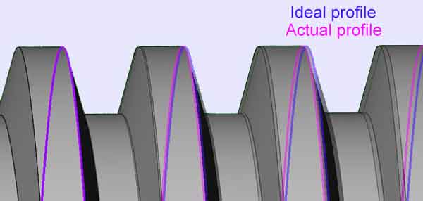
1. The lead accuracy is poorer than other machining processes but still good for many applications.
Unlike turning or whirling, in thread rolling, the workpiece is actually being pushed forward freely by the rolling of helical lines of the roller dies, the feeding of the workpiece is less accurate. At the same time, the squeezing will cause some slight longitudinal deformation. Even if each pitch is 0.1% off the normal (like 0.004mm on a 4mm pitch), which does not seem a lot, it may translate into a 1mm deviation on a 1-meter span.
2. Screw rolling can only be used for large quantity production. Due to the higher initial tooling cost and the bar stock need to be precise in the diameter. For this reason, it is recommended to use the sizes of threads that the manufacturer is currently producing.
3. The shoulders on the 2 ends (for mounting and connection to the driven shaft) should be smaller than the minor diameter of the screw. Otherwise, there will be grooves left after machining of the 2 ends
Turning
Turing is the most traditional yet effective manufacturing method for lead screws. it uses a formed cutting tool that has the shape of the thread teeth to cut the threads.
There is no limitation on the size of the shoulders. When they are larger than the minor screw of the screw, it is recommended to use turning or other processes to produce the lead screw.
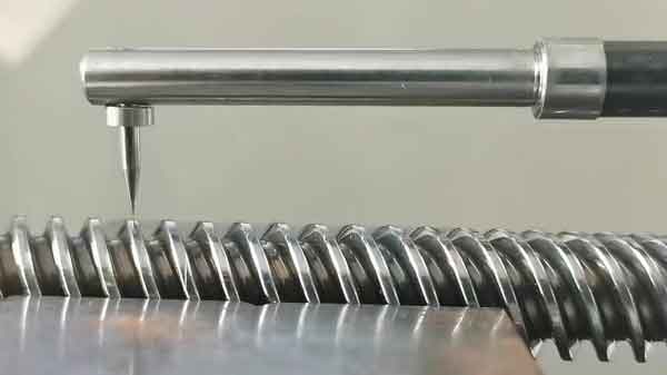
Thread whirling (planetary thread milling)
Like the turning process, thread whirling is another metal removal process. The whirling ring has multiple cutting tips mounted on the internal diameter, it rotates at a high speed and cuts the threads on the stock bar (the workpiece) which rotates and moves forward (feeding) at a much slower speed. The workpiece moves forward at the distance of LEAD with each revolution.
Inspection methods for lead screws and nuts
Obviously, we can use a caliper or micrometer to check the outer diameter of the screw bars (d) or the inner diameter of the nuts (D1), but that is certainly not enough. Here are the inspection devices and inspection methods to check the lead screws and nuts:
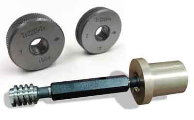
Go-No go gauges
The go-no go gauges can be used for checking the pitch diameters (d2 and D2) of both the screw bars and nuts. They are easy and quick to use.
However, we can not get a quantitative result with go-no go gauges, so we will not know whether the dimensions fall in the optimized zone. Meanwhile, in practice, sometimes both d2 and D2 can be both made larger or smaller so they still match well together. When this is the case, the go-no go gauge will not be very useful.
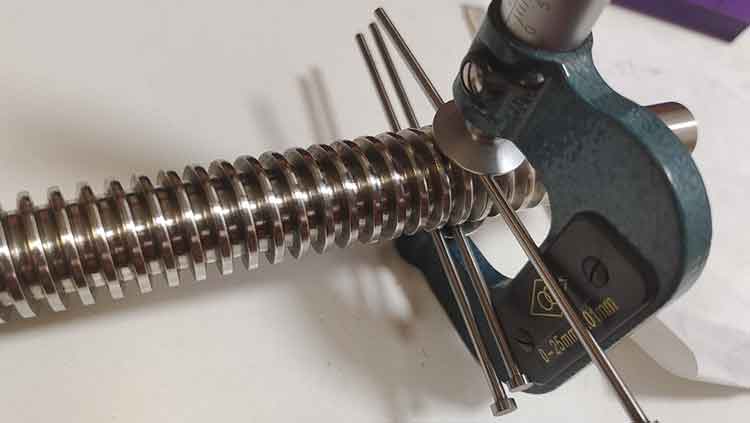
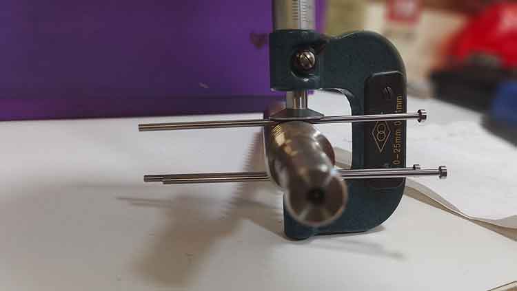
3 wire method for measuring pitch diameter
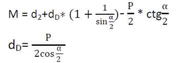
The 3-wire method is the contact type measurement method (meaning the measuring device has direct contact with the object to be measured) to check the pitch diameter of screws. It uses a disc micrometer and 3 wires (or called pins) to do the measurement. These 3 wires must have the exact same diameter. 2 wires are put on one side of the screw, and the other wire will be placed on the other side. Using the disc micrometer to check the M value, the pitch diameter can be derived from the following formulas:
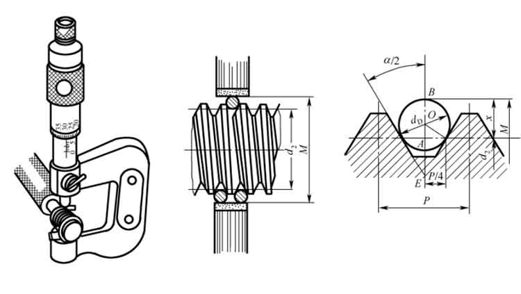
- α: the flank angle,
- P: pitch
- d2 : pitch diameter of the outer thread
- dD:: diameter of the wire
Please note dD does not have to be the exact value calculated by this formula as long as they are close enough, and again these 3 wires need to be precisely the same diameter.
When we calculate the value by putting in the flank angle (α)with specific numbers (60°, 30° and 29°), the formulas can be simplified as follows:
| flank angle (α) | Formula | |
| 60° (not usual) | M=d2+3dD-0.866P | dD=0.577P |
| 30° (ISO metric) | M=d2+4.864dD-1.886P | dD=0.518P |
| 29° (ACME) | M=d2+4.994dD-1.933P | dD=0.516P |
Here is an example for calculating the measurement for Tr22*5:
The diameter of the wire (dD) should be 0.518*5=2.59 mm, but we can use the Ø2.5 mm wires instead.
Since M=d2+4.864dD-1.886P, then d2=M-4.864dD+1.886P.
When the reading of M=22.05, then d2=19.22.
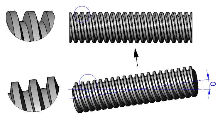
Screw profile projector (also known as optical comparator)
This is a non-contact inspection instrument, it can not be used to check inner screws. It projects the screw profile to the screen with a much-enlarged image, so you can look at the surface finish closely and check if there are any flaws like scratches, peels, etc. You can also measure the outer, pitch, and inner diameter, flank angle of an outer screw, but you need to capture the profile point by point manually, so the process is quite time-consuming, and sometimes not as accurate if not operated properly.
In order for the teeth profile to be projected correctly, the lead screw must be tilted by the helix angle (θ) so the teeth will face the camera lens vertically. Because of that, the screw profile projector is a bit different than others in that the head of the projector can be rotated to the desired angle to the worktable.
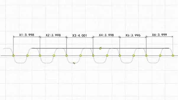
Profilometer
The profilometer can be used to check the surface roughness, and it can also be used to check surface profiles.
It has a diamond tip that moves up and down along with the profile when the sample screw moves horizontally. It records its journey with precise 2-dimensional data. These data can be graphed as well to visualize the measurement result.
In the shop practice, the clearances between the outer and inner threads are often made slightly larger than the ISO standards. This means the pitch diameter d2 can be smaller and D2 can be larger. Besides, the OD of the threaded bars (d) and the ID the nuts (D4) can be off the tolerances a bit. After all, the pitch diameters are more critical for their performance. It all depends how the they perform in their actual application in terms of accuracy and operating life. You need to keep the balance between the manufacturing cost and quality, but not be restricted to the standards.
There are different kinds of lead screw manufacturers on the market, some of them have cutting-edge manufacturing and inspection equipment and are well managed, while others are small workshops, but their prices are 2 to 3 times different. Depending on the quantity you purchase and the requirements of your application, you do not need to choose the highest price every time. The key is to choose the appropriate tolerances for each inspection item. If you are not too experienced in this, we are here to help!
We have an application for 2 linear actuators; our standard actuator is quarter turn (90֯ CCW to open & 90֯ CW to close). The new application requires one actuator 1.125” linear travel with force of 828lbf and one actuator requires 1.50” linear travel with force of 1260lbf. So, I need one lead screw for 1.125” travel with 828lbf and one for 1.50” travel in 90 ֯ with 1260lbf. If this cannot be accomplished in 90֯ there are cams in the rotary actuator that can be adjusted from 0֯ to 270֯ to get the travel.
I am afraid your description is too brief; it is necessary to understand what drives the screw, whether it is a worm gear or a nut, and how much torque is applied to them, among other details. In other words, to calculate the output force, we need to understand the construction of its transmission structure and all the relevant conditions.
The lead screw will be driven by one of our electric actuators with 400 lb.-in, 675 lb.-in, 1000 lb.-in or 1500 lb.-in output torque the rotational travel can be adjusted from 0 to 270 degrees.
Comments are closed.