

Have you ever found yourself pondering the mechanics behind lifts as you ascend to your office on the 10th floor? Or perhaps you've questioned the safety measures in place as you descend to the ground level in a shopping centre. This blog post aims to demystify the inner workings of lifts, ensuring you feel secure the next time you press that call button.
Lifts come in a myriad of designs, each with its own unique set of components. However, they can be broadly categorised into two types: Hydraulic Lifts and Traction Lifts.
Hydraulic Lifts: The Power of Push
Hydraulic lifts operate on the principle of 'push'. A pump propels oil into a cylinder, which pushes a piston, subsequently lifting the car upwards. To descend, a valve opens, allowing the oil to flow back into the reservoir under the gravitational force of the lift car.These systems are energy-intensive and are most cost-effective in low-rise applications, typically between 2 to 7 floors. Hydraulic lifts also move at a relatively slow pace, averaging around 1 meter per second.
Traction Lifts: The New Norm
Traction lifts are becoming increasingly popular in new installations. Their main components include ropes/belts, a sheave, a counterweight, a motor, and the lift car itself.
The lift car and counterweight are suspended via the ropes/belts, which run over the machine sheave. This allows the car and counterweight to travel in opposite directions in the shaft when the machine is in motion, similar to a see-saw. As the lift car ascends, the counterweight descends, and vice versa, reducing the energy required to move the lift.
Traction lifts can be further divided into geared and gearless versions. Geared traction lifts utilise gearboxes attached to the lift's electric motor to turn the sheave. In contrast, gearless elevators eliminate the need for an external sheave, making them more compact and often eliminating the requirement for a machine room.
Geared traction lifts are commonly used in buildings with 4-30 stories and are classified as low to mid-speed lifts. Gearless lifts, on the other hand, can reach high speeds. For instance, Otis recently installed Gen2® lifts at 22 Bishopsgate, London's highest viewing gallery as of March 2023. These gearless lifts ascend at a speedy 6m/s, making them the fastest in London.
Machine Rooms: A Space Saver
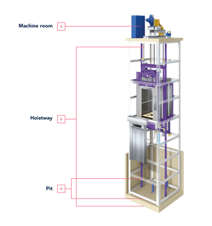
One of the significant advantages of gearless machines is the potential elimination of a machine room, saving valuable space. These are often referred to as MRLs (Machine Room Less).If a lift does require a machine room, it's typically located directly above the lift hoistway. This restricted area houses the sheave, motor, controller, governor, brake, and reduction gear, and is accessible only to expert engineers.
The Hoistway and The Pit
The hoistway is the area in which the lift moves up and down. If a machine room is required, it's generally situated above the hoistway. The area below the hoistway to the sill of the lowest landing is known as the 'pit'.
The pit houses counterweight and lift car buffers, which prevent the counterweight and lift car from descending past their standard limit. For slower lifts, the buffers can be made from Polyurethane, but for lifts moving at 1.6m/s and above, hydraulic buffers are necessary to absorb the kinetic energy of the lift. The pit also contains a ladder for engineer access and often houses the governor rope and governor tension device.
Essential Lift Components
Governor: The Safety Device
Most lifts feature an Overspeed Governor, a crucial safety device that activates if the lift's speed exceeds a set limit, ensuring passenger safety. The governor is connected to a rope linked to the lift car/cab. During normal operation, the governor rope moves in tandem with the lift car. If the lift's speed surpasses a pre-set limit, a locking mechanism within the governor engages 'gear teeth' within the wheel to halt its spinning. This action stops the governor rope, activating the safety gear onto the guide rails. A governor is a mandatory component of a traction lift.
The Lift Doors: Double Protection
A lift essentially has two sets of doors: one set for each floor and another set on the lift car. For safety reasons, the lift cannot move unless all doors are securely closed. The lift car door is operated by a mechanism located on top of the car door. However, the landing doors lack a similar mechanism and are opened and closed by the car door. The car door cam serves as the interface between the car door and the landing door, unlocking and opening the landing door when the car reaches the correct floor.
The Control System: The Brain of the Lift
The control system, comprising the controller and the drive, is the brain of the lift. Its primary role is to transport passengers to their desired floor, ensure a smooth ride, and regulate the lift's speed. The controller and drive can be packaged in various forms and are typically located on the landing near the top entrance, in the hoistway, or within the machine room.
The Cab or Car: The Passenger's Space
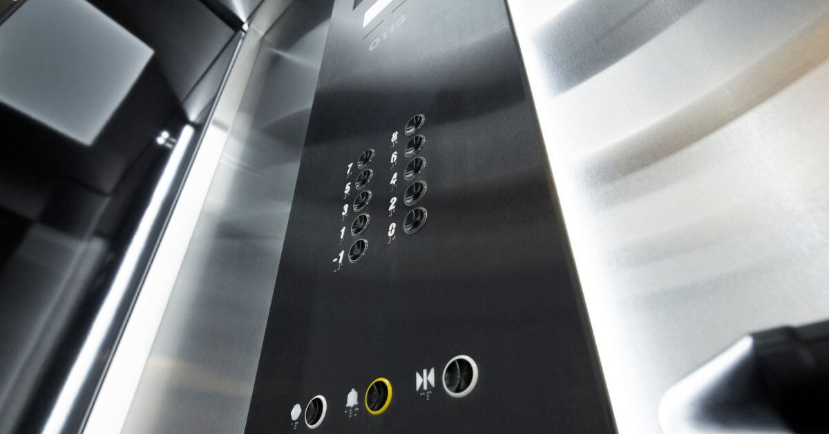
The car/cab is the part of the lift that passengers interact with most. It houses a control panel with buttons for passengers to select their destination. The car is guided by two guide rails, which are fixed with brackets to the hoistway. Over the years, lift cars have evolved to become more sophisticated and aesthetically pleasing. Modern lift cars can even feature screens that entertain and inform passengers during their journey.
By understanding the basic workings of lifts, we can appreciate the engineering marvels that they are. So, the next time you step into a lift, remember the intricate mechanisms working behind the scenes to ensure your safe and smooth journey.