Technological Options for the Production of SULFURIC ACID:
1. Contact Process2. Chamber Process
A Brief Summary of the Contact Process:
The sulfur dioxide is converted into sulfur trioxide by the reversible reaction taking place at the heart of the catalytic converter.
2SO2(g) + O2(g) → 2SO3(g)
The sulfur trioxide is first brought in to contact with a spray of lean sulfuric acid in the absorption tower wherein OLEUM is formed which on the addition of water finally gives rise to concentrated sulfuric acid.
H2SO4 (l) + SO3 (g)→H2S2O7 (l)
H2S2O7 (l) + H2O (l) → H2SO4 (l)
STEPS INVOLVED IN CONTACT PROCESS:
- The clean dry gases are drawn by a blower and passed through two heat exchangers so as to attain a temperature of about 420 ºC before entering the first mass of the converter.
- The catalyst is loaded in four converter beds of 9600, 11000, 13200, 22000 litres in volume respectively.
- Intermediate heat-exchangers are utilized for removing excess temperature of outlet gases.
- The gases from fourth bed outlet enter absorption tower through heat-exchanger. The SO3 gases are absorbed in the circulating absorption tower which is cooled there to 70 – 80-degree centigrade.
DESCRIPTION OF PROCESS:
Whatever SO2 produced in the roaster plant can discharge to the outside atmosphere but it causes a lot of pollution in the atmosphere. So to avoid pollution caused by this pollutant and to produce sulphuric acid, the acid plant is designed with effective scrubbers.
Here the acid plant is a conventional single contact acid plant having a four pass converter utilizing vanadium pentoxide as a catalyst.
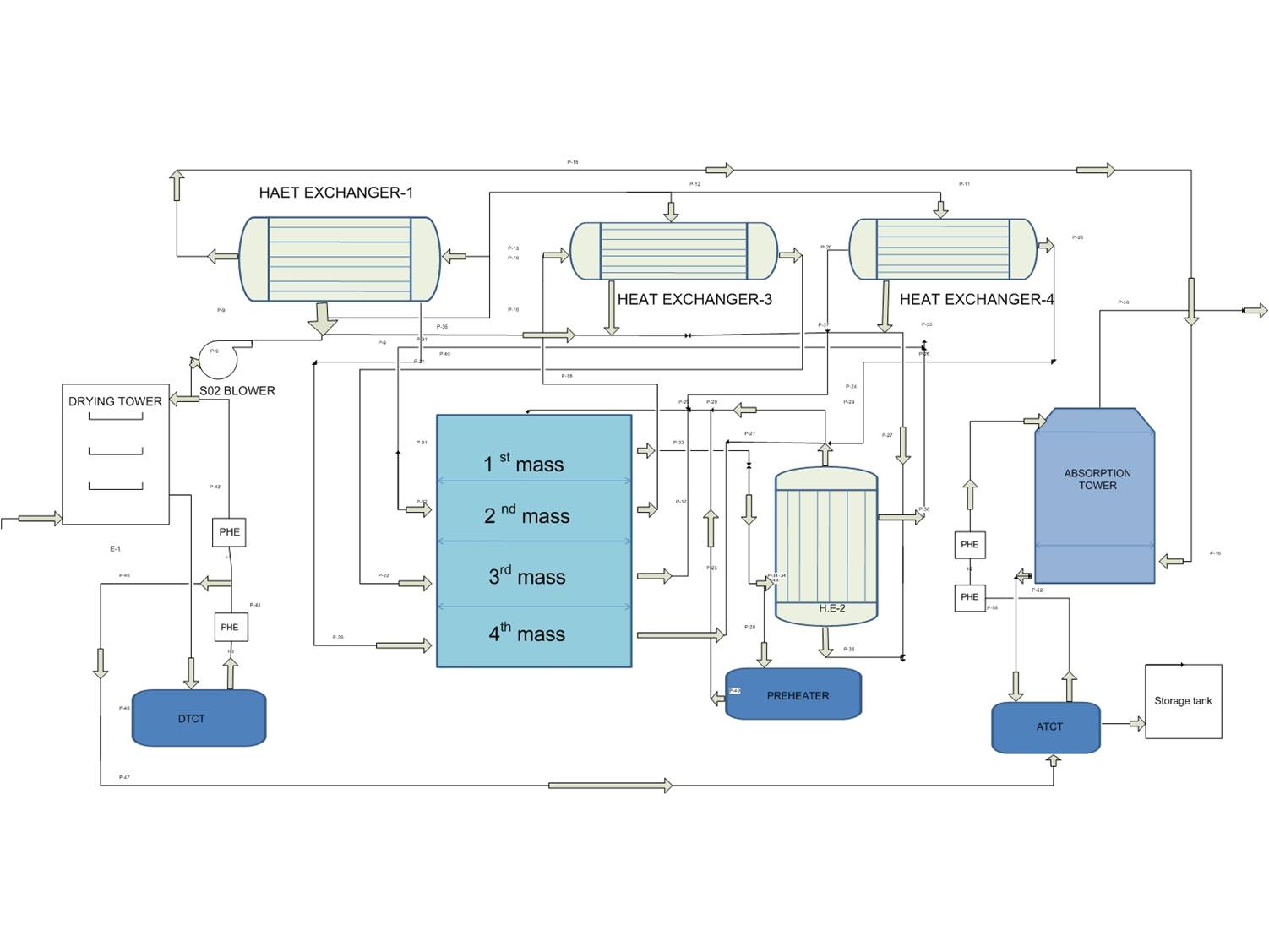 |
| Block diagram of sulfuric acid production by the contact process |
Description of gas flow :
The gas flow from Drying tower to Absorption tower is as follows:
2. Maximum part of the gases from SO2 blower enters into shell side of heat exchanger 1, and the remaining part is allowed to pass through tube side of heat exchangers 3 & 4, the tube outlets of 3&4 are allowed to pass through gas mix, to the outlet of gas mix shell outlet of heat exchanger joins, the mixture of gases from 3,4, and 1 enter into tube side of heat exchanger 2,
3. The gases from 2 tube outlet enter into converter 1st mass, the Gases from the 1st mass outlet are sent to 2 shell side of the heat exchanger, the shell outlet of 2 is sent to converter second mass.
4. The outlet of second mass is sent to the shell side of the heat exchanger, the shell outlet of the heat exchanger is sent to converter 3rd mass, the 3rd mass outlet is sent to shell side of the heat exchanger.
5. The outlet of the heat exchanger is sent to converter 4th mass, the 4th mass outlet is sent to the tube side of the heat exchanger, the tube outlet of the heat exchanger is allowed to pass through absorption tower. gas flows from D.T to A.T.
The gases from roaster with 5-7 % SO2 with O2 in the ratio 1:1.5 passes successively through the four beds of the converter containing volumes and of moisture are dried in the drying tower.
Drying tower description:
The drying tower is made up of a steel shell with an acid proof brick lining and it is packed with rasching rings for proper contact between SO2 and 96.5 % con sulphuric acid. The moisture carried out by gases is removed by circulating 96.5 % sulphuric acid at a rate of 220 m3/hr through vertical submerged pumps in the countercurrent direction to the flow of gases. The acid which is circulating in drying tower is cooled by using plate heat exchangers.
The important components in the acid plant are:
1. Drying Tower (D.T)
2. SO2 Blower
3. Converter
4. Heat exchangers 1, 2,3, 4 (With alonised tubes)
5. Absorption Tower (A.T)
6. Product acid storage tanks 1,2,3 & 4 (each of 1500 MT capacity)
The dry and preheated SO2 bearing gases containing 5-7 % by volume of SO2 with O2 in the ratio of 1: 1.5 passes successively through the four beds of the converter. Depending on the conversion percent of SO2 to SO3 temperatures of exit gases of each pass varies, to maintain heat balance in the process converter is provided with interstage cooling.
Inlet and exit gas temperatures of each pass are given below :
Pass no.
|
Inlet temperature
|
Outlet temperature
|
1st pass
|
420
|
580
|
2nd pass
|
430
|
490
|
3rd pass
|
430
|
475
|
4th pass
|
420
|
425
|
After conversion in the first bed, the gas mixture containing SO2 and SO3 are partially cooled to the temperature suitable for subsequent conversion in the next pass.
So in this way, interstage cooling after each pass is carried out by heat exchangers. The converter exit gases containing SO3 is cooled by passing through heat exchanger effluent heat exchanger before it enters into absorption tower.
So in this way, interstage cooling after each pass is carried out by heat exchangers. The converter exit gases containing SO3 is cooled by passing through heat exchanger effluent heat exchanger before it enters into absorption tower.
The cooled SO3 gas after entering the absorption tower meets a countercurrent downpour of 98.0 % sulfuric acid at 650 ºC, which is uniformly distributed through cast iron distributors across the packed bed of rasching rings. An almost entire quantity of SO3 gas dissolves in the acid and increases the concentration of tower return acid. This rise in acid concentration will be regulated by adding calculated quantity water to AT circulation tank and thus maintain the acid concentration at 98.0 %. So the increased volume gives the production volume of sulphuric acid. The product sulphuric acid is diverted to storage tanks through product PHE (plate heat exchangers). The entrained acid along with vent gases is arrested by honeycomb packing which is placed at the acid distributors and is returned to the packed bed and acid mist is escaping dry bed packing is retained by means of demister pads.
The flue gases containing unconverted SO2, SO3, N2 and O2 are first drawn by blower present in the TGT (Tail gas treatment plant ) to reduce SO2 content then discharged out.
Catalyst used:
1. Vanadium Pentoxide is used as the catalyst in the converter.
2. The Catalyst is in the form of porous pellets.
3. The composition of the catalyst pellet is
Catalyst used:
1. Vanadium Pentoxide is used as the catalyst in the converter.
2. The Catalyst is in the form of porous pellets.
3. The composition of the catalyst pellet is
V2O5 - 6-7%
K2O- 5-8%
SiO2 – 50 – 60%
K2O- 5-8%
SiO2 – 50 – 60%
4. The K2O act as promoters and SiO2 acts as the physical support to the catalyst